Demco 800 BUSHEL User manual

Page1
OPERATORS MANUAL
READ complete manual CAREFULLY
BEFORE attempting operation.
800/950 BUSHEL
DEMCO ï Dethmers Mfg. Co. ï 4010 320th St. ï P.O. Box 189 ï Boyden, IA 51234
PH: (712) 725-2311 ï Toll Free: 1-800-543-3626 ï FAX: 1-800-845-6420
www.demco-products.com
ASSEMBLY
CALIBRATION
OPERATION
REPLACEMENT PARTS
01/04
AG20022 Rev 1
DOING OUR BEST TO PROVIDEYOU THE BEST
GRAIN CART

Page2
GENERAL INFORMATION
1. Unless otherwise specified, high-strength (grade5) (3
radial-line head markings) hex head bolts are used
throughout assembly of this piece of equipment.
2. Whenever terms "LEFT" and "RIGHT" are used in this
manual it means from a position behind wagon box and
facing forward.
WARNING: TO AVOID PERSONAL INJURY OR DEATH, OBSERVE FOLLOWING
INSTRUCTIONS:
Ensure that anybody present is clear before applying power to any machinery used in
conjunction with grain cart or when moving grain cart.
Never allow anyone in, near, or on grain cart during transporting or unloading of grain.
Movinggrainisdangerousandcancauseentrapment,resultinginsevereinjuryordeath
by suffocation.
Do not exceed 20 miles per hour when towing grain cart.
Table of Contents
General information and Bolt Torque ................................... 2
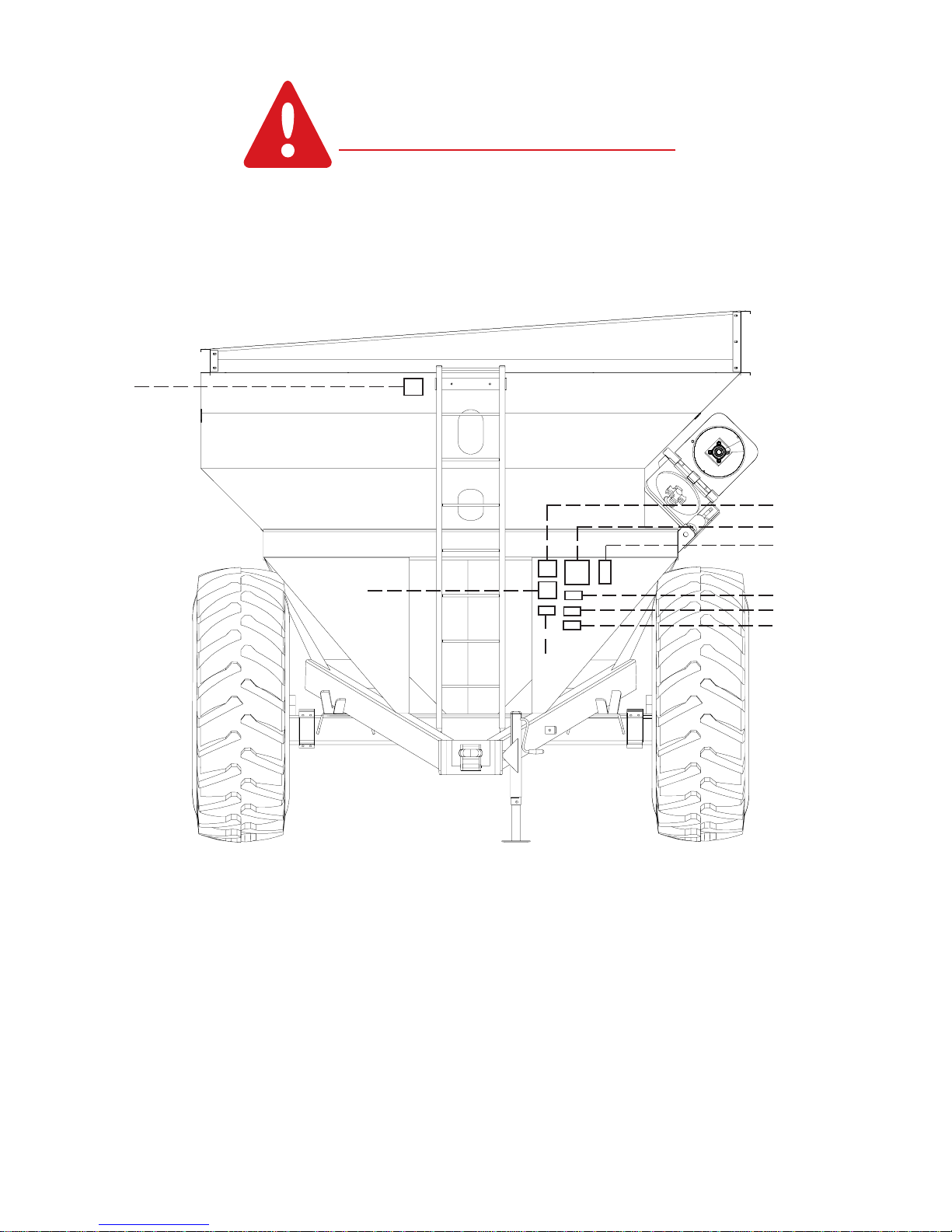
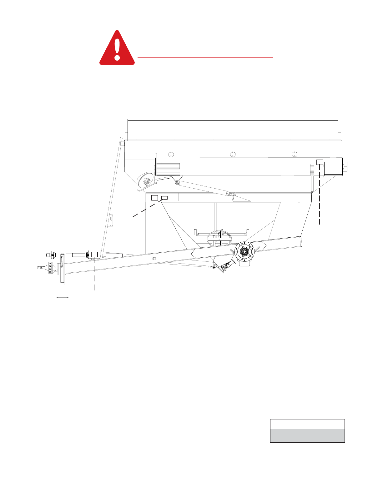
Safety Sign Locations ....................................................... 3-4
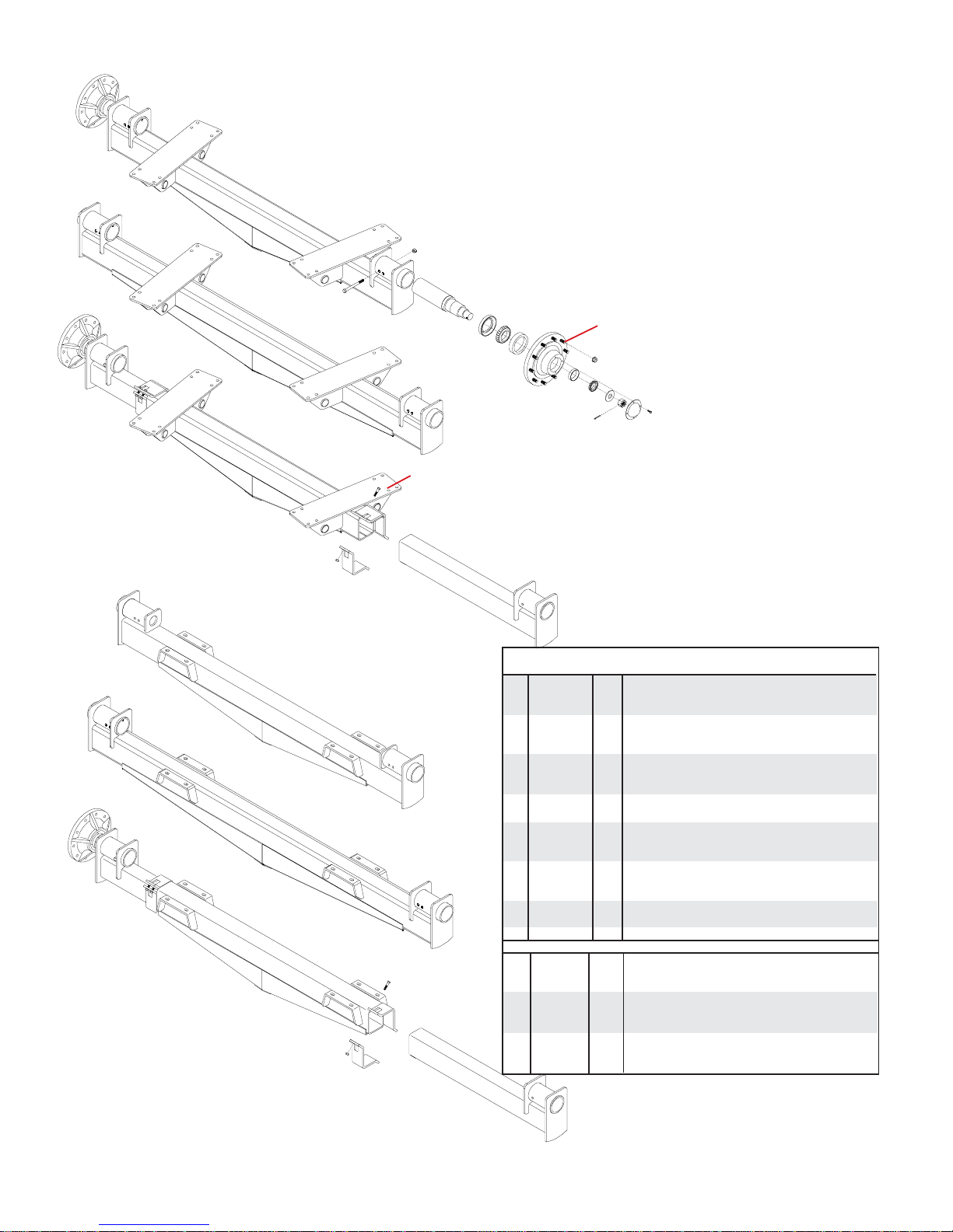
Axle Assembly and Parts Breakdown................................. 5
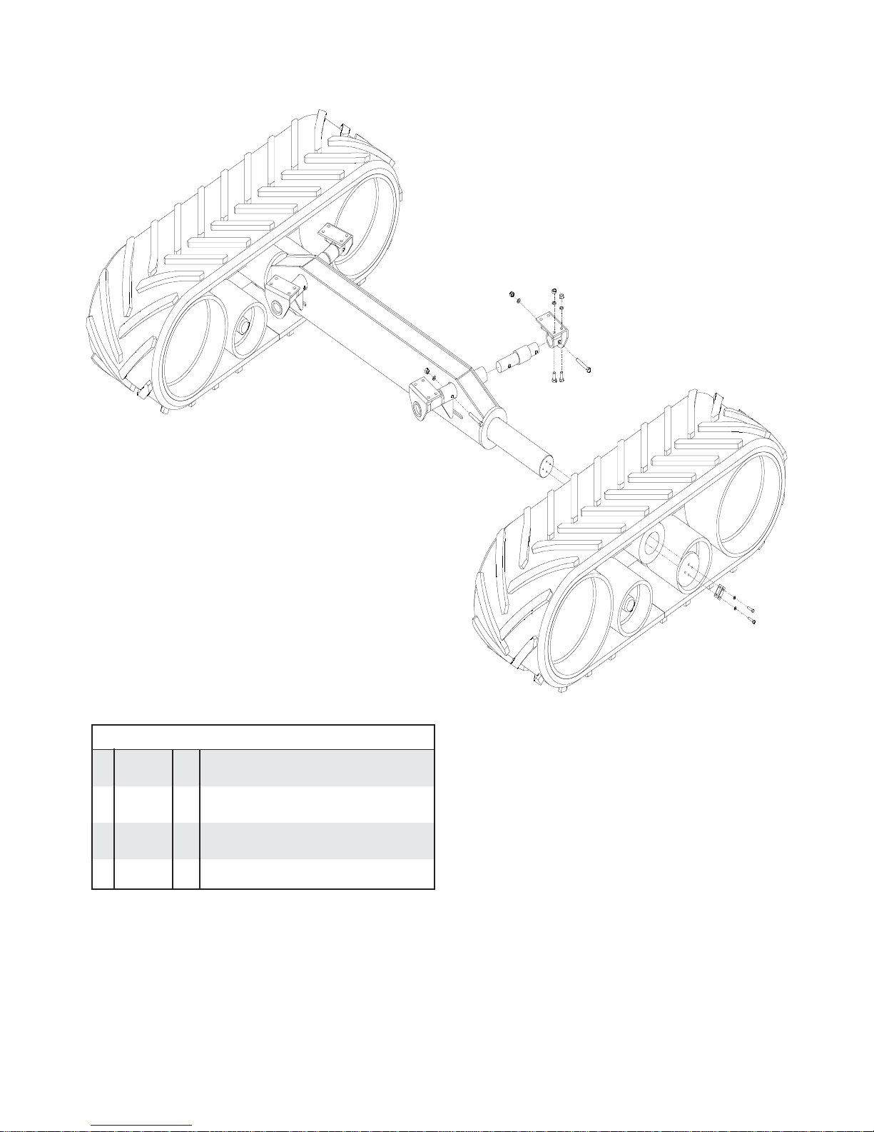
Track Axle Assembly and Parts Breakdown....................... 6
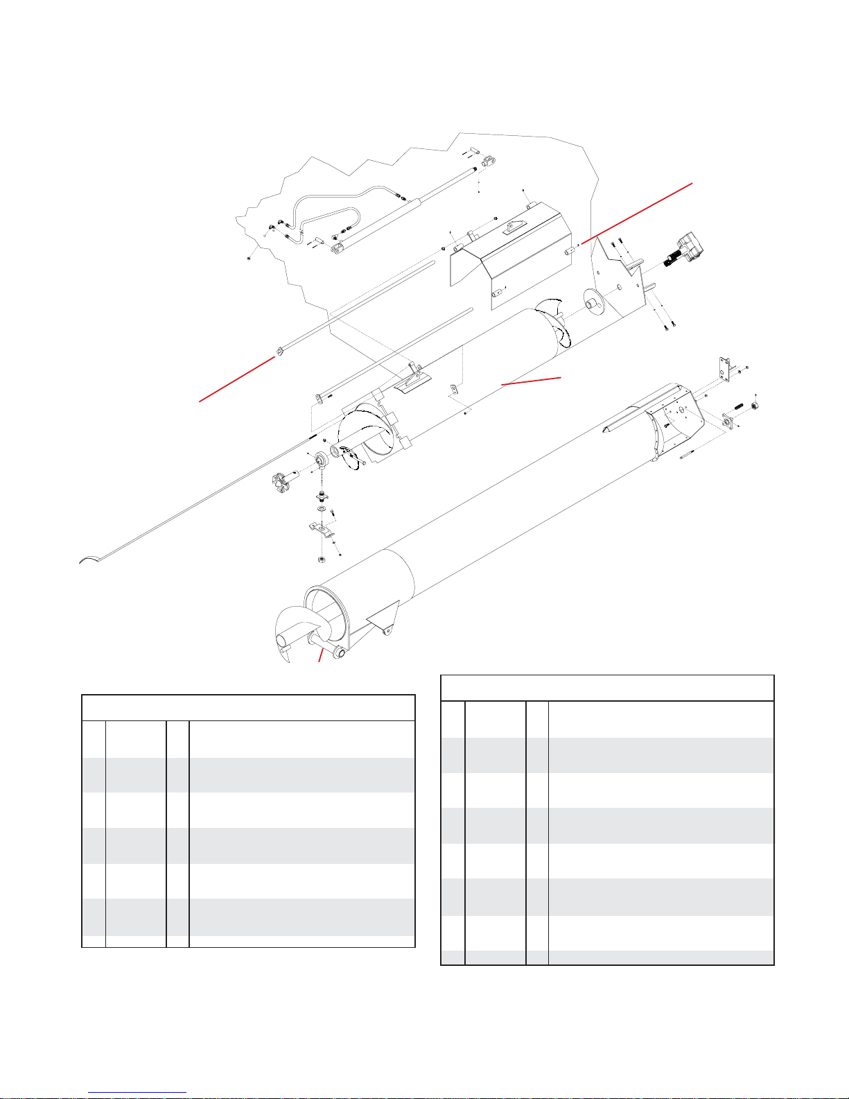
Auger Assembly and Parts Breakdown............................... 7
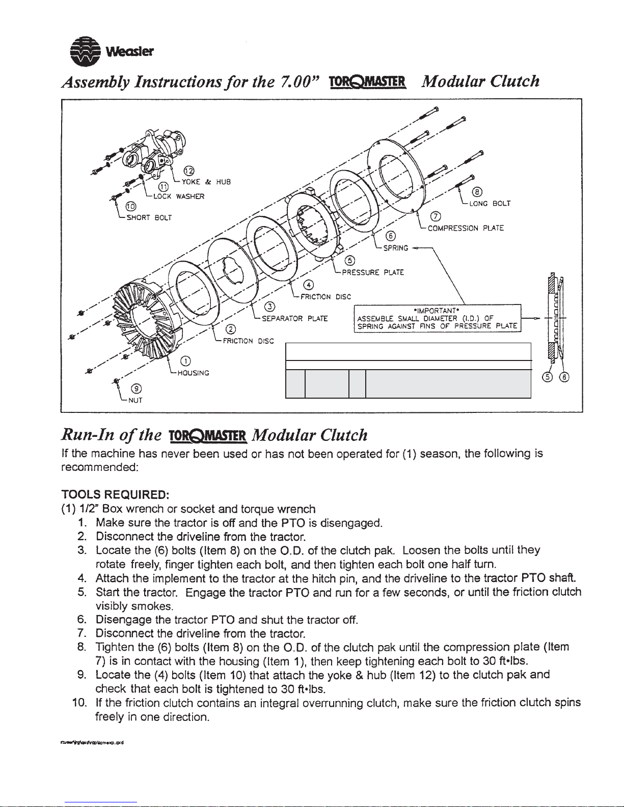
Weasler Modular Clutch Assembly and Parts Breakdown . 8
PTO Drive Assembly and Parts Breakdown ....................... 9
Hydraulic Drive Assembly and Parts Breakdown ............... 9
Grain Cart Assembly and Parts Breakdown ................... 10-11
950 Bushel Extensions Assembly and Parts Breakdown .. 12
Hydraulics Assembly and Parts Breakdown...................... 13
Lighting Assembly and Parts Breakdown .......................... 14
Scale Option and Parts Breakdown ................................... 15
Scale Assembly and Parts Breakdown for Tracks ............. 16
Dial Indicator Assembly and Parts Breakdown.................. 17
Door Lift Assembly and Parts Breakdown ......................... 18
Window Assembly and Parts Breakdown .......................... 18
Maintenance, Grease and Lube ......................................... 19
Grain Cart Checklist .......................................................... 20
Thank you for purchasing a Demco Grain Cart. We feel you have made a wise choice and hope you are completely
satisfied with your new piece of equipment. Proper care and use will result in many years of service.
INTRODUCTION
3. When placinga parts order,referto thismanualfor proper
part numbers and place order by PART NO. and DE-
SCRIPTION.
4. Read assembly instructions carefully. Study
assemblyproceduresandallillustrationsbeforeyoubegin
assembly. Note which parts are used in each step. This
unit must be assembled in proper sequence or complica-
tions will result.
Torque figures indicated are valid for non-greased or non-
oiled threads and heads unless otherwise specified. There-
fore, do not grease or oil bolts or capscrews unless other-
wise specified in this manual. When using locking
elements, increase torque values
by 5%.
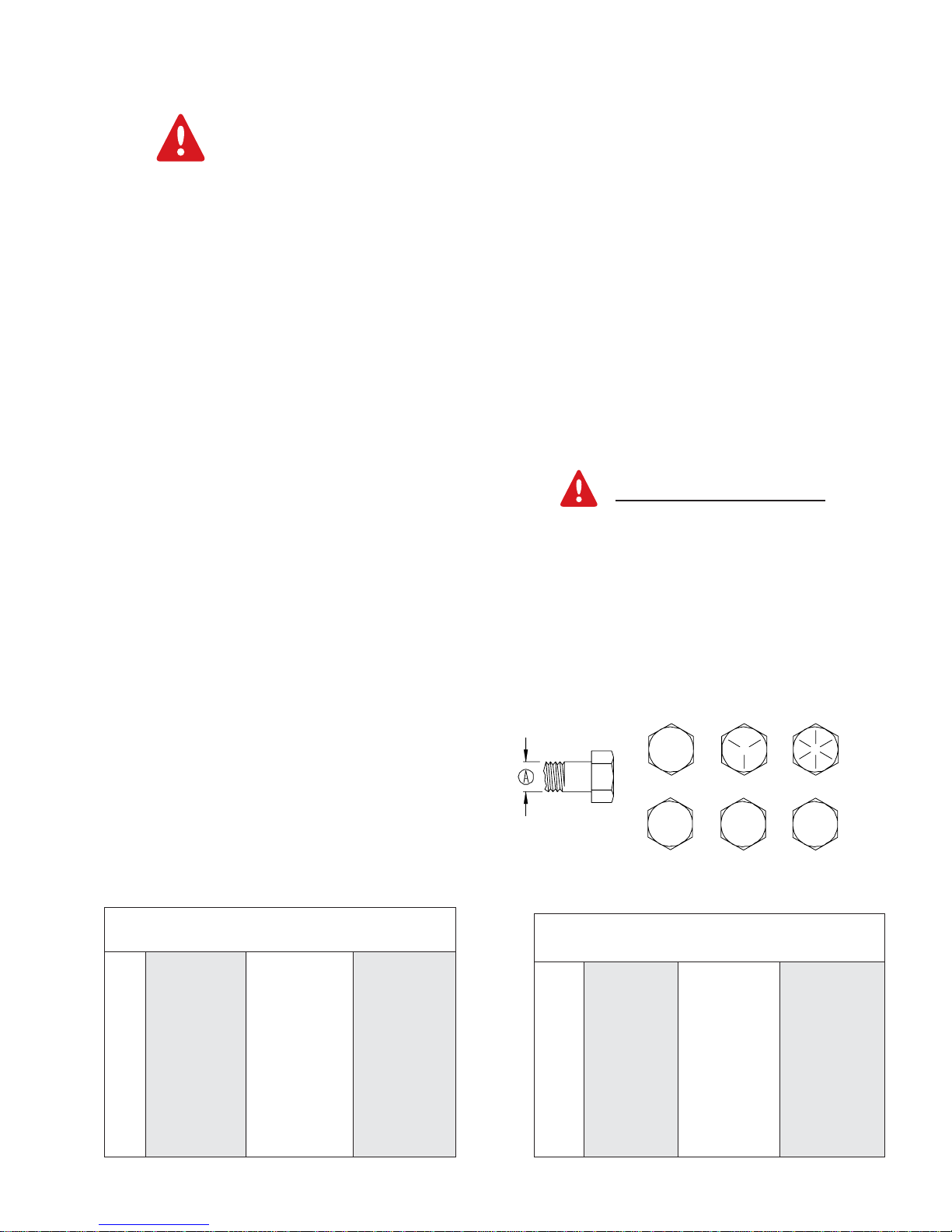
* GRADE or CLASS value for bolts and capscrews are
identified by their head markings.
Torque Specifications
Bolt Torque for Metric bolts *
CLASS 8.8 CLASS 9.8 CLASS 10.9
ìAî lb-ft (N.m) lb-ft (N.m) lb-ft (N.m)
6 9 (13) 10 (14) 13 (17)
7 15 (21) 18 (24) 21 (29)
8 23 (31) 25 (34) 31 (42)
10 45 (61) 50 (68) 61 (83)
12 78 (106) 88 (118) 106 (144)
14 125 (169) 140 (189) 170 (230)
16 194 (263) 216 (293) 263 (357)
18 268 (363) -- -- 364 (493)
20 378 (513) -- -- 515 (689)
22 516 (699) -- -- 702 (952)
24 654 (886) -- -- 890 (1206)
BOLT TORQUE DATA FOR STANDARD
NUTS, BOLTS, AND CAPSCREWS.
Tighten all bolts to torques specified in chart unless other-
wise noted. Check tightness of bolts periodically, using bolt
chart as guide. Replace hardware with same grade bolt.
NOTE: Unless otherwise specified, high-strength Grade 5
hex bolts are used throughout assembly of equipment. Bolt Torque for Standard bolts *
GRADE 2 GRADE 5GRADE 8
Alb-ft (N.m) lb-ft (N.m) lb-ft (N.m)
1/46 (8) 9 (12) 12 (16)
5/1610 (13) 18 (25) 25 (35)
3/820 (27) 30 (40) 45 (60)
7/1630 (40) 50 (70) 80 (110)
1/245 (60) 75 (100) 115 (155)
9/1670 (95) 115 (155) 165 (220)
5/895 (130) 150 (200) 225 (300)
3/4165 (225) 290 (390) 400 (540)
7/8170 (230) 420 (570) 650 (880)
1225 (300) 630 (850) 970 -(1310)
GRADE-2 GRADE-5 GRADE-8
8.8 10.9
9.8
CLASS 8.8 CLASS 9.8 CLASS 10.9

Page3
SAFETY SIGN LOCATIONS
Typesofsafetysignandlocationsonequipmentareshowninillustrationbelow. Goodsafety
requires that you familiarize yourself with various safety signs, type of warning, and area or
particular function related to that area, that requires your SAFETY AWARENESS.
#1 DANGER - Do not enter grain tank when auger is running!
#2 DANGER - Keep off ladder while machine is being moved or in operation!
#3 WARNING - Read and understand the operatorís manual!
#4 WARNING - Keep hands and clothing away from moving parts!
#5 DANGER - Never play in or on grain! Farm safety just 4 kids!
#6 DANGER - Electrocution can occur without direct contact with power lines !
#7 WARNING - Read manual, keep all shields in place, cleaning or clearing
a clogged machine, keep hands, feet, and clothing away,
do not stand or climb on machine, no riders!
#8 WARNING - Avoid bodily injuries from hydraulic oil under pressure.
#1
#4
#7
#6
#5
#3
#2
#8
#14

Page4
# 9 DANGER - This decal is on pto shaft, Guard is missing do not operate!
#10 DANGER - Pinch- point keep hands and clothing away from moving parts!
#11 WARNING - Keep all persons and objects clear while any part of
this machine is in motion!
#12 DANGER - Electrocution can occur without direct contact with power lines!
#13 DANGER - Rotating driveline!
#14 WARNING - Do not exceed 20 MPH when towing Grain Cart
#15 Decal Kit- Decals #1 - #14 are available as a kit.
#9
#11
#10
Decal order number
AG21064
#12
#13
SAFETY SIGN LOCATIONS
Typesofsafetysignandlocationsonequipmentareshowninillustrationbelow. Goodsafety
requires that you familiarize yourself with various safety signs, type of warning, and area or
particular function related to that area, that requires your SAFETY AWARENESS.

Page5
AXLE ASSEMBLY
1
2
4
6
13
17
19 15
12
3
18
21
20
16
8
Pleaseorder replacementpartsby PARTNO. andDESCRIPTION.
Painted Parts are available in Red or Green. Add -10 behind
the part number for red, -20 behind the part number for green,
and -30 behind the part number for black.
9
10
22
* NOTE: The 3/4î stud must be driven out and replaced with the
1î stud when duals are mounted on the hub of the grain cart
14
NOTE: The long fixed axle (item #2 & #2a) must be used with
dual rims and tires.
23
*Duals Only
7
11
REF. PART
NO. NO. QTY. DESCRIPTION
1. 11174-30 1 Fixed 120î Axle (950)
1a. 09668-30 1 Fixed 120î Axle (800)
2. 11428-30 1 Fixed Axle for Duals only (950)
2a. 11580-30 1 Fixed Axle for Duals only (800)
3. 11175-30 1 Adjustable Axle (950)
3a. 09684-30 1 Adjustable Axle (800)
4. 09206-30 2 Axle Insert
6. 09204 2 Axle Spindle
7. 11712-30 2 Axle Clamps (950)
7a. 09214-30 2 Axle Clamps (800)
8. 04836 2 5/8î-11 UNC x 7î Hex Head Bolt
9. 02587 2 5/8-11 UNC Nylon Insert Locknut
10. 11613 8 1/2î-13 UNC x 2-1/2î Hex Head Bolt (Gr. 8)
11. 02178 8 1/2î-13 Nylon Insert Locknut
12. 09445 1 2î-12 UNF Castle Nut
13. 09444 1 2-1/16î ID x 4î OD x 1/4î Washer
14. 09446 1 3/8î x 3î Cotter Pin
15. 07861 - Replacement 3/4îNF x 2-3/4î Stud Bolt
*-10827 - Replacement 1îNF x 4î Stud (Duals ONLY)
-11295 - Replacement 3/4îNF x 2-3/4î Stud (35.5 x 32 only)
5540 2 Hub Assembly(Includes items16-22)
16. 09448 1 Outer Bearing Race (HM212011)
17. 09450 1 Outer Bearing (HM 212049)
18. 09449 1 Inner Bearing (HM 218248)
19. 09452 1 Inner Grease Seal (CR43771)
20. 09447 1 Inner Bearing Race (HM218210)
21. 09451 1 Dust Cap
22. 04305 4 5/16-18 UNC x 1/2î Hex Head Bolt (Gr.5)
23. 07435 20 3/4î-16 UNF Lug Nut
- ---- 20 1î-16UNF Lug Nut w/ washer (Incl.with10827 stud bolt)
4
1a
2a
3a
*Duals Only
7a
950Axles
800Axles

Page6
TRACKAXLEASSEMBLY
1
REF. PART
NO. NO. QTY. DESCRIPTION
Pleaseorder replacementparts by PARTNO. andDESCRIPTION. * NOTE: Refer to OmnitracÆ owner/parts manual for proper
maintenence and operation of the tracks on this grain cart.
1. 10938-30 1 Track Axle
2. 10939-30 4 Axle Mounting Plates
3. 10940 4 WeighBar
4. 10945-30 2 Axle End Cap
5. 10946-95 4 Locking Tab (plated)
6. 11094 1 Tracks(1 pair)
7. 00254 24 1/2îSpringLockwasher
8. 01253 8 1/2îNC X 2.00î Hex Head Bolt (Gr. 5)
9. 11097 16 3/4îNC X 2.00î Hex Head Bolt (Gr. 8)
10. 11098 24 3/4îNCHex Nut (Gr.8)
11. 11099 8 3/4îNC X 5.00î Hex Head Bolt (Gr. 8)
2
2
2
2
5
3
4
7
6
6
7
7
7
7
7
8
9
10
10
10
11
11

Page7
AUGER ASSEMBLY
2
5
35 25
6
8
24
3
4
20
13
14 12
15
17
18
19
16
21
22
23
27 25
26
28
29
30
1
31
9
34
32
25
33
REF. PART
NO. NO. QTY. DESCRIPTION
14
29
30
31
35
1. 11100-? 1 Outer Auger Tube
2. 11134-30 1 OuterAugerFlighting
3. 10634 1 Flange Bearing
4. 09168 4 Upper Auger Spring
5. 01922 1 1-1/2î-12 UNF Hex Nut w/ Set Screw Hole
6. 01923 1 1/4î Socket Hd. Cup Point Set Screw x 1/4î
7. 00789 1 3/8î-16 UNC x 3/8î Socket Head Set Screw
8. 01338 4 1/2îNC x 4-1/2î Hex Head Bolt (Gr. 5)
9. 10607 1 GearBox
10. 01254 12 1/2î-13UNC x1-1/2î HexHead Bolt(Gr.5)
11. 00084 4 1/2î Lockwasher
12. 10623-30 1 Lower Drive
13. 10613-30 1 LowerAugerFlighting
14. 09203 2 SlideRod
15. 00523 2 3/8î-16UNC x1-1/4î HexHead Bolt(Gr.5)
16. 02592 2 3/8î-16Nylon InsertLocknut
17. 04205 1 5/8î-11UNC x5î Hex HeadNut (Gr.8)
18. 02587 1 5/8î-11UNCNylonInsertLocknut
19. 09185 1 2îHangerBearing
REF. PART
NO. NO. QTY. DESCRIPTION
36
10
7
Please order replacement parts by PART NO. and DESCRIPTION.
Painted Parts are available in Red or Green. Add -10 behind the
part number for red and -20 behind the part number for green.
11
Lower auger
shown here
for clarity
NOTE: Be sure to check
and lubricate the inner gate
when doing the mainte-
nance on page 19 or every
20hours.
10
2425
37
NOTE: Be sure to check
and lubricate the slide gate
guide rods when doing the
maintenance on page 19.
20. 00482 2 1/2î- 13UNC x 1-3/4î Hex Head Bolt (Gr. 5)
21. 09195-30 1 HangerBearingMount
22. 10624-30 1 Hanger Bearing Plate
23. 07412 1 1-1/4î-12UNFJamNut
24. 00085 6 1/2îFlatwasher
25. 02178 11 1/2î-13UNCNylonInsertLocknut
26. 10618-30 1 MaleAugerConnection
27. 10604-30 1 GaugeRod
28. 10602-30 1 InnerDoor
29. 03738-95 2 1î Dia. x 3î Cylinder Pin
30. 00116 4 5/32î x 1-1/2î Cotter Pin
31. 05195 2 Straight Hyd. Ftg. 3/8î MPT x 3/8î JIC
32. 09930-30 1 2-1/2îCylinder x 30î Stroke
-5584 - HydraulicCylinderSealRepairKit (notshown)
33. 00083 1 1/2î-13UNCHexHeadNut
34. 05191 2 36îHydraulicHose
35. 09172 2 3/8î JIC Bulkhead Elbow Ftg. W/Nut
36. 09741-30 1 AdjustableCylinderClevis End
37. 11103-30 1 Auger Rest Bracket
38. 04642 5 Grease Zerk
39. 05089 1 1 1/4î Machine Washer NR
40. 05215 1 3/8î MPT x 3/8î FPT Hyd. Elbow Fitting
38
38
38
38
10
11
39
40
38

Page8
09512 -11658 - Complete 7.00î Clutch Assembly
1. 09512 2 Replacement Friction Disc
2. 10873 1 Replacement Separator Plate
3. 10874 1 Replacement Spring
REF. PART
NO. NO. QTY. DESCRIPTION
09512
10873
10874

Page9
REF. PART
NO. NO. QTY. DESCRIPTION
Please order replacement parts by PART NO. and DESCRIPTION.
HYDRAULIC DRIVE ASSEMBLY
Operation
ï Makesurethehydraulicmotorisconnectedto
the tractorís priority port.
ï Thehydraulicreturnlineshouldfree-dump
directly into the reservoir.
PTO DRIVE ASSEMBLY
1. 11036 1 PTO Inner Guard
2. 11037 1 PTO Outer Guard
3. 11038 2 Cross and Bearing for 800 & 950 Grain Cart
REF. PART
NO. NO. QTY. DESCRIPTION
2
1
3
1. 05197 2 Quick Coupler (1/2î FPT with male tip)
2. 11219 2 HydraulicHose
3. 02178 8 1/2î-13UNCNylonInsertLocknut
4. 11225 2 HydraulicO-RingFitting (Pumpto Hose)
5. 11217 1 HydraulicMotor
6. 05256 2 3/8îNC X .50î Socket Head Set Screw
7. 00967 4 1/2î-13UNC x 1.25î Bolt Gr.5)
8. 01253 4 1/2î-13UNC x 2.00îBolt (Gr.5)
9. 11221-30 1 Hyd.Motor Mounting Plate
10. 11218 1 Universal Joint with Clutch
11. 05198 2 RubberQuickCouplerCover
12. 11220 1 Drive Shaft For Hyd. Drive
13. 11216 2 Adapter Union (.50 MPT X .75 FPT)
2
1
3
7
8
5
4
11
10
9
12
13
6
NOTE: IN ORDER TO MOUNT PLATE #9;
FOUR .56 DIA. HOLES WILL NEED TO BE
DRILLED THROUGH THE BEARING PLATEAS
SHOWN

Page10
LOADING AND UNLOADING GRAIN
ï With the gate indicator in the closed position, fill the
box with grain.
ï With the PTO disengaged, extend auger.
ï Start PTO at a slow rate of speed until the upper
and lower drives are engaged.
ï Increase PTO speed and open the inner gate
halfway. When grain begins to flow, open gate to
fullposition.
ï Once grain stops flowing, return gate to closed
position.
ï Never exceed 1000 RPM on the system.
ï Never fill grain cart unless inner gate is closed.
WARNING: BE CERTAIN ALL POWER
IS OFF WHEN CONNECTING PTO OR
HYDRAULIC LINES TO TRACTOR
ï Connect Grain Cart to tractor using a good quaility
hitch pin. Attach a safety chain.
ï Attach power take-off shaft to tractor. Check tractor
drawbar and adjust to allow clearance.
ï Raise jack stand and place to rear storage
position.
ï Make sure no debris is in the grain cart.
ï Attach hydraulic lines to tractor.
ï Connect lighting hook-up to tractor.
1
48
53
46
4
GRAIN CART ASSEMBLY
For Extension Breakdown See Page 12
ForWindow
Installation See
Page18
5
8
8
17
39
3
6
53
63
7
46
47
2
1
58
14
52
9
74
39
10
19
15
47
10
55
10 69
51
11 12
13
45
53 53
55
17
16
18
23
16
55
43
17
54
55
54 56
54 58
55
54
22
20
67
25
21
24
44
26
57
31
27
32
33
28
50
49
45
46
47
64
60
61,62
47
68
57
64
59
76
66
47
For Dial Indicator
Installation See
Page 17
69
12
44
75 75
74

Page11
REF. PART
NO. NO. QTY. DESCRIPTION
GRAIN CART ASSEMBLYAND OPERATION
For Auger Breakdown See Page 7
For Axle Breakdown See Pages 5-6
For Door
Lift Break-
down See
Page 18
ï Disengage PTO and allow it to come to a complete
stop. Auger is now ready to fold to stored position.
DO NOT PULL THE GRAIN CART UNLESS THE
AUGER IS IN THE STORED POSITION.
ï Never fold or extend auger unless PTO is com
pletely stopped.
ï Never engage auger when system is moving at a
high rate of speed.
ï Never do maintenance work or service cart while the
tractor is running.
31
34
35
35
30
44
29
40
37
41
42
36
38
57
47
Please order replacement parts by PART
NO.andDESCRIPTION.
Painted Parts are available in Red or
Green. Add -10 behind the part number
for red and -20 behind the part number
for green.
For Hydraulics Breakdown
See Page 13
NOTE: Torque lugnuts to 500 ft/lbs and inflate
tires to specified amount on the tire. Check
Weekly.
57
1. 03159 2 Square Cap Plug
2. 10621-30 1 Ladder
3. 10609-30 1 PTO Shaft Guard Step
4. 10595-? 1 Undercarriage/Box for 950 Grain Cart
-11513-? 1 Undercarriage/Box for 800 Grain Cart
5. 07310 2 Rubber Grommet for Window
6. 07276 2 Window
7. 10612 1 Drive Shaft for 950 BU Grain Cart
8. 10622 2 5/16î x 5/16î x 2-3/4î Key
9. 09163-30 1 Category 4 Forged Hitch Base
10. 09164-30 1 1-1/4î Clevis InsertW/3/4î x 6î Gr.8 Bolt &Nut
11. 10813-30 1 Pintle Ring Mount
12. 11698 2 7/8î x 5 1/2î Hex Head Bolt Gr. 8
13. 10814 1 Hitch Pin
14. 09219-30 1 7000# Sidewind Jack with Mount
15. 10610-30 1 Front Safety Shield
16. 10611-30 2 Rear Safety Shield
17. 10633 3 35mm 4-Bolt Flange Bearing
18. 10617-30 1 Bearing Mount for Drive Shaft
19. 10615 1 Universal Joint
20. 10658-30 1 Pointer Assy.
21. 10659-30 1 Dial Indicator Plate
22. 10660-30 1 Pointer Mounting Plate
23. 10661-30 1 Pointer Brkt Assy.
24. 10673 2 Tension Spring for Pointer
25. 10080 1 Cable For Pointer
26. 10631-30 1 Folding Pin
27. 10637-30 1 Door Lift Channel
28. 10620-30 1 Lower Outside Door
29. 10629-30 1 Door Lift Wheel
30. 11525-30 1 Door Lift Mount
31. 03738-95 2 1î x 3î Cylinder pin
32. 09930-30 1 Hydraulic Cylinder
33. 09741-30 1 Adjustable Cylinder End
34. 09198-30 1 Folding Cylinder Mount
35. 07412 2 1-1/4îJam Nut
36. 11102 1 AugerDischargeRubberBoot
37. 10032 1 Left Ag Light
--. 10033 1 Right Ag Light
38. 09437 1 4îSealed BeamLight
39. 61681 7 1îAnti-Skid Tape
40. 9445208 2 Single Wheel (30.5L x 32 24 ply Tire)(Rim Incl.)
--. 10401-56 2 VA27 x 32 Rim
--. 9445204 2 Single Wheel (30.5L x 32 12 ply Tire)(Rim Incl.)
--. 09381-56 2 DW27A x 32 Rim
--. -- 2 Dual Wheel (520/85R-38 Tire)(Rims Incl.)
--. 10830 4 Dual Rim
41. 11565-30 2 Light Mount
42. 07435 20 3/4î-16 UNF Lug Nut
43. 10816-30 1 BearingMount
44. 00116 5 5/32î x 1-1/2î Cotter Pin
45. 00059 12 3/8î Flatwasher
46. 00523 6 3/8î x 1-1/4î Hex Bolt (Gr. 5)
47. 02592 27 3/8î Nylon Insert Locknut
48. 05047 16 3/4î-10UNC x 2-1/2îHex Head Bolt (Gr. 5)
49. 00492 16 3/4î Flatwasher
50. 02961 16 3/4î-10UNC Nylon Insert Locknut
51. 09454 2 1î-14 UNF x 6-1/2î Hex Head Bolt (Gr. 8)
52. 09455 2 1î -14 UNF Stover Locknut
53. 01254 18 1/2î x 1-1/2î Hex Head Bolt (Gr. 5)
54. 00085 20 1/2î Flatwasher
55. 02178 18 1/2î Nylon Insert Locknut
56. 05103 1 5/8î x 3-1/2î Hex Head Bolt (Gr. 5)
57. 00907 22 3/8î x 1î Hex Head Bolt (Gr. 5)
58. 05256 4 3/8î-16 UNC x 1/2î Socket Head Set Screw
59. 02772 4 1/4î Nylon Insert Locknut
60. 10277 1 ElectricalPlugHolder
61. 10241 1 OwnerísManualCannister
62. 10242 1 OwnerísManualCannisterBracket
63. 10666 1 1-3/4î PTO Shaft
64. 04055 4 1/4î x 1î Hex Head Bolt (Gr. 5)
65. 00639 8 1/2î x 1-1/2î Set Screw w/00640 Jam Nut
66. 00214 2 1/4îFlatwasher
67. 02587 1 5/8î Nylon Insert Locknut
68. 11568-30 2 Light Mount Reciever
69. 10678 2 7/8î Nylon Insert Locknut
70. 11104-30 2 Auger Chute Mounting Strip
71. 11105-30 2 Auger Chute Mounting Strip
72. 00639 4 1/2î x 1 1/2î Square Head Bolt
73. 00209 4 3/8î x 1î Square Head Bolt
74. 02990 14 5/16î x 1î Hex Head Bolt
75. 02802 14 5/16î Nylon Insert Locknut
76. 00004 22 5/16î Flatwasher
68
73
72
ForLighting
Parts
Breakdown
See Page
14
70
71

Page12
800 & 950 EXTENSION ASSEMBLY
REF. PART
NO. NO. QTY. DESCRIPTION
Please order replacement parts by PART NO. and DESCRIPTION.
1
3
2
4
96
8
5
6
8
8
11 12
11
10
979
7
1. 10625-30 1 Front Extension
2. 10630-30 1 Rear Extension
3. 10626-30 2 Left Extension
4. 10627-30 2 Right Extension
5. 10758 8 Side Hinge
6. 10759 4 Front & Rear Hinge
7. 00004 80 5/16î Flatwasher
8. 01263 92 5/16î x 3/4î Hex Hd. Bolt Gr. 5
9. 02802 98 5/16î Locknut
10. 10668-30 1 CrossAngle Brace
11. 00907 2 3/8î X 1î Hex Head Bolt (Gr. 5)
12. 02592 2 3/8î Nylon Insert Locknut
13. 02990 6 5/16î x 1î Hex Head Bolt Gr. 5
12
REF. PART
NO. NO. QTY. DESCRIPTION
14. 11510-30 1 Front Extension
15. 11511-30 1 Rear Extension
16. 11512-30 1 Left Extension
17. 00004 16 5/16î Flatwasher
18. 01263 20 5/16î x 3/4î Hex Hd. Bolt Gr. 5
19. 02802 20 5/16î Locknut
950 Extension Parts List
800 Extension Parts List
950 Grain Cart
800 Grain Cart
5
4
3
8
5
15
18
19
18
18
19
16
14
17
17
19
13
9

Page13
HYDRAULIC PARTS AND ASSEMBLY
REF. PART
NO. NO. QTY. DESCRIPTION
Item #8 is on opposite
side of fittings inside box
Please order replacement parts by PART NO. and DESCRIPTION.
Painted Parts are available in Red or Green. Add -10 behind the
part number for red and -20 behind the part number for green.
1. 05198 4 Rubber Coupler Cover
2. 05197 4 Hydraulic Quick Coupler
3. 05831 4 1/2î MPT x 3/8î FPT Reducer
4. 05840 2 1/4î x 84î Hydraulic Hose
5. 00914 3 3/8î-16 UNC x 1-1/2î Hex Head Bolt (Gr.5)
6. 02592 3 3/8î-16 UNC Nylon Insert Locknut
7. 09171 4 1/4î x 16í Hydraulic Hose
8. 05191 2 1/4î x 36î Hydraulic Hose (Not Shown)
9. 03743 2 .041î Hydraulic Swivel Restrictor
10. 05215 2 3/8î MPT x 3/8î FPT Elbow Fitting
REF. PART
NO. NO. QTY. DESCRIPTION
7
11. 09217-30 2 Hose Keeper (4 Hose)
12. 03547 1 5/16î-18 UNC X 2-1/4î Hex Head Bolt (Gr.5)
13. 07732 1 5/16î-18 UNC Nylon Insert Locknut
14. 07582 1 Pilot Operated Check Valve
15. 09172 2 3/8î JIC Bulkhead Elbow Fitting
16. 05195 2 Str. Hyd. Fitting, .375 MPT
17. 05243 4 Str. Hyd. Fitting W/O-Ring
18. 09930-30 1 2-1/2î Cylinder
19. 09218-95 3 Hose Keeper (2 Hose)
-5584 - Hydraulic Cylinder Seal Repair Kit (not shown)
20. 00523 2 3/8î x 1 1/4î Hex Head Bolt Gr. 5
21. 00060 2 3/8î Lockwasher
6
231
15
11
11 5
5
17
12
57
19
6
13
14
17 4
16
10
16 910
18
6
19
21
20

Page14
LIGHTING PARTS AND ASSEMBLY
5
Amber
Turn/Flasher
Red
Marker
Amber
Turn/Flasher
To Auger Light
INSTALLINGTHELIGHTKIT
1. Startwiringthelightsasshowninthedrawingandthewiring
schematic. Secure theLightHarness (#6) to the frame using
nylon hose ties. Next Attach the lights to the fenders. With
theamberlighttotheoutsideofthegraincartandthesidewith
the amber and red light facing the rear of the grain cart, use
eight1/4îx1-1/4îhex bolts(#11)andeight1/4î nyloninsert
locknuts(#12)toattachthelights.
2. Whenconnectingthewireharness(#6)tothefront(maletrac-
tor)plug(#5)followthewireschematicasfollows: Brownwire
totheRedbrakingmarkerlights,Yellow wireto theleft turn-
ingmarkerlight,Greenwire totherightturningmarker light,
and White wire to the ground. Proceed wiring the lights as
shown inthe drawingandthewiringschematic.
6
Plug pin location may vary
dependingon tractor.
(Left)
Yellow Band
(Right)
Green Band
REF. PART
NO. NO. QTY. DESCRIPTION
*#7 (09437) includes item #ís 2,4, & 9 along with the light and mount
Please order replacement part by PART NO. and DESCRIPTION.
Painted Parts are available in Red or Green. Add -10 behind the
part number for red and -20 behind the part number for green.
1
10 92
11
4
7
11 11
11
12
12
3
113
13
1. 07278 2 Conspicuity Tape
2. 06925 1 5/16î x 1î Carriage Bolt
3. 10032 1 Left Dual Ag Light
--. 10033 1 Right Dual Ag Light
4. 02103 1 5/16 x 2î Hex Head Bolt
5. 07416 1 7-Way Male Plug Connector
6. 10608 1 Wiring Harness
*7. 09437 1 Auger Light Kit W/Two Prong Connector
8.
9. 00036 2 5/16î Spring Lockwasher
10. 00007 2 5/16î Hex Nut
11. 00336 8 1/4î 1-1/4î Hex Head Bolt
12. 00062 8 1/4î Nylon Insert Locknut
13. 04508 4 Amber Reflective Sticker
--. 04804 4 Red Reflective Sticker
BROWN
OR
BLACK
(TAILLIGHT)
GREEN
(RIGHT
BLINKER)
GRAIN CART
WIRING DIAGRAM
FRONT OF PLUG
YELLOW
(LEFT BLINKER)
RED
(AUGER LIGHT)
WHITE
(GROUND)
HOT
NOTE:Connectthewirestothetractorplugin,makesurealllightsare
incorrectworkingorder.Whenworkingcorrectlybehindatractor,the
amber lights are the flashing warning lights and the turn signals.

Page15
SCALE OPTION PARTS BREAKDOWN
REF. PART
NO. NO. QTY. DESCRIPTION
Please order replacement parts by PART NO. and DESCRIPTION.
Painted Parts are available in Red or Green. Add -10 behind the
part number for red and -20 behind the part number for green.
12
3
4
5
6
7
8
910
For Parts Breakdown of all other Hub
and axle parts see pages 5-6.
1. 09410 2 Spindle Insert
2. 09408 2 Spindle
3. 09442 2 Grease Seal
4. 10806 1 Hitch Scale
5. 11698 2 7/8î x 5 1/2î Hex Head Bolt Gr. 8
6. 10678 2 7/8î Nylon Insert Locknut
7. 10813-30 1 Hitch Assembly
8. 09441 1 8í Power Cord Harness
9. 09439 1 Scale Monitor
10. 09440 1 Scale Bracket

Page16
TRACK SCALE PARTS BREAKDOWN
REF. PART
NO. NO. QTY. DESCRIPTION
Pleaseorder replacementparts by PARTNO. andDESCRIPTION.
1
2
3
4
5
6
7
8
910
1. 10941 1 Junction Box
2. 10942 1 8í Junction Box to Tractor Cable
3. 01263 2 5/16î NC X .75î Hex Head Bolt (Gr. 5)
4. 10806 1 Hitch Scale
5. 11698 2 7/8î x 5 1/2î Hex Head Bolt Gr. 8
6. 10678 2 7/8î Nylon Insert Locknut
7. 10813-30 1 Hitch Assembly
8. 09441 1 8í Power Cord Harness
9. 10943 1 ScaleMonitor(Model615)
10. 09440 1 Scale Bracket
11. 02802 2 5/16î Nylon Insert Locknut
11
3
11
Not used
To the
tractor
From the
weigh bars
Hole for
gauge
Hole for
charge
port
Front view of
junction box

Page17
FOLDING AUGER DIAL INDICATOR PARTS BREAKDOWN
REF. PART
NO. NO. QTY. DESCRIPTION
Pleaseorder replacementparts by PARTNO. andDESCRIPTION.
1. 10658-30 1 Pointer Assembly
2. 10659-30 1 DialIndicator Plate
3. 10660-30 1 PointerMountingPlate
4. 10661-30 1 PointerBracket
5. 10673 2 TensionSpring
6. 00116 1 5/32î x 1-1/2î Cotter Pin
7. 10080 1 CableForPointer
8. 04054 2 1/4î-NCX 3/4î SlottedRound Head Bolt
9. 02772 3 1/4î Nylon Insert Locknut
10. 03267 2 #10-32HexNut
11. 10466 4 5/16î-NFHexNut
12. 11010 1 CableEnd Bolt
13. 10667-30 1 CableMountForAuger
14. 00914 1 3/8î-NC X 1.50î Hex Head Bolt (Gr. 5)
15. 02592 1 3/8î Nylon Insert Locknut
16. 00059 1 3/8î Flatwasher
17. 04633 7 3/8î Flatwasher (stainless steel)
2
4
5
6
7
8
910
1
3
10
11
11
11
7
16
13
12
9
15
14
To the auger
17
8

Page18
WINDOW INSTALLATION
Window
Grain Cart
Side
Locking Tab
Window
Gravity Box
Inside of Box
Locking Tab in
Closed Position
INSTALLATION PROCEDURE
The installation must be done from inside
the box.
1. Place rubber molding in opening. Seam
should begin on side of opening.
2. Remove the protective sheeting from both
sides of the plastic window.
3. Slide window into groove in molding. Use a
flat blade screwdriver to get molding seated
correctly.Usingsoapywaterwillaidininstal-
lation
4.Usingtheflatbladescrewdriver,pressinthe
locking tab.
Rubber Seal
Inside of Box
REF. PART
NO. NO. QTY. DESCRIPTION
1. 00059 2 3/8î Flatwasher
2. 00789 1 3/8î x 3/8î Set Screw
3. 00907 1 3/8î x 1 Hex Bolt (Gr.5)
4. 01113 1 Washer 2 OD x 3/8î ID
5. 01243-30 1 Roller Brace Bracket
6. 01332 1 Sprocket 50B9
7. 02026 1 20 Tooth Sprocket
8. 02028 1 10 Tooth Sprocket
9. 02592 3 3/8î Locknut
10. 02849 2 5/16î x 1-13/8î Roll Pin
11. 05363 1 Bushing 3/4îOD x 3/8îID x 1-11/16î long
12. 05364 1 Bushing 1-1/4î x 3/4îID x 1-5/8î long
13. 11525-30 1 Door Lift Mount
14. 10629-30 1 Door Lift Wheel
15. 10637-30 1 Door Lift Channel
16. 10620-30 1 Lower Door
17. 10644 1 Roller Chain (Not Shown)
18. 00523 2 3/8î x 1-1/4î Hex Bolt (Gr.5)
19. 04642 2 Grease Zerk (Not Shown)
20. 02166 1 3/8î x 2 3/4î Hex Bolt (Gr.5)
21. 02534 5 .75 Washer
22. 03096 2 1/4î x 1 1/4î Roll Pin
23. 10632 1 Shaft
24. 11412 1 Latch
25. 00004 2 5/16î Flatwasher
26. 11414 1 Bushing
OUTER DOOR LIFT ASSEMBLY
21
14
15
22
22
7
2
19
INSTALLATION PROCEDURE
1.Startby attachingthelowerdoor(#16)totheliftchannel
(#15) using two 3/8î x 1-1/4î bolts (#18) and two 3/8î
nyloninsertlocknuts(#9).Leaveboltslooseatthistime.
2. Next assemble the door lift mount (#13) as shown.
Leave the bolts loose at this time. After this is as-
sembled,slide the lowerdoorand lift channel intoplace
onthegraincart. Slidetheassembledliftmountoverthe
lift channel and bolt into place using two 3/8î x 1-1/4î
bolts (#18), two 3/8î flatwashers (#1), and two 3/8î
locknuts (#9). Now tighten all the bolts.
1
8
5
3
6
10
4
16
18
12
13
11
10
20
9
19
Refer to 5729 when
ordering a new door
opener
9
18
23
25
25
26
24

Page19
123
4
567
8
910
11
Reference numbers #1-#3-#6Are U-Joints -- Check and grease regularly.
Reference number #2- Is a Telescoping P.T.O. Shaft with two slots in housing -- Fully extend P.T.O. Shaft,
then place one or two pumps of grease in each slot.
Reference numbers #4-#5Are fixed self centering sealed bearings -- Do not over grease sealed bearings.
Reference number #7- Auger gear box is filled with 80-90 gear lube -- To check gear box find inspection allen
plug. Turn out plug. Gear lube should just start to run out. If low fill until gear lube just starts to run out.
Should be about 24-26 oz. of 80-90 gear lube. DO NOT OVER FILL!!! When gear box is full be sure to replace
inspection plug.
Reference number #8- Is a bushing for the turn handle of the door lift assembly -- Inspect and grease as
needed.
Reference numbers #9 - #11 - Are fixed sealed bearings -- Do not over grease sealed bearings.
Reference number #10 - Is the hinge for the outer tube. There are two zerks in this area -- Inspect and
grease as needed.
Reference number #12 - Is the axle hub with inner and outer bearings and races -- Inspect regularly, pack
bearing and replace inner wheel seal as needed.
Reference number #13 - Is four bushings on the inner door. There are four grease zerks on this door--Inspect
and grease every 20 hours. Also Lube the guide rods with a good lubricant at this time.
NOTE. Grease all zerks before each use or when needed with a good quality lubricant.
Do Not over grease sealed bearings. Over greasing sealed bearing will
damage seals. Once a season is generally sufficient.
GREASE & LUBE
12
13 - Inside The Box

Page20
DETHMERS MFG. COMPANY
P.O. BOX 189
4010 320th St., BOYDEN, IA. 51234
PH:(712)725-2311
FAX:(712)725-2380
TOLLFREE:1-800-54DEMCO(1-800-543-3626)
www.demco-products.com
Downtime in the fields caused by field breakdowns is costly and time consuming. Many
breakdownscanbeeliminatedbyperiodicequipmentmaintenance.Byspendingalittletime
running over this checklist, following proper after-season care, you can save time and
money later on.
Before Going To The Field :
1. HYDRAULIC HOSES
Check all hoses for worn or soft spots.
Check to make sure hoses are not kinked
or pinched.
Checkfor leakage in any of the lines and
cylinders.
2. REPLACEMENT PARTS
Replace all worn or damaged parts.
3. VISUALLY INSPECT
Inspect tires for cracks and worn spots.
Inspectinside ofGrain Cart,makesurethat
all guards are in place and in good shape.
Besureaugerisfreefromanyobstructions.
Inspect for any loose bolts, worn parts, or
cracked welds, and make any necessary
repairs.
After Season Care:
Open inner slide gate and grease the slide
rods. Open outer door to allow box to drain.
Keep auger folded back during storage.
Grease all zerk locations (see page 19 for
maintenance locations).
Repack wheel bearings before storage.
Inspect tires for puncture holes or any other
type of leak and repair as needed.
!WARNING: To Prevent Serious Injury Or Death
Make sure ALL guards and shields are in place.
Keep hands, feet, and loose clothing away from rotating parts.
4. CHECK
Tires for proper inflation.
ï Lug nuts for proper torque.
ï Lights for proper operation.
ï Oil level in gearbox.
ï Zerk locations, and grease as needed.
ï Allguardsandshields.Replaceorrepair
if necessary to insure proper protection.
GRAIN CART CHECKLIST:
GRAIN CART APPLICATION TIRE SIZE PLY MAXIMUM TIRE PSI.
950 Bushel Diamond Tire 30.5L x 32 12 26 psi.
950 Bushel Diamond Tire 30.5L x 32 24 psi.
950 Bushel Diamond Tire 35.5L x 32 20 34 psi.
Duals 950 Bushel Lug Tire 520/85R38 14 29 psi.
Tire Inflation Chart
This manual suits for next models
1
Table of contents
Other Demco Outdoor Cart manuals