Demco SM14 User manual

AS20005, Rev 6
01/19
14 GALLON SPRAYER
SM14 & SM314

Page 2 AS20005
Thank you for purchasing a Demco sprayer. We feel you have made a wise choice and hope you
are completely satisfied with your new sprayer. If you have any questions regarding the applications
of certain solutions or chemicals, contact your chemical supplier and follow chemical manufacturer
recommendations as well as all licensing and use restrictions or regulations.
GENERAL INFORMATION
1. Whenever terms “LEFT” and “RIGHT” are used
in this manual it means from a position behind
sprayer and facing forward.
2. When placing a parts order, refer to this manual
for proper part numbers and place order by PART
NO. and DESCRIPTION.
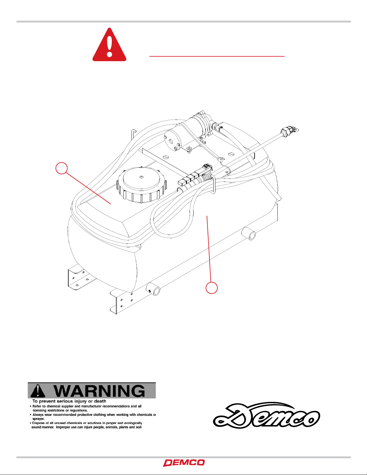
WARNING: TO AVOID PERSONAL INJURY OR PROPERTY DAMAGE, OBSERVE
FOLLOWING INSTRUCTIONS:
Chemicalsaredangerous.Knowexactlywhatyou’regoingto doand whatis
going to happen before attempting to work with these products. Improper
selection or use can injure people, animals, plants and soil.
Alwayswear protectiveclothing suchas coveralls,gogglesandgloves when
working with chemicals or sprayer.
Be sure to dispose of all unused chemicals or solutions in a proper and eco-
logically sound manner.
Table of Contents
General information................................................................................................................... 2
Safety, Signal Words .................................................................................................................. 3
Equipment Safety Guidelines ................................................................................................... 4
Lighting and Marking ................................................................................................................ 4
Safety Sign Care ......................................................................................................................... 4
Safety Sign Locations................................................................................................................. 5
Transport Operations................................................................................................................. 6
Remember .................................................................................................................................. 6
Before Operation ....................................................................................................................... 6
During Operation....................................................................................................................... 7
Following Operation.................................................................................................................. 7
Performing Maintenance........................................................................................................... 8
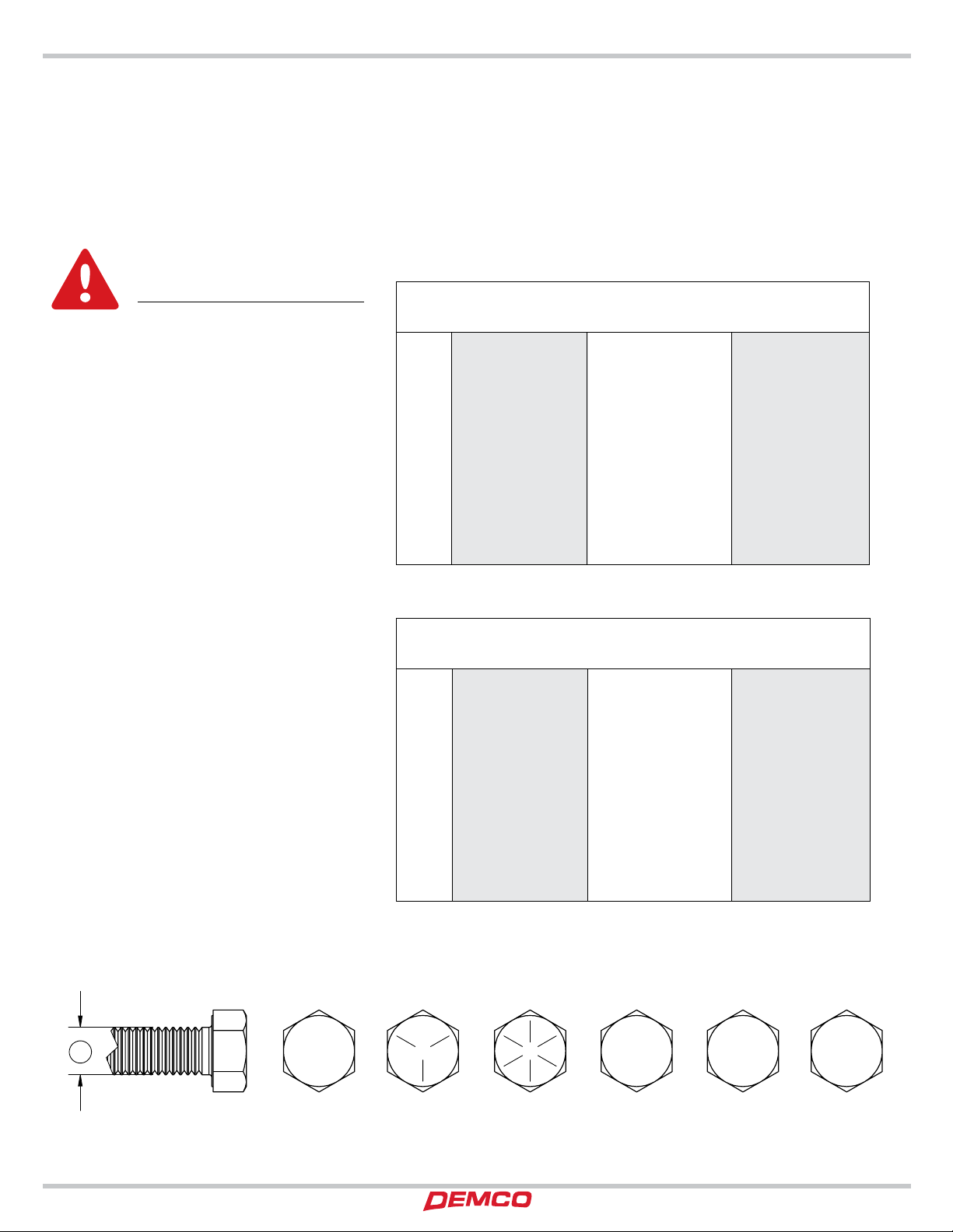
Bolt Torque.................................................................................................................................. 9
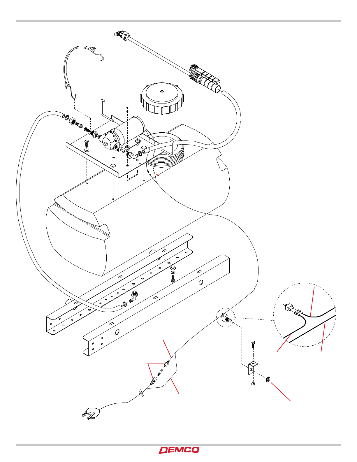
14 Gallon Sprayer (SM14) Breakdown and Parts List......................................................... 10-11
14 Gallon Sprayer (SM314) Breakdown and Parts List ...................................................... 12-13
HYMB Mounting Brackets ........................................................................................................ 14
Secondary Tank Option Parts Breakdown.............................................................................. 14
80” Boom Assembly (80B10) Breakdown and Parts List ..................................................... 15
12’ Boom Assembly (144-B14) Breakdown and Parts List ................................................... 16
Electric Pump breakdown and Parts List ............................................................................... 17
Sprayer Calibration ................................................................................................................... 18
Sprayer Checklist ...................................................................................................................... 19
WARRANTY POLICY, OPERATOR MANUALS, PARTS MANUALS & REGISTRATION
Go online to www.demco-products.com to review Demco warranty policies, operator manuals and register your Demco
product.
Introduction

AS20005 Page 3
TAKE NOTE! THIS SAFETY ALERT SYMBOL FOUND THROUGHOUT THIS
MANUAL IS USED TO CALL YOUR ATTENTION TO INSTRUCTIONS INVOLVING
YOUR PERSONAL SAFETY AND SAFETY OF OTHERS. FAILURE TO FOLLOW
THESE INSTRUCTIONS CAN RESULT IN INJURY OR DEATH.
THIS SYMBOL MEANS
ATTENTION
BECOME ALERT
YOUR SAFETY IS INVOLVED!
SIGNAL WORDS
This manual uses of the following signal words--
DANGER, WARNING, and CAUTION-- with safety
messages. The appropriate signal word has been
selected using the following guidelines.
DANGER:
Indicates an imminently hazardous situation
that, if not avoided, will result in death or serious
injury. This signal word is to be limited to the
most extreme situations typically for machine
components which, for functional purposes,
cannot be guarded.
WARNING:
Indicates a potentially hazardous situation that,
if not avoided, could result in death or serious
injury, and includes hazards that are exposed
when guards are removed. It may also be used
to alert against unsafe practices.
CAUTION:
Indicates a potentially hazardous situation that,
if not avoided, may result in minor or moderate
injury. It may also be used to alert against unsafe
practices.
If you have questions not answered in this manual , require additional copies, or if your manual is
damaged, please contact your dealer or Demco, 4010 320th Street, Boyden, IA 51234 ph: (712)
725-2311 or Toll Free: 1-800-543-3626 Fax: (712) 725-2380 http://www.demco-products.com
Safety

Page 4 AS20005
SAFETY...YOU CAN LIVE WITH IT
EQUIPMENT SAFETY GUIDELINES
Every year many accidents occur which could have been avoided by a few seconds of thought and a more careful
approach to handling equipment. You, the operator, can avoid many accidents by observing the following
precautions in this section. To avoid personal injury, study the following precautions and insist those working
with you, or you yourself, follow them.
In order to provide a better view, certain illustrations in this manual may show an assembly with a safety shield
removed. However, equipment should never be operated in this condition. Keep all shields in place. If shield
removal becomes necessary for repairs, replace shield prior to use.
Replace any caution, warning, danger or instruction safety decal that is not readable or is missing. Location of
such decals is indicated in this booklet.
Do not attempt to operate this sprayer under the influence of alcohol or drugs.
Review safety instructions with all users.
Operator should be a responsible adult. DO NOT ALLOW PERSONS TO OPERATE OR ASSEMBLE THIS UNIT
UNTIL THEY HAVE DEVELOPED A THOROUGH UNDERSTANDING OF SAFETY PRECAUTIONS AND HOW
IT WORKS.
Do not paint over, remove, or deface any safety signs or warning decals on your sprayer. Observe all safety
signs and practice instructions on them.
Never exceed limits of a piece of machinery. If its ability to do a job, or to do so safely is in question-DON’T
TRY IT.
LIGHTING AND MARKING
It is the responsibility of customer to know lighting and marking requirements of local highway authorities and
to install and maintain sprayer to provide compliance with regulations. Add extra lights when transporting at
night or during periods of limited visibility.
SAFETY SIGN CARE
• Keepsafetysignscleanandlegibleatalltimes.
• Replacesafetysignsthataremissingorhavebecomeillegible.
• Replacementpartsthatdisplayedasafetysignshouldalsodisplaycurrentsign.
• Safetysignsareavailablefromyourdistributor,dealerpartsdepartment,orfactory.
How to install safety signs:
• Besurethatinstallationareaiscleananddry.
• Decideonexactpositionbeforeyouremovebackingpaper.
• Removesmallestportionofsplitbackingpaper.
• Aligndecaloverspeciedareaandcarefullypresssmallportionwith
exposed sticky backing in place.
• Slowlypeelbackremainingpaperandcarefullysmoothdecalintoplace.
• Airpocketscanbepiercedwithapinandsmoothedoutusingpieceofbackingpaper.
Safety

AS20005 Page 5
SAFETY SIGN LOCATIONS
Types of safety sign and locations on equipment are shown in illustration below. Good
safety requires that you familiarize yourself with various safety signs, type of warning, and
area or particular function related to that area, that requires your SAFETY AWARENESS.
A
B
A. AB21014 - Warning: Refer to chemical
supplier and manufacturer Qty. 1
B. AA21012 - Small Demco Qty. 2
Safety Signs

Page 6 AS20005
BEFORE OPERATION:
• Carefullystudyandunderstandthismanual.
• Donotwearloose-ttingclothingwhichmaycatchinmovingparts.
• Alwayswearprotectiveclothingandsubstantialshoes.
• Itisrecommendedthatsuitableprotectivehearingandeyeprotectionbeworn.
• Theoperatormaycomeincontactwithcertainmaterialswhichmayrequirespecicsafetyequipmentrelative
to handling of such materials. (Examples: extremely dusty, molds, fungus, bulk fertilizers, etc.)
• Givesprayeravisualinspectionforanyloosebolts,wornparts,orcrackedwelds,andmakenecessaryrepairs.
Follow maintenance safety instructions included in this manual.
• Besuretherearenotoolslyingonorinequipment
• Donotusesprayeruntilyouaresurethatareaisclear,especiallyaroundchildrenandanimals.
• Don’thurrylearningprocessortakesprayerforgranted.Easeintoitandbecomefamiliarwithyournew
equipment.
• Practiceoperationofyourequipmentanditsattachments.Completelyfamiliarizeyourselfandother
operators with its operation before using.
TRANSPORT OPERATIONS
• Adoptsafedrivingpractices:
- Always drive at a safe speed relative to local conditions and ensure that your speed is low enough for an
emergency stop. Keep speed to a minimum.
- Reduce speed prior to turns to avoid risk of overturning.
- Always keep ATV in gear to provide engine braking when going downhill. Do not coast.
- Do not drink and drive!
• ComplywithstateandlocallawsgoverningtheuseofATV’s.DonotusetheATVonhighwayandstreetsif
prohibited.
• UseapprovedaccessorylightingandagsandnecessarywarningdevicesifusingtheATVonstreetsor
highways. Always use flashing amber lights or slow moving vehicle emblem if operating on streets or
highways.
• Useofashingamberlightsisacceptableinmostlocalities.However,somelocalitiesprohibittheiruse.
Local laws should be checked for all highway lighting and marking requirements.
• Beasafeandcourteousdriveratalltimes.
• Watchforobstructionsoverheadandsidetosidewhiletransporting.
• AlwaysoperateyourATVinapositiontoprovidemaximumvisibilityatalltimes.Makeallowancesforincreased
length and weight of sprayer when making turns, stopping, etc.
REMEMBER
Your best assurance against accidents is a careful and responsible operator. If there is any portion of this
manual or function you do not understand, contact your local authorized dealer or manufacturer.
Safety

AS20005 Page 7
DURING OPERATION
• Bewareofbystanders,PARTICULARLY CHILDREN! Always look around to make sure that it is safe to start
engine of towing vehicle or move sprayer. This is particularly important with higher noise levels and quiet
cabs,
as you may not hear people shouting.
•NO PASSENGERS ALLOWED- Do not carry passengers anywhere on sprayer.
• Keephandsandclothingclearofmovingparts.
• Donotclean,lubricate,oradjustyoursprayerwhileitismoving.
• Whenhaltingoperation,evenperiodically,setvehiclesbrakes,shutoffengine,and remove ignition key.
• Beespeciallyobservantofoperatingareaandterrain-watchforholes,rocks,orotherhiddenhazards.
Always inspect area prior to operation.
- DO NOT operate near edge of drop-offs or banks.
- DO NOT operate on steep slopes as overturn may result.
- Operate up and down (not across) intermediate slopes. Avoid sudden starts and stops.
• Pickthemostlevelpossibleroutewhentransportingacrosselds.Avoidedgesofditches,gullies,and
steep hillsides.
• Beextracarefulwhenworkingoninclines.
• Periodicallyclearsprayerofbrush,twigs,orothermaterialstopreventbuildupofdrycombustiblematerials.
• Maneuvertractorortowingvehicleatsafespeeds.
• Avoidloosegravel,rocks,andholes;theycanbedangerousforsprayeroperationormovement.
• Donotwalkorworkunderraisedcomponentsorattachmentsunlesssecurelysupported.
• Keepallbystanders,pets,andlivestockclearofworkarea.
• Neverstandalongsideofunitwithenginerunningorattempttostartengineand/oroperatemachinewhile
standing alongside of unit.
• Neverleaverunningequipmentattachmentsunattended.
• Asaprecaution,alwaysrecheckhardwareonequipmentfollowingevery100hoursofoperation.Correctall
problems. Follow maintenance safety procedures.
FOLLOWING OPERATION
• Followingoperation,orwhenunhitching,stoptractorortowingvehicle,setbrakes,shutoffengineand
remove ignition key.
• Storeunitinanareaawayfromhumanactivity.
• Donotparkequipmentwhereitwillbeexposedtolivestockforlongperiodsoftime.Damageandlivestock
injury could result.
• Donotpermitchildrentoplayonoraroundstoredunit.
• Makesureallparkedmachinesareonahard,levelsurfaceandengageallsafetydevices.
Safety

Page 8 AS20005
PERFORMING MAINTENANCE
• Goodmaintenanceisyourresponsibility.Poormaintenanceisaninvitationtotrouble.
• Makesurethereisplentyofventilation.Neveroperateengineoftowingvehicleinaclosedbuilding.
Exhaust fumes may cause asphyxiation.
• Beforeworkingonthismachine,stoptowingvehicle,setbrakes,disengagePTOandallpowerdrives,
shut off engine and remove ignition key.
• Becertainallmovingpartsandattachmentshavecometoacompletestopbeforeattemptingtoperform
maintenance.
•Always use a safety support and block wheels. Never use a jack to support machine.
• Alwaysusepropertoolsorequipmentforjobathand.
• Useextremecautionwhenmakingadjustments.
• Followtorquechartonpage11inthismanualwhentighteningboltsandnuts.
• Neveruseyourhandstolocateahydraulicleakonattachments.Useasmallpieceofcardboardorwood.
Hydraulic fluid escaping under pressure can penetrate skin.
• Openingsinskinandminorcutsaresusceptibletoinfectionfromhydraulicuid.
Without immediate medical treatment, serious infection and reactions can occur.
• Whendisconnectinghydrauliclines,shutoffhydraulicsupplyandrelieveallhydraulicpressure.
• Replaceall shields and guards after servicing and before moving.
• Afterservicing,besurealltools,partsandserviceequipmentareremoved.
• Donotallowgreaseoroiltobuilduponanysteporplatform.
• Whenreplacingboltsrefertoownersmanual.
• Refertobolttorquechartonpage11forheadidenticationmarking.
• Wherereplacementpartsarenecessaryforperiodicmaintenanceandservicing,genuinefactory
replacement parts must be used to restore your equipment to original specifications. Manufacturer will not
claim responsibility for use of unapproved parts or accessories and other damages as a result of their use.
• Ifequipmenthasbeenalteredinanywayfromoriginaldesign,manufacturerdoesnotacceptanyliabilityfor
injury or warranty.
• Areextinguisherandrstaidkitshouldbekeptreadilyaccessiblewhileperformingmaintenanceonthis
sprayer.
Safety

AS20005 Page 9
Tighten all bolts to torques specified in chart unless otherwise noted. Check tightness of
bolts periodically, using bolt chart as guide. Replace hardware with same grade bolt.
NOTE:Unlessotherwisespecied,high-strengthGrade5hexboltsareusedthroughout
assembly of equipment.
Bolt Torque for Standard bolts *
GRADE 2 GRADE 5 GRADE 8
“A” lb-ft (N.m) lb-ft (N.m) lb-ft (N.m)
1/4” 6 (8) 9 (12) 12 (16)
5/16” 10 (13) 18 (25) 25 (35)
3/8” 20 (27) 30 (40) 45 (60)
7/16” 30 (40) 50 (70) 80 (110)
1/2” 45 (60) 75 (100) 115 (155)
9/16” 70 (95) 115 (155) 165 (220)
5/8” 95 (130) 150 (200) 225 (300)
3/4” 165 (225) 290 (390) 400 (540)
7/8” 170 (230) 420 (570) 650 (880)
1” 225 (300) 630 (850) 970 (1310)
Torque figures indicated are valid for
non-greased or non-oiled threads
and heads unless otherwise specified.
Therefore, do not grease or oil bolts or
capscrews unless otherwise specified
in this manual. When using locking
elements, increase torque values
by 5%.
* GRADE or CLASS value for bolts
and capscrews are identified by their
head markings.
Torque Specifications
CLASS 8.8 CLASS 9.8 CLASS 10.9
“A” lb-ft (N.m) lb-ft (N.m) lb-ft (N.m)
6 9 (13) 10 (14) 13 (17)
7 15 (21) 18 (24) 21 (29)
8 23 (31) 25 (34) 31 (42)
10 45 (61) 50 (68) 61 (83)
12 78 (106) 88 (118) 106 (144)
14 125 (169) 140 (189) 170 (230)
16 194 (263) 216 (293) 263 (357)
18 268 (363) -- -- 364 (493)
20 378 (513) -- -- 515 (689)
22 516 (699) -- -- 702 (952)
24 654 (886) -- -- 890 (1206)
Bolt Torque for Metric bolts *
*5$'(
&/$66
&/$66
*5$'( *5$'(
&/$66
$
Bolt Torque
Torque Data for Standard Nuts, Bolts and Capscrews

Page 10 AS20005
39
4
5
6
6
7
8
9
10
11
12
13
14
15 161718
19
20
21
22
23
24
25
26
27
28
29
32
33
19
20 30
38
37
34
31
35
1
2
3
Positive Wire
Negative Wire
36
36
Positive Wire
Positive Wire
Negative Wire
Included with switch
Parts Breakdown
14 Gallon Sprayer (SM14)

AS20005 Page 11
Parts List
14 Gallon Sprayer (SM14) Parts List
ITEM PART # DESCRIPTION QTY
109244 REPLACEMENTFUSEHOLDER 1
209272 REPLACEMENT20AMPFUSE 1
3B6PH HOSE CLAMP .375 NYLON 2
4380RB .375I.D.RUBBERSHOSE(15’) -
504742 SHORTRUBBERTARPSTRAP 1
604658 S-HOOK FOR TARP STRAP 2
702205 #10-24UNCNYLONINSERTLOCKNUT 4
807490 .50 OD X .19” ID FLATWASHER 4
98000 543 150 12VOLTELECTRICPUMP 1
10 EL3838 .375 MPT X .375 HOSE BARB ELBOW 1
11 04824 #10-24UNCSPECIALU-BOLT(2.0625WIDE) 2
12 00622 .25-10UNCX.50LGFLATHEADSLOTTEDCAPSCREW 4
13 04747-80 PUMPANDBATTERYMOUNT 1
14 8027 SWIVELNUT 1
15 K8400 1/2 .50 HOSE BARB 1
16 8079NY 50 MESH POLYPROPYLENE STRAINER 1
17 NB1614 .375 MPT X .25 MPT STRAINER FITTING 1
18 RB3814 .375MPTX.25FPTREDUCERFITTING 1
19 B8PH .50 HOSE CLAMP NYLON 2
20 120RB .50I.D.RUBBERHOSE(36”) -
21 P14 14 14GALLONTANK(LIDINCLUDED) 1
22 PL5A TANK LID ONLY -
23 BEL1212 .50 MPT X .50 HOSE BARB ELBOW (GFP) 1
24 04746-80 MAINFRAMEWITHBUSHINGS 1
25 04745-80 MAIN FRAME 1
26 00004 .3125 FLAT WASHER 6
27 00036 .3125 LOCKWASHER 6
28 05961 .3125-18UNCX.625HEXHEADBOLTGR.5 6
29 04764 14-2 STAND X 8’ WIRE HARNESS w/BATTERY CLAMPS (10’) 1
30 01013 SWTICH 1
31 04755-95 SWITCHMOUNT 1
32 02447 RED BATTERY CLMAP 1
33 02448 BLACK BATTERY CLAMP 1
34 04055 BOLT, .25 NC HEX HEAD (NOT SHOWN) 1
35 02772 LOCKNUT.25NCNYLON(NOTSHOWN) 1
36 05004 CONNECTOR, SPADE 2
37 05020 SPADEENDS-PUMP 2
38 05021 SPADE ENDS - WIRE HARNESS 2
39 12217 15”POLYHANDGUNw/TIP 1
-5500 18PP REPLACEMENT TIP STRAIGHT (NOT SHOWN) -
Please order replacement parts by PART NO. and DESCRIPTION.

Page 12 AS20005
2
4
5
6
7
8
9
10
11
12
13
14
15
16
17
18
19
23
24
25
26
27
28
29
20
30
1
3
Positive Wire
Negative Wire
17
15
Negative Wire
To Sprayer Boom
37
36 36
39
38
32 33
40
41
21
21
21
22
22
22
22
22 22
22
Parts Breakdown
14 Gallon Sprayer (SM314)

AS20005 Page 13
ITEM PART # DESCRIPTION QTY
100004 WASHER, FLAT, .313 6
200036 WASHER LOCK 0.313 6
300622 SCREW, .25NC X .50 FLAT HEAD SLOT 4
402205 NUT,#10NCNYLONINSERT 4
503900 VALVE, BRASS, .375” FPT (2X), 2 WAY 1
604745 14 GALLON TANK BOTTOM CHANNEL 1
704746 MAIN FRAME HALF-SM14 1
804747 PUMPANDBATTERYMOUNT 1
904824 #10-24U-BOLT,2”SPECIAL 2
10 05020 BULLETCONNECTORF/16-14GA 2
11 05961 BOLT, .313 NC X .625 HEX HEAD GR5 6
12 07490 WASHER, .190-.200 I.D. X.50 O.D. 4
13 120RB 1/2”RUBBERHOSE 4FT
14 12217 15” SPRAY WAND POLY W/ TIP 1
-5500 18PP REPLACEMENT TIP STRAIGHT (NOT SHOWN)
15 2088 343 135 12VDC3.6GPMPUMP 1
16 23120PP VALVE,PRESSURERELIEF,1/2” 1
17 380RB 3/8”RUBBERHOSE 20FT
18 60GB GAUGEBRASS60# 1
19 A1212SF FTG STR .50 FPT X .50 HB SWIVEL 1
20 A3838 FTG, .375 MPT X .375 HB 1
21 B6PH CLAMP, NYLON FOR .375 HOSE 3
22 B8PH CLAMP, NYLON FOR .5 HOSE 8
23 BA1212 FTG, STR, .50” MPT X .50” HB. GFP 1
24 BEL1212 FTG, ELB, .5”MPT X .5” HB, GFP 1
25 BM1238 FTG, STR, .50” MPT X .375”HB 1
26 BTT12G FTG, TEE, .50” FPT W/ .25 FPT 1
27 EL1438 FTG, ELB, .25” MPT X .375”HB 1
28 P14 14 TANK14GALLONPOLY(LIDINCLUDED) 1
-PL5A REPLACEMENT LID -
29 RVB12 80 STRAINER, .50” X 80 MESH 1
30 T12 FTG TEE .50 HB POLY 1
31 04755-95 SWITCHMOUNT(NOTSHOWN,SEEPAGE10) 1
32 02447 RED BATTERY CLMAP 1
33 02448 BLACK BATTERY CLAMP 1
34 04055 BOLT, .25 NC HEX HEAD (NOT SHOWN) 1
35 02772 LOCKNUT.25NCNYLON(NOTSHOWN) 1
36 05004 CONNECTOR, SPADE 2
37 05021 CONNECTOR, SPADE 2
38 01013 SWITCH 1
39 04764 10’ WIRE HARNESS W/ CLAMPS 1
40 09244 FUSEHOLDER 1
41 09272 FUSE20AMP 1
Please order replacement parts by PART NO. and DESCRIPTION.
Parts List

Page 14 AS20005
NOTE: Item No.2 may not be required on all units.
REF. PART REQ’D
NO. NO. QTY. DESCRIPTION
EX14KT PARTS LIST
1. BEL1212 1
1/2”MPT x 1/2” Hose Barb Elbow (GFP)
2. T12 1 1/2” Hose Barb Tee
3. B8PH 4 1/2” Plastic Hose Clamp
4. P14 14 1 14 Gal. Poly. Tank w/Lid
5. 04745-70 1 Frame Rail
6. 04746-70 1 Frame Rail w/Bushing
7. 120RB - 1/2” ID Rubber Hose (5’ Req’d))
- HYMB 1 Mounting Kit (parts listed above)
SECONDARY TANK OPTION PARTS BREAKDOWN
1
1
2
2
3
4
4
4
1
1
5
5
6
6
1
3
3
4
5
6
7
HYMB
MOUNTING KIT
3
2
Feeder Line of Existing Tank
Please order replacement parts by PART NO. and DESCRIPTION.
REF. PART REQ’D
NO. NO. QTY. DESCRIPTION
HYMB MOUNTING BRACKETS PARTS LIST
3
1. 02441-95 4 Mounting Clamp
2. 02440-95 2 Mounting Bar
3. 02990 4 5/16”-18UNCx1”HexHd.Bolt
4. 00372 4 5/16”-18UNCx1-1/2”HexHd.Bolt
5. 00036 4 5/16” Lockwasher
6. 02802 4 5/16”-18UNCNylonInsertLocknut
HYMB Mounting Brackets
Honda, Kawasaki, Ploaris & Yamaha with Luggage Rack

AS20005 Page 15
- B11 114 2 1-1/4” Boom Clamp Assembly
16. 00062 1 1/4”-20UNCHexNut
17. 00337-95 2 1-1/4” Boom Clamp
18. 00068 1 1/4”-20UNCx3/4”HexBolt
19. 4193 A PP50 2 5 PSI Ball Check Strainer
20. AN1.5 2 Flood Jet Spray Tip (Blue)
21. 8027 2 11/16” FPS Swivel Nut
22. B12 2 Nozzle Nut
23. 02678-95 2 Boom Mounting Plate
24. 00909 2 5/16”-18UNCx1-1/4”Sq.U-bolt
25. 00004 4 5/16” Flatwasher
26. 02802 4 5/16”-18UNCNylonInsertLocknut
27. 02253-10 1 Boom Tube
1. 380RB - 3/8” I.D. Rubber Hose (5’)
2. B6PH 7 3/8” Hose Clamp
3. A3838 1 3/8” MPT x 3/8” Hose Barb
4. 03900 1 3/8” FPT x 3/8” FPT Valve
5. EL1238 1 1/2” MPT x 3/8” Hose Barb Elbow
6. BTT12 1 1/2” FPT Tee
7. BM1238 2 1/2” MPT x 3/8” MPT Nipple Fitting
8. 00095 2 3/8”-16UNCx3/4”Sq.Hd.SetScrew
9. 02274-70 2 Mounting Pipe
10. NHT11 1 Hose Tie
11. T38 1 3/8” Hose Barb Insert Tee
12. 00955 2 1/4”-20UNCRoundU-bolt
13. 02772 4 1/4”-20UNCNylonInsertLocknut
14. 00214 4 1/4” Flatwasher
15. NTL38 2 3/8” Elbow Spray Nozzle Ftg. (w/nut)
Please order replacement parts by PART NO. and DESCRIPTION.
REF. PART REQ’D
NO. NO. QTY. DESCRIPTION
OPTIONAL
80” BOOM ASSEMBLY (80B10) PARTS LIST
REF. PART REQ’D
NO. NO. QTY. DESCRIPTION
NOTE: Use thread sealant on
all threaded fittings.
8
9
9
10
11
12
12
13
13
16
14
14
15
17
18
2
2
2
2
19
20 21
22
23
24
24
25
26
1
1
2
2
3
47
5
6
7
23
27
Parts Breakdown
14 Gallon Sprayer (SM14) with Optional 80” Boom Assembly (80B10)

Page 16 AS20005
1. 02678-95 2 Boom Mounting Plate
2. 00909 2 5/16”-18UNCx1-1/2”SquareU-bolt
3. 00004 4 5/16” Flatwasher
4. 02802 4 5/16”-18UNCNylonInsertLocknut
5. 04822 2 1/4”-20UNCx1-1/2”RoundU-bolt
6. 00214 4 1/4” Flatwasher
7. 02772 4 1/4”-20UNCNylonInsertLocknut
8. 02274-70 2 Mounting Pipe
9. 02636-10 1 Center Boom Section
10. 02637-10 1 Right Boom Section
11. 02638-10 1 Left Boom Section
12. 00340-95 2 Wing Hinge Pin (includes two 11137)
13. 11137 2 3/8” Clinch Nut (incl’d with 00340-95)
14. 01564 2 Spring
15. 00357 2 3/8”-16UNCx4-1/2”TensionBolt
16. 02592 2 3/8”-16UNCNylonInsertLocknut
17. T38 1 3/8” Insert Tee
18. B6H 8 3/8” Gear Clamp
19. 380RB - 3/8” I.D. Rubber Hose
20. NHT11 5 Hose Tie
21. NTT38 2 3/8” Tee Nozzle Fitting w/nut
B11 114 4 1-1/4” Boom Clamp Assembly
22. 00337-95 2 1-1/4” Boom Clamp
23. 00068 1 1/4”-20UNCx3/4”HexHd.Bolt
24. 02772 1 1/4”-20UNCNylonInsertLocknut
25. 4193APP50 4 5 PSI Ball Check Valve
26. AN1.5 4 Flood Jet Spray Tip
27. 8027 4 11/16” FPS Swivel Nut
28. NTL38 2 3/8” Elbow Spray Nozzle Fitting w/nut
12’ BOOM (144B14) PARTS LIST
REF. PART REQ’D
NO. NO. QTY. DESCRIPTION
REF. PART REQ’D
NO. NO. QTY. DESCRIPTION
Please order replacement parts by PART NO. and DESCRIPTION.
NOTE: Use thread sealant on
all threaded fittings.
18
33
31
32
30 33
19
29
18
18
19
18
34
11
12
14
15
819
20
13
20
28
18
23
24
25
27
36 26
22
21
22 25
27
36
26
24
23
19
18
1718
8
9
5
2
3
4
5
2
1
16
16
7
67
10
37
38
29. A3838 1 3/8”MPT x 3/8” Hose Barb
30. 03900 1 3/8”FPT x 3/8”FPT Valve
31. EL1238 1 1/2”MPT x 3/8” Hose Barb Elbow
32. BTT12 1 1/2”FPT Tee (GFP)
33. BM1238 2 1/2”MPT Nipple Fitting
34. 00095 2 3/8”-16UNCSq.Hd.SetScrew
35. B6PH 2 3/8” Gear Clamp
36. B12 4 Nozzle Nut
37. 00640 2 1/2”-13UNCJamNut
38. 00967 2 1/2”-13UNCx1-1/4”HexHeadBolt
12’ Boom Assembly (144B14) Parts Breakdown

AS20005 Page 17
2
4
5
2
4
5
6
3
PART NO. 8000 543 150
12VDCcontinuousdutymotorandpositivedisplacement
diaphragm pump. Pump is equipped with viton valves,
santoprene diaphragm, and will bypass liquid at 45 PSI.
1.5 GPM maximum discharge. 3/8” FPT ports.
8000 543 150 - 1.5GPM ELECTRIC PUMP PARTS LIST
ITEM PART # DESCRIPTION
1. 94 382 09 Pumphead complete w/ viton parts
2. 94 378 00 UpperHousingKit
3. 94 391 09 Viton Valve Kit w/45 PSI by-pass
4. 94 395 06 Santoprene Diaphragm Kit
5. 94 385 03 Lower Housing Drive Assembly 3.0 degree Cam
6. 94 370 03 Motor Assembly
Please order replacement parts by PART NO. and DESCRIPTION.
2088 343 135 -
3GPM ELECTRIC PUMP PARTS LIST
ITEM PART # DESCRIPTION
2. 94 230 36 Switch Assembly
4. 94 231 30 UpperHousingKit
5. 94 232 05 Viton Valve Kit
Please order replacement parts by PART NO. and
DESCRIPTION.
Parts Breakdown
Electric Pump

Page 18 AS20005
DOUBLE
OVERLAP
10 .15 11.2 7.5 5.6 4.5 3.7 3.2 2.8
20 .21 15.8 10.5 7.9 6.3 5.3 4.6 3.9
30 .26 19.4 12.9 9.7 7.7 6.4 5.6 4.8
40 .30 22.2 14.8 11.1 8.9 7.4 6.5 5.6
.05 300 .20 75
.06 250 .225 67
.07 214 .25 60
.08 188 .30 50
.09 167 .35 43
.10 150 .40 38
.11 136 .50 30
.12 125 .60 25
.13 115 .70 21
.14 107 .80 19
.15 100 .90 17
.17 88 1.0 15
seconds seconds
GPM to collect 1 qt. GPM to collect 1 qt.
RATES OF FLOW...for calibrating spray tips.
Use the following formula to determine your ratio per acre.
GPA - Gallons Per Acre
GPM - Gallons Per Minute
MPH - Miles Per Hour
5940 x GPM (Per Nozzle)
MPH x W*
* W - Nozzle spacing in inches.
GPA =
Important: Replace all worn tips and those with streaky or uneven patterns.
Liquid Capacity
Pressure 1 Nozzle
in in 2 3 4 5 6 7 8
Tip No. PSI GPM MPH MPH MPH MPH MPHMPH MPH
GALLONS PER ACRE
40” TIP SPACING
AN1.5
Spray Tip Chart for 80” and 144” Booms
There is not a standard spray height for FloodJet tips. Raise or
lower the spray boom. . . or rotate nozzle tips to double overlap
spray patterns and provide optimum coverage along spray
boom.
When switching from one chemical to another chemical in the
sprayer where contamination must be prevented, wash out with
ammonia and water through the tank, pump and all hose. Then
flush with water two or three times. Herbicides such as 2-4-D are
hard to remove. After using them, follow the special cleaning
procedures noted on the pesticide label.
3.0 23 45 68
4.0 17 34 51
5.0 14 27 41
6.0 11 23 34
7.0 9.7 19 29
8.0 8.5 17 26
10 6.8 14 20
speed in MPH
(miles per hr.) 100 feet 200 feet 300 feet
VEHICLE SPEEDS
Mark off a distance of 100, 200 or 300 feet. Run the lawn mower
or all terrain vehicle over this distance, carefully marking the
throttle setting or speedometer reading. To make measurement
of test run, begin from a standing start far enough ahead of the
first marker so that your rig is at full speed before traveling the
100, 200 or 300 foot distances.
time required in SECONDS to travel:
*approximately 13-1/2” for 30” coverage.
*approximately 15” for 40” coverage.
This tip (LP015 110) is specially designed to operate at low
pressure, and wide angle allowing the boom to be run close
to the ground for less spray drift.
TIP
SPACING
30%
OVERLAP
*SPRAY
HEIGHT
TIP
SPACING
Calibration Instructions

AS20005 Page 19
Downtimein fieldscausedby fieldbreakdownsiscostlyand timeconsuming.Many breakdowns
can be eliminated by periodic equipment maintenance. By spending a little time running over
this checklist before seasonal spraying application time and following proper after-season care,
you can save time and money later on.
Check Before Going To The Field :
NOTE: Demco does not and will not make any recom-
mendationsconcerningtheapplication of various
chemicals or solutions. These recommendations
relate to either amount or procedure of materials
applied. If you have any questions regarding ap-
plicationof certainchemicalsor solutions,contact
your chemical supplier and follow chemical
manufacturer recommendations.
1. NOZZLES
Check tip for excessive wear by checking for grooves
in or near tip opening. Check nozzle spacing by start-
ing at center and working outwards. Check boom for
proper height.
2. HOSES
Check all hoses for worn or soft spots. Be sure all hose
clamps are tightened and hoses are not kinked or
pinched. Check for leakage in any lines.
3. TANK
Remove and clean agitator orifices. Check orifices
for excessive wear by checking for grooves in or near
orifice opening.Inspect fitting and grommets to insure
they are in good condition.
4. CONTROLS
Check for leakage, plugging, or wear on all valves, fit-
tings, etc. Clean off any build up of foreign material.
5. PUMP
Check to be sure pump turns freely.
6. FRAME
Be sure all bolts are tightened.
7. REPLACEMENT PARTS
Replace all worn or damaged parts.
After Season Care:
NOTE: It is important that when cleaning sprayer you
wear proper safety equipment.See your chemical
or fertilizer package for this information.
1. After spraying chemicals,run water mixed with clean-
ers through tank, pump and all hose hookups. If wet-
table powder dries out in system, it is very difficult to
put back into suspension and can cause malfunction,
damage or injury.
2. When cleaned, tank should have all openings closed
or covered to keep dirt from blowing in.
3. Pump should be flushed with soluble oil and pump
ports plugged to keep out moisture and air.
4. Disassemble tips and rinse with water or cleaning
solution. (Appropriate for chemical sprayed).
5. Clean tip opening with a wooden toothpick. Never
use wire or a hard object that could distort opening.
6. Besuretodisposeof allunused chemicalsor solutions
in a proper and ecologically sound manner.
7. Water rinse and dry tips before storing.
• Keephands,feet,andlooseclothingawayfromrotatingparts.
• Wearprotectiveclothingrecommendedbyyourchemicaland
fertilizer manufacturer when working with chemicals.
WARNING: To Prevent Serious Injury Or Death
!
Sprayer Checklist

Other manuals for SM14
1
This manual suits for next models
1
Table of contents
Other Demco Paint Sprayer manuals
Popular Paint Sprayer manuals by other brands

Durr
Durr EcoGun 249 Operation manual

WALTHER PILOT
WALTHER PILOT PILOT WA 905 operating instructions

F5
F5 Paint Shaker Installation and instruction manual

Generac Power Systems
Generac Power Systems Dust Fighter DF Smart user guide

AirCom
AirCom HT Series instruction manual

Goizper Group
Goizper Group DESHERBAGE TOTAL-7 instruction manual