manuals.online logo
Brands
  1. Home
  2. •
  3. Brands
  4. •
  5. Demco
  6. •
  7. Paint Sprayer
  8. •
  9. Demco RM Series User manual

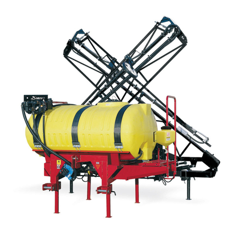
Demco RM Series User manual

AC20047, Rev 6
12/17
SPRAYERS
Rear Mount 150 & 200 Gallon
Page 2 AC20047
Thank you for purchasing a Demco sprayer. We feel you have made a wise choice and hope you are completely
satisfied with your new piece of equipment.
If you have any questions regarding the applications of certain solutions or chemicals, contact your chemical supplier
and follow chemical manufacturer recommendations as well as all licensing and use restrictions or regulations.
General Information................................................................................................................... 2
Safety Information ....................................................................................................................3-10
Bolt Torque................................................................................................................................. 10
Tank Installation......................................................................................................................... 11
Rear Mount Single Section Plumbing.................................................................................. 12-13
Rear Mount Three Section Plumbing................................................................................... 14-15
Centrifugal Pump Plumbing ................................................................................................... 16
Optional Single Section Electric Solenoid Controls Parts Breakdown w/ Parts List.......... 17
Optional Three Section Electric Solenoid Controls Parts Breakdown w/ Parts List........... 17
Valve Mounting and Location.................................................................................................. 18
Rear Mount to Tractor Three Point .......................................................................................... 19
Rear Mount 150 and 200 Parts Breakdown and List ............................................................. 20
C7560D or XL7560D Roller Pump Breakdown ..................................................................... 21
Direct-O-Valve Breakdown....................................................................................................... 21
Tee Valve Breakdown................................................................................................................ 21
DB1 Boom Mounting Breakdown and Boom Jet Nozzle Mounting................................... 22
Sprayer Checklist....................................................................................................................... 23
INTRODUCTION
WARRANTY POLICY, OPERATOR MANUALS, PARTS MANUALS & REGISTRATION
Go online to www.demco-products.com to review Demco warranty policies, operator manuals and register your Demco
product.
Chemicals are dangerous. Know exactly what you’re going to do and what is going
to happen before attempting to work with these products. Improper selection or use
can injure people, animals, plants and soil.
Always wear protective clothing such as coveralls, goggles and gloves when working
with chemicals or the sprayer.
Be sure to dispose of all unused chemicals or solutions in a proper and ecologically
sound manner.
WARNING: TO AVOID PERSONAL INJURY OR DEATH, OBSERVE FOLLOWING INSTRUCTIONS:
GENERAL INFORMATION
1. Unless otherwise specified, high-strength (grade5)
(3 radial-line head markings) hex head bolts are used
throughout assembly of this piece of equipment.
2. Whenever terms “LEFT” and “RIGHT” are used in this
manual it means from a position behind sprayer and
facing forward.
3. When placing a parts order, refer to this manual for
proper part numbers and place order by PART NO. and
DESCRIPTION.
TABLE OF CONTENTS
AC20047 Page 3
TAKE NOTE! THIS SAFETY ALERT SYMBOL FOUND THROUGHOUT THIS
MANUAL IS USED TO CALL YOUR ATTENTION TO INSTRUCTIONS INVOLVING YOUR
PERSONAL SAFETY AND SAFETY OF OTHERS. FAILURE TO FOLLOW THESE INSTRUCTIONS
CAN RESULT IN INJURY OR DEATH!
THIS SYMBOL MEANS
ATTENTION
BECOME ALERT
YOUR SAFETY IS INVOLVED!
DANGER:
Indicates an imminently hazardous situation that, if not
avoided, will result in death or serious injury. This signal
word is to be limited to most extreme situations typically
for machine components which, for functional purposes,
cannot be guarded.
WARNING:
Indicates a potentially hazardous situation that, if not
avoided, could result in death or serious injury or death,
and includes hazards that are exposed when guards are
removed. It may also be used to alert against unsafe
practices.
CAUTION:
Indicates a potentially hazardous situation that, if not
avoided, may result in minor or moderate injury. It may also
be used to alert against unsafe practices.
If you have questions not answered in this manual, require additional copies, or if your manual is damaged, please contact
your dealer or DEMCO, 4010 320th Street, Boyden, IA 51234
ph: (712) 725-2311 or Toll Free: 1-800-543-3626 Fax: (712) 725-2380 or 1-800-845-6420
http://www.demco-products.com
SIGNAL WORDS:
This manual uses the following signal words--DANGER,
WARNING, and CAUTION-- with safety messages. The
appropriate signal word has been selected using the
following guidelines.
SAFETY
Page 4 AC20047
SAFETY...YOU CAN LIVE WITH IT
SAFETY
EQUIPMENT SAFETY GUIDELINES
Every year many accidents occur which could have been avoided by a few seconds of thought and a more
careful approach to handling equipment. You, the operator, can avoid many accidents by observing the
following precautions in this section. To avoid personal injury, study the following precautions and insist
those working with you, or you yourself, follow them.
In order to provide a better view, certain illustrations in this manual may show an assembly with a safety
shield removed. However, equipment should never be operated in this condition. Keep all shields in place.
If shield removal becomes necessary for repairs, replace shield prior to use.
Replace any caution, warning, danger or instruction safety decal that is not readable or is missing. Location
of such decals is indivated in this booklet.
Do not attempt to operate this sprayer under the influence of alcohol or drugs.
Review safety instructions with all users annually.
Operator should be a responsible adult. DO NOT ALLOW PERSONS TO OPERATE OR ASSEMBLE THIS
UNIT UNTIL THEY HAVE DEVELOPED A THOROUGH UNDERSTANDING OF SAFETY PRECAUTIONS
AND HOW IT WORKS.
To prevent injury or death, use a tractor equipped with a roll over protective system (ROPS). Do not paint
over, remove, or deface any safety signs or warning decals on your sprayer. Observe all safety signs and
practice instructions on them.
Never exceed limits of a piece of machinery. If its ability to do a job, or to do so safely is in question DON’T
TRY IT.
LIGHTING AND MARKING
It is the responsibility of customer to know lighting and marking requirements of local highway authorities
and to install and maintain sprayer to provide compliance with regulations. Add extra lights when trans-
porting at night or during periods of limited visibility.
AC20047 Page 5
DECAL PARTS LIST
A
B
C
D
DECAL LOCATION
ITEM PART # DESCRIPTION QTY
AAA21004 SMALL DEMCO 1
BAB21001 WARNING: DO NOT RIDE.... 1
CAB21002 WARNING: DO NOT STORE.... 1
DAB21014 WARNING: REFER TO CHEMICAL SUPPLIER.... 1
Please order replacement parts by PART NO. and DESCRIPTION
Page 6 AC20047
• Keepsafetysignscleanandlegibleatalltimes.
• Replacesafetysignsthataremissingorhavebecomeillegible.
• Replacementpartsthatdisplayedasafetysignshouldalsodisplaycurrentsign.
• Safetysignsareavailablefromyourdistributor,dealerpartsdepartment,orfactory.
How to install safety signs:
• Besurethatinstallationareaiscleananddry.
• Decideonexactpositionbeforeyouremovebackingpaper.
• Removesmallestportionofsplitbackingpaper.
• Aligndecaloverspeciedareaandcarefullypresssmallportionwith
exposed sticky backing in place.
• Slowlypeelbackremainingpaperandcarefullysmoothdecalintoplace.
• Airpocketscanbepiercedwithapinandsmoothedoutusingpieceofbackingpaper.
• Carefullystudyandunderstandthismanual.
• Donotwearloose-ttingclothingwhichmaycatchinmovingparts.
• Alwayswearprotectiveclothingandsubstantialshoes.
• Itisrecommendedthatsuitableprotectivehearingandeyeprotectionbeworn.
• Theoperatormaycomeincontactwithcertainmaterialswhichmayrequirespecicsafety  
equipment relative to handling of such materials. (Examples: extremely dusty, molds,
fungus, bulk fertilizers, etc.)
• Givesprayeravisualinspectionforanyloosebolts,wornparts,orcrackedwelds,andmake  
necessary repairs. Follow maintenance safety instructions included in this manual.
• Besuretherearenotoolslyingonorinequipment
• Donotusesprayeruntilyouaresurethatareaisclear,especiallyaroundchildrenand  
animals.
• Don’thurrylearningprocessortakesprayerforgranted.Easeintoitandbecomefamiliar  
with your new equipment.
• Practiceoperationofyourequipmentanditsattachments.Completelyfamiliarizeyourself  
and other operators with its operation before using.
• UseatractorequippedwithRollOverProtectionSystem(ROPS)andfastenyourseatbelt  
prior to starting engine.
• ManufacturerdoesnotrecommendusageofatractorwithROPSremoved.
SAFETY SIGN CARE
BEFORE OPERATION
SAFETY
AC20047 Page 7
• Movetractorwheelstowidestrecommendedsettingstoincreasestability.
• Donotallowanyonetostandbetweentongueorhitchandtowingvehiclewhenbackinguptosprayer.
• Bewareofbystanders,PARTICULARLY CHILDREN! Always look around to make sure that
it is safe to start engine of towing vehicle or move sprayer. This is particularly important with
higher noise levels and quiet cabs, as you may not hear people shouting.
• NOPASSENGERSALLOWED- Do not carry passengers anywhere on or in the tractor or
sprayer.
• Keephandsandclothingclearofmovingparts.
• Donotclean,lubricate,oradjustyoursprayerwhileitismoving.
• Whenhaltingoperation,evenperiodically,settractorortowingvehiclesbrakes,disengage  
PTO, shut off engine, and remove ignition key.
• Beespeciallyobservantofoperatingareaandterrain-watchforholes,rocks,orotherhidden  
hazards. Always inspect area prior to operation.
- DO NOT operate near edge of drop-offs or banks.
- DO NOT operate on steep slopes as overturn may result.
- Operate up and down (not across) intermediate slopes. Avoid sudden starts and stops.
• Pickthemostlevelpossibleroutewhentransportingacrosselds.Avoidedgesofditches,  
gullies, and steep hillsides.
• Beextracarefulwhenworkingoninclines.
• Periodicallyclearsprayerofbrush,twigs,orothermaterialstopreventbuildupofdry   
combustible materials.
• Maneuvertractorortowingvehicleatsafespeeds.
• Avoidoverheadwires.Contactwithoverheadlinescouldcauseseriousinjuryordeath.
• Avoidloosegravel,rocks,andholes;theycanbedangerousforsprayeroperationor   
movement.
• Allowforunitlengthwhenmakingturns.
• Donotwalkorworkunderraisedcomponentsorattachmentsunlesssecurelysupported.
• Keepallbystanders,pets,andlivestockclearofworkarea.
• Neverstandalongsideofunitwithenginerunningorattempttostartengineand/oroperate  
machine while standing alongside of unit.
• Neverleaverunningequipmentattachmentsunattended.
• Asaprecaution,alwaysrecheckhardwareonequipmentfollowingevery100hoursof  
operation. Correct all problems. Follow maintenance safety procedures.
DURING OPERATION
SAFETY
Page 8 AC20047
• Followingoperation,orwhenunhitching,stoptractorortowingvehicle,setbrakes,   
disengage PTO and all power drives, shut off engine and remove ignition key.
• Storeunitinanareaawayfromhumanactivity.
• Donotparkequipmentwhereitwillbeexposedtolivestockforlongperiodsoftime.Damage  
and livestock injury could result.
• Donotpermitchildrentoplayonoraroundstoredunit.
• Makesureallparkedmachinesareonahard,levelsurfaceandengageallsafetydevices.
• Adoptsafedrivingpractices:
- Keep brake pedals latched together at all times. NEVER USE INDEPENDENT BRAKING WITH MACHINE IN
TOW, LOSS OF CONTROL AND/OR UPSET OF UNIT CAN RESULT.
- Always drive at a safe speed relative to local conditions and ensure that your speed is low
enough for an emergency stop. Keep speed to a minimum.
- Reduce speed prior to turns to avoid risk of overturning.
- Always keep tractor or towing vehicle in gear to provide engine braking when going
downhill. Do not coast.
- Do not drink and drive!
• Complywithstateandlocallawsgoverninghighwaysafetyandmovementoffarmmachinery.
• Useapprovedaccessorylightingagsandnecessarywarningdevicestoprotectoperatorsofothervehicleson
highway during transport. Various safety lights and devices are available from your dealer.
• Useofashingamberlightsisacceptableinmostlocalities.However,somelocalitiesprohibittheiruse.Local
laws should be checked for all highway lighting and marking requirements.
• Whendrivingatractorandsprayerunder20mph(40kph)dayornight,useashingamber  
warning lights and a slow moving vehicle (SMV) identification emblem.
• Planyourroutetoavoidheavytrafc.
• Beasafeandcourteousdriver.Alwaysyieldtooncomingtrafcinallsituations,including  
narrow bridges, intersections, etc.
• Beobservantofbridgeloadingratings.Donotcrossbridgesratedlowerthangrossweightat 
which you are operating.
• SAFETYCHAINS:If equipment is going to be transported on a public highway, Always follow state and
local regulations regarding safety chains and auxiliary lighting. Be sure to check with local law enforcement
agencies for your own particular regulations. If required safety chains should be obtained and installed. Only
safety chains (not elastic or nylon/plastic tow straps) should be used to retain connection between towing
and towed machines in event of separation of primary attaching system. Use a high strength,
appropriately sized hitch pin with a mechanical retainer and attach safety chains. Criss cross chains under
tongue and secure to draw bar cage, mounting loops, or bumper frame.
FOLLOWING OPERATION
HIGHWAY AND TRANSPORT OPERATIONS
SAFETY
AC20047 Page 9
Your best assurance against accidents is a careful and responsible operator. If there is any portion of this
manual or function you do not understand, contact your local authorized dealer or manufacturer.
• Goodmaintenanceisyourresponsibility.Poormaintenanceisaninvitationtotrouble.
• Makesurethereisplentyofventilation.Neveroperateengineoftowingvehicleinaclosed  
building. Exhaust fumes may cause asphyxiation.
• Beforeworkingonthismachine,stoptowingvehicle,setbrakes,disengagePTOandall
power drives, shut off engine and remove ignition key.
• Becertainallmovingpartsandattachmentshavecometoacompletestopbefore
attempting to perform maintenance.
• Always use a safety support and block wheels. Never use a jack to support machine.
• Alwaysusepropertoolsorequipmentforjobathand.
• Useextremecautionwhenmakingadjustments.
• Followtorquechartonpage10inthismanualwhentighteningboltsandnuts.
• Neveruseyourhandstolocateahydraulicleakonattachments.Useasmallpieceof
cardboard or wood. Hydraulic fluid escaping under pressure can penetrate skin.
• Openingsinskinandminorcutsaresusceptibletoinfectionfromhydraulicuid.
Without immediate medical treatment, serious infection and reactions can occur.
• Whendisconnectinghydrauliclines,shutoffhydraulicsupplyandrelieveallhydraulic   
pressure.
• Replaceall shields and guards after servicing and before moving.
• Afterservicing,besurealltools,partsandserviceequipmentareremoved.
• Donotallowgreaseoroiltobuilduponanysteporplatform.
• Whenreplacingboltsrefertoownersmanual.
• RefertobolttorqueBOLT TORQUE SPECIFICATIONS for head identification marking.
• Watchforobstructionsoverheadandsidetosidewhiletransporting.
• Alwaysoperateequipmentinapositiontoprovidemaximumvisibilityatalltimes.Makeallowancesfor
increased length and weight of sprayer when making turns, stopping, etc.
REMEMBER
PERFORMING MAINTENANCE
SAFETY
Page 10 AC20047
• Replaceall shields and guards after servicing and before moving.
• Afterservicing,besurealltools,partsandserviceequipmentareremoved.
• Donotallowgreaseoroiltobuilduponanysteporplatform.
• Neverreplacehexboltswithlessthangradeveboltsunlessotherwisespecied.
• Refertobolttorquechartforheadidenticationmarking.
• Wherereplacementpartsarenecessaryforperiodicmaintenanceandservicing,genuinefactoryreplace-
ment parts must be used to restore your equipment to original specifications. The Manufacturer will not claim
responsibility for use of unapproved parts and/or accessories and other damages as a result of their use.
• Ifequipmenthasbeenalteredinanywayfromoriginaldesign,themanufacturerdoesnotacceptanyli-
ability for injury or warranty.
• Areextinguisherandrstaidkitshouldbekeptreadilyaccessiblewhileperforming  
maintenance on this equipment
Torque figures indicated are valid for non-greased or non-oiled threads and heads unless otherwise specified. Therefore, do not grease or oil
bolts or capscrews unless otherwise specified in this manual. When using locking elements, increase torque values by 5%.
* GRADE or CLASS value for bolts and capscrews are identified by their head markings.
BOLT TORQUE DATA FOR STANDARD NUTS, BOLTS, AND CAPSCREWS.
Tighten all bolts to torques specified in chart unless otherwise noted. Check tightness of bolts periodically, using bolt chart as guide.
Replace hardware with same grade bolt.
NOTE: Unless otherwise specified, high-strength Grade 5 hex bolts are used throughout assembly of equipment.
TORQUE SPECIFICATION
*5$'(
&/$66
&/$66
*5$'( *5$'(
&/$66
  
$
Bolt Torque for Standard bolts *
“A” GRADE 2 GRADE 5 GRADE 8
lb-ft (N.m) lb-ft (N.m) lb-ft (N.m)
1/4” 6 (8) 9 (12) 12 (16)
5/16” 10 (13) 18 (25) 25 (35)
3/8” 20 (27) 30 (40) 45 (60)
7/16” 30 (40) 50 (70) 80 (110)
1/2” 45 (60) 75 (100) 115 (155)
9/16” 70 (95) 115 (155) 165 (220)
5/8” 95 (130) 150 (200) 225 (300)
3/4” 165 (225) 290 (390) 400 (540)
7/8” 170 (230) 420 (570) 650 (880)
1” 225 (300) 630 (850) 970 (1310)
Bolt Torque for Metric bolts *
“A” CLASS 8.8 CLASS 9.8 CLASS 10.9
lb-ft (N.m) lb-ft (N.m) lb-ft (N.m)
6 9 (13) 10 (14) 13 (17)
7 15 (21) 18 (24) 21 (29)
8 23 (31) 25 (34) 31 (42)
10 45 (61) 50 (68) 61 (83)
12 78 (106) 88 (118) 106 (144)
14 125 (169) 140 (189) 170 (230)
16 194 (263) 216 (293) 263 (357)
18 268 (363) -- -- 364 (493)
20 378 (513) -- -- 515 (689)
22 516 (699) -- -- 702 (952)
24 654 (886) -- -- 890 (1206)
SAFETY
AC20047 Page 11
NOTE: The tank and frame in the drawing are a 200
gallon tank and frame. A 150 gallon tank and frame are
assembled the same way. (See page 16 for part num-
bers.)
1. Set the tank (#1) into the frame (#2) making certain the
tank is centered in the frame.
2. Weave strap (#3) through panel mounts (#4) as shown in
views A and B. Panel mounts may be mounted on either side
of tank. Be sure panel mounts are level.
3. Lay the saddle strap assemblies (#3) over the tank in the
tank grooves. Weave strap through strap anchors (#5) as
shown in view C. Place a 5/16” x 4” full threaded bolt (#6)
through each hook on the strap and hold in place with a
5/16” locknut (#7). With the strap in place, adjust the strap
through the buckle to get a snug fit. Now tighten down the
locknuts.
NOTE: If an optional handgun has been ordered, the
hand-gun holder bracket (#8) should be attached to the
saddle strap as shown on the opposite side of the panel
mounts. The strap is fastened as explained in step 3.
B
A
C
NOTE: Do not let any agricultural
chemical stand in the applicator
tanks when not in use. Chemicals left
standing in equipment that is not in
use shorten the life of tanks, pumps,
hoses, etc. The longer chemicals
stand, the more the waterevaporates
andthestrongerthechemicalsolution
becomes.
5
6
44
3
3
1
5
1
2
4
3
4
6
7
8
INSTALLATION
INSTALLING THE TANK AND CONTROL PANEL MOUNT
Page 12 AC20047














 








 



 
 
 





 


























 

,7(0
$*,7
*81
3$57
'(6&5,37,21
47<
 
/:

 
:$6+(5)/$7

 
%2/71&;*5+(;

 
1871&/2&.1</21,16(57

 
1871&1</21/2&.

 
%2/71&;+(;+($'*5

 
52//(5380302817,1*

 
52//(53803&+$,1+22.
$66(0%/<

 
%2/71&;*5+(;

 
$66<3/80%,1*02817

 
),//:(//&29(5


5%A5'
58%%(5+26(,'


5%A5'
58%%(5+26(,' 
 
48,&.&283/(508/7,63(('


*%
*$8*(%5$66


33
9$/9(35(6685(5(/,()


5%A5'
58%%(5+26(,' 

%
',5(&729$/9(;


$
)7*675037;+%32/<352


%+
&/$03*($566+26(


%+
&/$03*($566)+26(


%+
&/$03*($566+26(


%$ )7*675037;+%*)3


%$ )7*675037;+%*)3


%(/
)7*(/%037;+%*)3


%(/
)7*(/%037;+%*)3


%(/
)7*(/%037;+%*)3


%(/
)7*(/%037;+%*)3


%0
)7*1,3037*)3


%77
)7*7(()37*)3


&
380352//(5/(66&283/(5


'36$
7$1.$*,7$7,21$66(0%/<


(/
)7*(/%037;+%


33$9
)7*7+5($'+2/(


3$
*$//215087$1.


59) 675$,1(50(6+;)37


7)
)7*7(()37;+%


89)3
%$//9$/9(6,1*/(81,21

  
$*,7$725-(7;

 
)&
FRXSOLQJISWSRO\

 
0
)7*1,33/(137

 
3'$
%8/.+($'),77,1*+2/(

 
5
)7*7((037[

  
+$1'*81+26(+2/'(5

  
635$<*816<17+(7,&+$1'

 
$
)7*675037;+%

NOTE: Use thread sealant
on all threaded fittings.
PLUMBING
SINGLE SECTION PLUMBING FOR REAR MOUNT W/ ROLLER PUMP
AC20047 Page 13
ITEM PART # DESCRIPTION QTY
100036 LOCKWASHER, 5/16” 2
200214 FLAT WASHER, 1/4” 4
301076 BOLT, 1/4” X 3/4” HEX HEAD 1
402772 NUT, 1/4” NYLON INSERT LOCK 4
502802 NUT, 5/16” NYLON INSERT LOCK 1
602990 BOLT, 5/16” X 1” HEX HEAD 1
704298-70 ROLLER PUMP MOUNTING BRACKET 1
804299 CHAIN & HOOK ASSEMBLY 1
904305 BOLT, 5/16” X 1/2” HEX HEAD 2
10 05596-95 TEE MOUNTING BRACKET 1
11 09319 8” LID 1
12 1010RB RUBBER HOSE 1” ID PER FOOT -
13 120RB RUBBER HOSE 1/2” ID PER FOOT -
14 1321 0013 PUMP COUPLER 1
15 160GB GAUGE BRASS 160# 1
16 23340PP VALVE, PRESSURE RELIEF 3/4” 1
17 340RB RUBBER HOSE 3/4” ID PER FOOT -
18 6B1 DIRECT-O-VALVE SINGLE SECTION 1
19 A3410 FTG, 3/4” MPT X 1” HOSE BARB 1
20 B12H HOSE CLAMP 3/4” 8
21 B20H HOSE CLAMP 1” 4
22 B8H HOSE CLAMP 1/2” 2
23 BA1234 FTG, 1/2” MPT X 3/4” HOSE BARB 1
24 BA3434 FTG, 3/4” MPT X 3/4” HOSE BARB 1
25 BEL114 1 FTG, 1-1/4” MPT X 1” HOSE BARB ELBOW 1
26 BEL1212 FTG, 1/2” MPT X 1/2” HOSE BARB ELBOW 1
27 BEL3412 FTG, 3/4” X 1/2” HOSE BARB ELBOW 1
28 BEL3434 FTG, 3/4” MPT X 3/4” HOSE BARB ELBOW 3
29 BM3400 FTG, 3/4” MPT NIPPLE 3
30 BTT34 FTG, 3/4” FPT TEE 1
31 C7560 PUMP LESS COUPLER 1
32 D3371PSA JET AGITATION 1
33 EL3410 FTG, 3/4” MPT X 1” HOSE BARB ELBOW 2
34 P114AV 1-1/4” TANK OUTLET FITTING 1
35 P150 32A 150 GALLON TANK (FITTINGS INCLD) -
-P200 32A 200 GALLON TANK (FITTINGS INCLD) -
36 RVF34 80 LINE STRAINGER 3/4” W/ 80 MESH SCREEN 1
-RVF34C CAP -
-RVF34GV GASKET -
-RVF380 80 MESH SCREEN -
-RVF34B BOWL -
37 T34F FTG, 3/4” FPT X 3/4” HOSE BARB (2) TEE 1
38 UV075FP BALL VALVE 3/4” POLY 2
Please order replacement parts by PART NO. and DESCRIPTION
ITEM PART # DESCRIPTION QTY
39 5044 1 AGITATOR JET 2
40 FC1200 COUPLING 1/2” FPT POLY 1
41 M1200 FTG, NIPPLE 1/2” MPT 1
42 P012DA FTG, 1/2” TANK 1
43 R1212 FTG, 1/2” MPT TEE 1
Please order replacement parts by PART NO. and DESCRIPTION
ITEM PART # DESCRIPTION QTY
13 120RB RUBBER HOSE 1/2” ID PER FOOT -
22 B8H CLAMP 1/2” HOSE 2
27 BEL3412 FTG, 3/4” X 1/2” HOSE BARB ELBOW 1
29 BM3400 FTG, 3/4” MPT NIPPLE 2
30 BTT34 FTG, 3/4” FPT TEE 1
38 UV075FP BALL VALVE 3/4” POLY 1
44 05595-70 HAND GUN STORAGE BRACKET 1
45 12434 HAND SPRAY GUN 1
46 A3812 3/8” MPT X 1/2” HOSE BARB 1
Please order replacement parts by PART NO. and DESCRIPTION
JET AGITATION ASSEMBLY - D3371PSA
OPTIONAL HAND GUN - DBHGR
START UP INSTRUCTIONS
Open valves #16, #18, and (2) #38.1.
Fill tank with water.2.
Start tractor PTO to engage spray pump. When the3.
pressure begins to build on the gauge, close valve
#18.
Adjust valve #16 to approximately 10 PSI over your4.
desired spraying pressure. Open boom valve #18
and make final pressure adjustment with valve
#16.
If desired boom pressure cannot be reached, close5.
agitation valve #38 until pressure is acheived.
SINGLE SECTION PARTS BREAKDOWN
Page 14 AC20047
NOTE: Use thread sealant on
all threaded fittings.














 








 



 
 
 





 




 























 

,7(0
$*,7
*81
3$57 '(6&5,37,21
47<
 
/:

 
:$6+(5)/$7

 
%2/71&;*5+(;

 
1871&/2&.1</21,16(57

 
1871&1</21/2&.

 
%2/71&;+(;+($'*5

 
52//(5380302817,1*

 
52//(53803&+$,1+22.$66(0%/<

 
%2/71&;*5+(;

 
$66<3/80%,1*02817

 
),//:(//&29(5


5%A5'
58%%(5+26(,'


5%A5'
58%%(5+26(,'

 
48,&.&283/(508/7,63(('


*%
*$8*(%5$66


33
9$/9(35(6685(5(/,()


5%A5'
58%%(5+26(,'


$
)7*675037;+%32/<352


$$,
9$/9(7((7+5((6(&7,21


%+
&/$03*($566+26(


%+
&/$03*($566)+26(


%+
&/$03*($566+26(


%$ )7*675037;+%*)3


%$
)7*675037;+%*)3


%(/
)7*(/%037;+%*)3


%(/
)7*(/%037;+%*)3


%(/
)7*(/%037;+%*)3


%(/
)7*(/%037;+%*)3


%0
)7*1,3037*)3


%77
)7*7(()37*)3


&
380352//(5/(66&283/(5


'36$
7$1.$*,7$7,21$66(0%/<


(/
)7*(/%037;+%


)
)373/8*


33$9
)7*7+5($'+2/(


3$
*$//215087$1.


59)
675$,1(50(6+;)37


7)
)7*7(()37;+%


89)3
%$//9$/9(6,1*/(81,21

  
$*,7$725-(7;

 
)&
FRXSOLQJISWSRO\

 
0
)7*1,33/(137

 
3'$
%8/.+($'),77,1*+2/(

 
5
)7*7((037[

  
+$1'*81+26(+2/'(5

  
635$<*816<17+(7,&+$1'

 
$
)7*675037;+%

PLUMBING
THREE SECTION PLUMBING FOR REAR MOUNT W/ ROLLER PUMP
AC20047 Page 15
ITEM PART # DESCRIPTION QTY
100036 LOCKWASHER, 5/16” 2
200214 FLAT WASHER, 1/4” 1
301076 BOLT, 1/4” X 3/4” HEX HEAD 1
402772 NUT, 1/4” NYLON INSERT LOCK 1
502802 NUT, 5/16 NYLON INSERT LOCK 1
602990 BOLT, 5/16” X 1” HEX HEAD 1
704298-70 ROLLER PUMP MOUNTING BRACKET 1
804299 CHAIN & HOOK ASSEMBLY 1
904305 BOLT, 5/16” X 1/2” HEX HEAD 2
10 05596-95 TEE MOUNTING BRACKET 1
11 09319 8” LID 1
12 1010RB RUBBER HOSE 1” ID PER FOOT -
13 120RB RUBBER HOSE 1/2” ID PER FOOT -
14 1321
0012
PUMP COUPLER 1
15 160GB GAUGE BRASS 160# 1
16 23340PP VALVE, PRESSURE RELIEF 3/4” 1
17 340RB RUBBER HOSE 3/4” ID PER FOOT -
18 A3410 FTG, 3/4” MPT X 1” HOSE BARB 1
19 AA17I THREE SECTION TEE VALVE 1
20 B12H HOSE CLAMP 3/4” 6
21 B20H HOSE CLAMP 1” 4
22 B8H HOSE CLAMP 1/2” 2
23 BA3412 FTG, 3/4” MPT X 1/2” HOSE BARB 3
24 BA3434 FTG, 3/4” MPT X 3/4” HOSE BARB 1
25 BEL114 1 FTG, 1-1/4” MPT X 1” HOSE BARB ELBOW 1
26 BEL1212 FTG, 1/2” MPT X 1/2” HOSE BARB ELBOW 1
27 BEL3412 FTG, 3/4” X 1/2” HOSE BARB ELBOW 1
28 BEL3434 FTG, 3/4” MPT X 3/4” HOSE BARB ELBOW 3
29 BM3400 FTG, 3/4” MPT NIPPLE 3
30 BTT34 FTG, 3/4” FPT TEE 1
31 C7560 PUMP LESS COUPLER 1
32 D3371P-
SA
JET AGITATION 1
33 EL3410 FTG, 3/4” MPT X 1” HOSE BARB ELBOW 2
34 F3400 FTG, 3/4” MPT PLUG 1
35 P114AV 1-1/4” TANK OUTLET FITTING 1
36 P150 32A 150 GALLON TANK (FITTINGS INCLD) -
-P200 32A 200 GALLON TANK (FITTINGS INCLD) -
37 RVF34 80 LINE STRAINGER 3/4” W/ 80 MESH SCREEN 1
-RVF34C CAP -
-RVF34GV GASKET -
-RVF380 80 MESH SCREEN -
-RVF34B BOWL -
38 T34F FTG, 3/4” FPT X 3/4” HOSE BARB (2) TEE 1
39 UV075FP BALL VALVE 3/4” POLY 2
Please order replacement parts by PART NO. and DESCRIPTION
ITEM PART # DESCRIPTION QTY
13 120RB RUBBER HOSE 1/2” ID PER FOOT -
22 B8H HOSE CLAMP 1/2” 2
27 BEL3412 FTG, 3/4” MPT X 1/2” HOSE BARB ELBOW 1
29 BM3400 FTG, 3/4” MPT NIPPLE 2
30 BTT34 FTG, 3/4” FPT TEE 1
39 UV075FP BALL VALVE 3/4” POLY 1
45 05595-70 HAND GUN STORAGE BRACKET 1
46 12434 HAND SPRAY GUN 1
47 A3812 3/8” MPT X 1/2” HOSE BARB 1
Please order replacement parts by PART NO. and DESCRIPTION
ITEM PART # DESCRIPTION QTY
40 5044 1 AGITATOR JET 2
41 FC1200 COUPLING 1/2” FPT POLY 1
42 M1200 FTG, NIPPLE 1/2” MPT 1
43 P012DA FTG, 1/2” TANK 1
44 R1212 FTG, 1/2” MPT TEE 1
Please order replacement parts by PART NO. and DESCRIPTION
OPTIONAL HAND GUN - DBHGR
JET AGITATION ASSEMBLY - D3371PSA
START UP INSTRUCTIONS
Open valves #16, #19, and (2) #39.1.
Fill tank with water.2.
Start tractor PTO to engage spray pump. When the3.
pressure begins to build on the gauge, close valve
#19.
Adjust valve #16 to approximately 10 PSI over your4.
desired spraying pressure. Open boom valve #19
and make final pressure adjustment with valve
#16.
If desired boom pressure cannot be reached, close5.
agitation valve #39 until pressure is acheived.
THREE SECTION PARTS BREAKDOWN
Page 16 AC20047
1
2
2
2
2
3
3
1
1
4
1
5
67
68
9
11
2
8
6
7
6
12
13
11 14
15
16
17
18
19
20
21
22
21
20
23
20
21
22
21
24
PLUMBING & PARTS BREAKDOWN
CENTRIFUGAL PUMP PLUMBING PARTS BREAKDOWN FOR 150-200 GALLON REAR MOUNT
ITEM PART # DESCRIPTION QTY
1BA114 HB FITTING, 1-1/4” MPT X 1-1/4” 3
2B24H GEAR HOSE CLAMP 1-1/4” SS 6
31140RB RUBBER HOSE 1-1/4” ID -
4UV125FP POLY BALL VALVE 1-1/4” 1
5BEL1010 HB ELBOW FITTING 1” MPT X 1” 1
6B164 GEAR HOSE CLAMP 1” SS 4
71010RB RUBBER HOSE 1” ID -
8A3410 HB STRAIGHT FITTING 3/4” MPT X 1” 2
9RVF34 80 LINE STRAINER W/80 MESH SCREEN 3/4” 1
10 05596-95 PLUMBING MOUNTING HANGER PLATED 1
Please order replacement parts by PART NO. and DESCRIPTION
ITEM PART # DESCRIPTION QTY
11 BM3400 NIPPLE FITTING 3/4” MPT 1
12 EL3410 HB ELBOW FITTING 3/4” MPT X 1” 1
13 G2002 GAT VALVE 3/4” FPT 1
14 AA171 3-SECTION TEE VALVE W/ 3/4” FPT OUTLETS 1
15 F3400 PLUG FITTING 3/4” MPT 1
16 160GB 160 LB. BRASS GAUGE 1
17 BA3434 HB STRAIGHT FITTING 3/4” MPT X 3/4” 3
18 B12H GEAR HOSE CLAMP 3/4” SS 3
19 340RB RUBBER HOSE 3/4” ID -
20 BA3412 HB STRAIGHT FITTING 3/4” MPT X 1/2” 3
21 B8H GEAR HOSE CLAMP 1/2” SS 4
22 120RB RUBBER HOSE 1/2” ID -
23 UV075FP POLY BALL VALVE 3/4” 1
24 BEL1212 HB ELBOW FITTING 1/2” MPT X 1/2” 1
Please order replacement parts by PART NO. and DESCRIPTION
AC20047 Page 17
NOTE: Use thread sealant on all
threaded fittings.
NOTE: Use thread sealant on all
threaded fittings.
4
14
5
7
* 11
* 8
1
* 8
3
2
* 13
6
10
12
9
15
7
8
* 12
OPTIONAL THREE SECTION ELECTRIC
SOLENOID
To pump port
marked outlet.
To tee in suction hose
(#30 see page 14)
8
20
16
14
11
13
13
3
17
7
13
2
5
6
10
8
1
7
9
* 12
* 8
* 8 * 11
12
14
14
* 15
16
16
16
16
16
18
4
19
19
19
* Shown with optional
hand gun plumbing
PARTS BREAKDOWN
OPTIONAL SINGE SECTION ELECTRIC SOLENOID
ITEM PART # DESCRIPTION QTY
102592 LOCKNUT, 3/8” NYLON INSERT 2
200059 FLATWASHER, 3/8” 2
300907 BOLT, 3/8”NC X 1” GR.5 HEX HEAD 2
4160GB 160 LB. BRASS PRESSURE GAUGE 1
511633-70 ELECTRIC CONTROL MOUNT 1
605773-70 RIGHT BOOM MOUNT 1
7BEL3434 HOSE BARB ELBOW (GFP) 3/4” MPT X 3/4” 2
8BM3400 NIPPLE (GFP) 3/4” MPT 3
9BEL3412 HOSE BARB ELBOW (GFP) 3/4” MPT X 1/2” 1
10 23340PP PISTON STYEL PRESS REL. VALVE 3/4” NPT 1
11 BTT34 TEE 3/4” FPT 2
12 UVO75FP POLY BALL VALVE 3/4” 2
13 BA3412 HOSE BARB 3/4” MPT X 1/2” 1
14 BTT34G TEE W/ GAUGE PORT 3/4” FPT 1
15 11635 ELECTRIC SOLENOID VALVE W/ SCREWS 1
16 11640 WIRING HARNESS F/ ELECTRIC SOLENOID (NOT SHOWN) 1
Please order replacement parts by PART NO. and DESCRIPTION
ITEM PART # DESCRIPTION QTY
102592 LOCKNUT, 3/8” NYLON INSERT 2
200059 FLATWASHER, 3/8” 2
300907 BOLT, 3/8”NC X 1” GR.5 HEX HEAD 2
4T34F 3/4” FPT TEE X 3/4” 1
511633-70 ELECTRIC CONTROL MOUNT 1
605773-70 RIGHT BOOM MOUNT 1
7BEL3434 HOSE BARB ELBOW (GFP) 3/4” MPT X 3/4” 2
8BM3400 NIPPLE (GFP) 3/4” MPT 4
9BA3434 HOSE BARB 3/4” MPT X 3/4” 1
10 23340PP PISTON STYEL PRESS REL. VALVE 3/4” NPT 1
11 BTT34 TEE 3/4” FPT 2
12 UVO75FP POLY BALL VALVE 3/4” 2
Please order replacement parts by PART NO. and DESCRIPTION
ITEM PART # DESCRIPTION QTY
-5747 3 SECTION CONSOLE W/ HARNESS,
GAUGES & SCREWS
-
19 11635 ELECTRIC SOLENOID VALVE 3
20 01057 REGULATOR VALVE 1
Please order replacement parts by PART NO. and DESCRIPTION
ITEM PART # DESCRIPTION QTY
13 BA1234 HOSE BARB (GFP) 1/2” MPT X 3/4” 3
14 340RB RUBBER HOSE 3/4” ID -
15 BA3412 HOSE BARB 3/4” MPT X 1/2” 1
16 B12H GEAR CLAMP 3/4” 6
17 BEL3412 HOSE BARB (GFP) 3/4” MPT X 1/2” 1
18 T34 TEE 3/4” FPT 1
Please order replacement parts by PART NO. and DESCRIPTION
Page 18 AC20047
1
3
1
4
2
2
2
1
*8
AA17I
Tee Valve
6B1 Direct-o-valve
Mounting
*5
*7
*6
ASSEMBLY INSTRUCTIONS
1. Bolt the Tee Valve to the control mount as shown with-
two 5/16” x 1” bolts (#1) and 5/16” nylon locknuts (#2)
provided.
When mounting a 6B1 Direct-o-valve mount valve
to the valve mounting bracket (#5) using four 1/4” x 1”
hex head bolts (#6), four 1/4” flatwashers (#7),
and four 1/4” nylon locknuts (#8) Now mount the
valve/valve bracket assembly to the control mount
as shown using two 5/16” x 1” bolts (#1) and 5/16” nylon
locknuts (#2) provided.
NOTE: The tee valve (AA17I) is standard when the rear
mountisordered withthreesection controlfor sprayboom.
A directovalve (6B1) is standard when the rear mount is
ordered with single controlfor a spraykit. The directovalve
attaches to a bracket and that bracket attaches to one of
the same holes in the control mount as does the tee valve
(see illustration above.)
2. The tee mounting bracket (#3) is attached to the rear
mount frame as shown using one 5/16” x 1” hex head
bolt (#1) and 5/16” nylon locknut(#2). The Plumbing
tee is attached using two 1-1/4” hose clamps (#4).
* Items used when mounting the 6B1 Directovalve only.
ITEM PART # DESCRIPTION QTY
102990 BOLT, 5/16” X 1” HEX HEAD 2
202802 LOCKNUT, 5/16” NYLON INSERT 2
305596-95 TEE MOUNTING BRACKET 1
4B24H HOSE CLAMP 1-1/4” 2
*5 05034-95 6B1 VALVE MOUNTING BRACKET 1
*6 00093 BOLT, 1/4”-20 UNC X 1” HEX HEAD 4
*7 00214 FLATWASHER, 1/4” 4
*8 02772 LOCKNUT, 1/4”-20 UNC NYLON INSERT 4
Please order replacement parts by PART NO. and DESCRIPTION
INSTALLATION
REAR MOUNT TEE VALVE MOUNTING
AC20047 Page 19
1. Begin by inserting the spacers (#1)throughthetractor’sthree
point lift arm swivels.
2. Connecttheassemblytothetractor’sliftarmsbyinsertingthe
7/8” diameter lift pins (#2) through the rear mounts side mount-
ing arms and the lift arm swivels.
3. Insert the 3/16” hairpins (#3) provided through both ends of the
lift pins.
4. Connect the tractor’s three point stabilizer arm to the center
mounting arm in the same manner as the lift arms using the 3/16”
hairpins (#3) and the 3/4” diameter lift pin (#4).
Note: Be sure to adjust upper arm properly or damage will result to frame.
1
2
3
4
3
1
2
3
(CAT. I & II)
INSTALLATION
ATTACHING THE REAR MOUNT TO THE TRACTOR’S THREE POINT
Page 20 AC20047
REF. PART
NO. NO. QTY. DESCRIPTION
1. P150 32A 1 150 gallon Poly Tank w/ lid, agitation and outer fittings
1. P200 32A 1 200 gallon Poly Tank w/ lid, agitation and outer fittings
2. 09319 - 8” dia. Fillwell Cover (replacement)
3. 5317 1 64” Strap Assembly (consists of two straps and hdw.)
- 09821 2 64” Polyester Strap only (black)
4. 05785-95 4 “L” Bracket for polyester strap (plated)
5. 04352 4 5/16”-18 UNC x 4” Full Thread Hex Head Bolt
6. 02802 4 5/16”-18 UNC Nylon Insert Locknut
20. 00004 4 5/16” Flatwasher
6. 02802 4 5/16”-18 UNC Nylon Insert Locknut
7. 11183-95 1 Pump Mount Bracket (plated)
8. 00967 1 1/2”-13 UNC x 1-1/4” Hex Head Bolt
9. 02178 2 1/2”-13 UNC Nylon Insert Locknut
10. 11107-10 1 Rear Mount Frame (150 gallon) (red)
- 11108-10 1 Rear Mount Frame (200 gallon) [shown] (red)
11. 01897 1 1/2”-13 UNC x 3-1/2” Hex Head Bolt
12. 05379-95 1 3/4” O.D. x 1/2” I.D. x 2-7/16” Bushing (plated)
13. 00006 6 .148” Hairpin (#9)
14. 01123-95 1 3/4” dia. x 4-1/2” lg. Pin (plated)
15. 01121-95 2 7/8” dia. x 8” lg. Pin (plated)
16. 01122-95 2 1” I.D. x 6-1/4” Spacer (plated)
17. 11176-95 2 Panel Mount Bracket (plated)
18. 05391-10 1 Panel Mount Stem (red)
19. 00909 2 5/16”-18 UNC x 1 3/8” Square U-Bolt
Please order replacement parts by PART NO. and DESCRIPTION.
1
2
45
10
11
13 13
15
15
13 16
14
12
9
6
9
20
8
19
6
6
18
17
17
19
3
16
7
PARTS BREAKDOWN
REAR MOUNT 150 & 200 GALLON PARTS BREAKDOWN

Other Demco Paint Sprayer manuals

Demco SM14 User manual

Demco

Demco SM14 User manual

Demco 1050 User manual

Demco

Demco 1050 User manual

Demco HCM User manual

Demco

Demco HCM User manual

Demco SIDEQUEST User manual

Demco

Demco SIDEQUEST User manual

Demco SM110 User manual

Demco

Demco SM110 User manual

Demco SM14 User manual

Demco

Demco SM14 User manual

Demco RMLE User manual

Demco

Demco RMLE User manual

Demco Lawn Wizard AS20004 User manual

Demco

Demco Lawn Wizard AS20004 User manual

Popular Paint Sprayer manuals by other brands

Flowzone STORM 2.5 Operation guide

Flowzone

Flowzone STORM 2.5 Operation guide

Smithco Spray Star 2002 Operator's manual

Smithco

Smithco Spray Star 2002 Operator's manual

Makita PM7651H Original instruction manual

Makita

Makita PM7651H Original instruction manual

Fimco UTL-40-12V owner's manual

Fimco

Fimco UTL-40-12V owner's manual

Birchmeier A75 AC1 Instructions for use

Birchmeier

Birchmeier A75 AC1 Instructions for use

HDX 1501HDXA user manual

HDX

HDX 1501HDXA user manual

Ingersoll-Rand 200G Maintenance information

Ingersoll-Rand

Ingersoll-Rand 200G Maintenance information

DÖRR EcoGun AL AUTO Operation manual

DÖRR

DÖRR EcoGun AL AUTO Operation manual

Bosch PFS 105 E Original instructions

Bosch

Bosch PFS 105 E Original instructions

Hyundai HPW3000 manual

Hyundai

Hyundai HPW3000 manual

Ransburg Vector Solo AA90 79698 Keypad body

Ransburg

Ransburg Vector Solo AA90 79698 Keypad body

Smith S103E Setting up

Smith

Smith S103E Setting up

Milwaukee M4910-20 Operator's manual

Milwaukee

Milwaukee M4910-20 Operator's manual

Matco Tools MTHVLP13 manual

Matco Tools

Matco Tools MTHVLP13 manual

Storch EasySpray ES 300 Assembly instructions

Storch

Storch EasySpray ES 300 Assembly instructions

Minuteman DS2 manual

Minuteman

Minuteman DS2 manual

Sagola 4600 Xtreme instruction manual

Sagola

Sagola 4600 Xtreme instruction manual

Parkside PFS 400 A1 Translation of the original instructions

Parkside

Parkside PFS 400 A1 Translation of the original instructions

manuals.online logo
manuals.online logoBrands
  • About & Mission
  • Contact us
  • Privacy Policy
  • Terms and Conditions

Copyright 2025 Manuals.Online. All Rights Reserved.