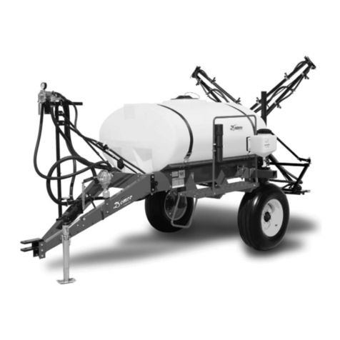
Demco RMLE User manual

AC20021, Rev 6
05/19
REAR MOUNTED SPRAYER
RMLE

Page 2 AC20021
Thank you for purchasing a Demco product. We feel you have made a wise choice and hope you are completely
satisfied with your new product. If you have any questions regarding the applications of certain solutions or chemicals,
contact your chemical supplier and follow chemical manufacturer recommendations as well as all licensing and use
restrictions or regulations.
General information................................................................................................................... 2
Safety Information .....................................................................................................................3-9
Bolt Torque................................................................................................................................. 10
Tank and Tank Skid Mounting.................................................................................................. 11
Legs, Platform, Step Mounting ................................................................................................ 12
Handrail, Manual Canister, Fresh Water Tank and ..................................................................
Boom Carrier Mounting Parts Breakdown ............................................................................. 12
Foam Marker (DFM60) Mounting Bracket Parts Breakdown and List................................. 13
RMLE Rear Mount Tank Bracket Parts Breakdown & Assembly ........................................ 14-15
Panel Mount (Strap Method) Parts Breakdown & Installation Instructions......................... 16
Polyester Bands for Demco Tanks........................................................................................... 17
DB & DFBII Boom Mounting Brackets (9416004) Parts Breakdown & List......................... 18
Ground Storage Stands for X-Fold Parts Breakdown & Assembly Instructions................. 19
Category II & Category III Parts Breakdown & List ................................................................ 20
Single Section Plumbing Kit (9470004) Parts Breakdown & List......................................... 20
3 Section Plumbing Kit (9470005) Parts Breakdown & List.................................................. 21
Sprayer Checklist....................................................................................................................... 22
GENERAL INFORMATION
1. Unless otherwise specified, high-strength (grade5)
(3 radial-line head markings) hex head bolts are used
throughout assembly of this sprayer.
2. Whenever terms “LEFT” and “RIGHT” are used in this
manual it means from a position behind sprayer and
facing forward.
3. When placing a parts order, refer to this manual for
proper part numbers and place order by PART NO.,
DESCRIPTION, and COLOR.
WARRANTY POLICY, OPERATOR MANUALS, PARTS MANUALS & REGISTRATION
Go online to www.demco-products.com to review Demco warranty policies, operator manuals and register your Demco
product.
INTRODUCTION
Chemicals are dangerous. Know exactly what you’re going to do and what is going
to happen before attempting to work with these products. Improper selection or use
can injure people, animals, plants and soil.
Always wear protective clothing such as coveralls, goggles and gloves when working
with chemicals or sprayer.
Be sure to dispose of all unused chemicals or solutions in a proper and ecologically
sound manner.
WARNING: TO AVOID PERSONAL INJURY OR PROPERTY DAMAGE, OBSERVE FOLLOWING INSTRUCTIONS:
TABLE OF CONTENTS

AC20021 Page 3
TAKE NOTE! THIS SAFETY ALERT SYMBOL FOUND THROUGHOUT THIS
MANUAL IS USED TO CALL YOUR ATTENTION TO INSTRUCTIONS INVOLVING YOUR
PERSONAL SAFETY AND SAFETY OF OTHERS. FAILURE TO FOLLOW THESE INSTRUCTIONS
CAN RESULT IN INJURY OR DEATH!
THIS SYMBOL MEANS
ATTENTION
BECOME ALERT
YOUR SAFETY IS INVOLVED!
DANGER:
Indicates an imminently hazardous situation that, if not
avoided, will result in death or serious injury. This signal
word is to be limited to most extreme situations typically
for machine components which, for functional purposes,
cannot be guarded.
WARNING:
Indicates a potentially hazardous situation that, if not
avoided, could result in death or serious injury, and includes
hazards that are exposed when guards are removed. It may
also be used to alert against unsafe practices.
CAUTION:
Indicates a potentially hazardous situation that, if not
avoided, may result in minor or moderate injury. It may also
be used to alert against unsafe practices.
If you have questions not answered in this manual, require additional copies, or if your manual is damaged, please contact
your dealer or DEMCO, 4010 320th Street, Boyden, IA 51234
ph: (712) 725-2311 or Toll Free: 1-800-543-3626 Fax: (712) 725-2380 or 1-800-845-6420
http://www.demco-products.com
SIGNAL WORDS:
This manual uses the following signal words--DANGER,
WARNING, and CAUTION-- with safety messages. The
appropriate signal word has been selected using the
following guidelines.
SAFETY

Page 4 AC20021
Every year many accidents occur which could have been avoided by a few seconds of thought and a more
careful approach to handling equipment. You, the operator, can avoid many accidents by observing the
following precautions in this section. To avoid personal injury, study the following precautions and insist
those working with you, or you yourself, follow them.
In order to provide a better view, certain illustrations in this manual may show an assembly with a safety
shield removed. However, equipment should never be operated in this condition. Keep all shields in place.
If shield removal becomes necessary for repairs, replace shield prior to use.
Replace any caution, warning, danger or instruction safety decal that is not readable or is missing. Location
of such decals is indicated in this booklet.
Do not attempt to operate this sprayer under the influence of alcohol or drugs.
Review safety instructions with all users.
Operator should be a responsible adult. DO NOT ALLOW PERSONS TO OPERATE OR ASSEMBLE THIS
UNIT UNTIL THEY HAVE DEVELOPED A THOROUGH UNDERSTANDING OF SAFETY PRECAUTIONS
AND HOW IT WORKS.
To prevent injury or death, use a tractor equipped with a roll over protective system (ROPS). Do not paint
over, remove, or deface any safety signs or warning decals on your sprayer. Observe all safety signs and
practice instructions on them.
Never exceed limits of a piece of machinery. If its ability to do a job, or to do so safely is in question-DON’T
TRY IT.
It is the responsibility of customer to know lighting and marking requirements of local highway authori-
ties and to install and maintain sprayer to provide compliance with regulations. Add extra lights when
transporting at night or during periods of limited visibility.
SAFETY...YOU CAN LIVE WITH IT
SAFETY
EQUIPMENT SAFETY GUIDELINES
LIGHTING AND MARKING

AC20021 Page 5
Types of safety sign and locations on equipment are shown in illustration below. Good safety requires that
you familiarize yourself with various safety signs, type of warning, and area or particular function related
to that area, that requires your SAFETY AWARENESS.
AB21002
AB21001
AA21014
AB21014
WARNING
To prevent serious injury or
death.
Do not ride or stand on sprayer
while any part of sprayer is
moving.
Keep riders off at all times.
REV 1 AB21001
WARNING
T o prevent serious injury or death
• Refer to che mica l supp lier and manufacturer r ecom mend ations and all
l icensing re strictions or reg ulations.
• Always wear recommended protecti ve clo thing when worki ng with chemicals o r
sprayer.
• Dis pose of all unu sed chemica ls or solutions in pr oper and ecol ogically
sou nd manner. Imprope r use can injur e peop le, animals , plants and so il.
REV 1AB21014
AB21001 AB21014
CLEAR
FRESH
WATER
ONLY
AA21014
AA21014
WARNING
REV 1 AB21002
To prevent serious injury or death
•Store sprayer on hard level surface.
•Store empty.
AB21002
SAFETY SIGN LOCATIONS
SAFETY

Page 6 AC20021
• Keepsafetysignscleanandlegibleatalltimes.
• Replacesafetysignsthataremissingorhavebecomeillegible.
• Replacementpartsthatdisplayedasafetysignshouldalsodisplaycurrentsign.
• Safetysignsareavailablefromyourdistributor,dealerpartsdepartment,orfactory.
How to install safety signs:
• Besurethatinstallationareaiscleananddry.
• Decideonexactpositionbeforeyouremovebackingpaper.
• Removesmallestportionofsplitbackingpaper.
• Aligndecaloverspeciedareaandcarefullypresssmallportionwith
exposed sticky backing in place.
• Slowlypeelbackremainingpaperandcarefullysmoothdecalintoplace.
• Airpocketscanbepiercedwithapinandsmoothedoutusingpieceofbackingpaper.
• Carefullystudyandunderstandthismanual.
• Donotwearloose-ttingclothingwhichmaycatchinmovingparts.
• Alwayswearprotectiveclothingandsubstantialshoes.
• Itisrecommendedthatsuitableprotectivehearingandeyeprotectionbeworn.
• Theoperatormaycomeincontactwithcertainmaterialswhichmayrequirespecicsafety
equipment relative to handling of such materials. (Examples: extremely dusty, molds,
fungus, bulk fertilizers, etc.)
• Givesprayeravisualinspectionforanyloosebolts,wornparts,orcrackedwelds,andmake
necessary repairs. Follow maintenance safety instructions included in this manual.
• Besuretherearenotoolslyingonorinequipment
• Donotusesprayeruntilyouaresurethatareaisclear,especiallyaroundchildrenand
animals.
• Don’thurrylearningprocessortakesprayerforgranted.Easeintoitandbecomefamiliar
with your new equipment.
• Practiceoperationofyourequipmentanditsattachments.Completelyfamiliarizeyourself
and other operators with its operation before using.
• UseatractorequippedwithRollOverProtectionSystem(ROPS)andfastenyourseatbelt
prior to starting engine.
• ManufacturerdoesnotrecommendusageofatractorwithROPSremoved.
SAFETY SIGN CARE
BEFORE OPERATION:
SAFETY

AC20021 Page 7
• Movetractorwheelstowidestrecommendedsettingstoincreasestability.
• Donotallowanyonetostandbetweentongueorhitchandtowingvehiclewhenbackinguptosprayer.
• Bewareofbystanders,PARTICULARLY CHILDREN! Always look around to make sure that it is safe to start
engine of towing vehicle or move sprayer. This is particularly important with higher noise levels and quiet cabs,
as you may not hear people shouting.
• NOPASSENGERSALLOWED- Do not carry passengers anywhere on or in the tractor or sprayer.
• Keephandsandclothingclearofmovingparts.
• Donotclean,lubricate,oradjustyoursprayerwhileitismoving.
• Whenhaltingoperation,evenperiodically,settractorortowingvehiclesbrakes,disengagePTO,shutoffengine,
and remove ignition key.
• Beespeciallyobservantofoperatingareaandterrain-watchforholes,rocks,orotherhiddenhazards.Always
inspect area prior to operation.
- DO NOT operate near edge of drop-offs or banks.
- DO NOT operate on steep slopes as overturn may result.
- Operate up and down (not across) intermediate slopes. Avoid sudden starts and stops.
• Pickthemostlevelpossibleroutewhentransportingacrosselds.Avoidedgesofditches,gullies,andsteep
hillsides.
• Beextracarefulwhenworkingoninclines.
• Periodicallyclearsprayerofbrush,twigs,orothermaterialstopreventbuildupofdrycombustiblematerials.
• Maneuvertractorortowingvehicleatsafespeeds.
• Avoidoverheadwires.Contactwithoverheadlinescouldcauseseriousinjuryordeath.
• Avoidloosegravel,rocks,andholes;theycanbedangerousforsprayeroperationormovement.
• Allowforunitlengthwhenmakingturns.
• Donotwalkorworkunderraisedcomponentsorattachmentsunlesssecurelysupported.
• Keepallbystanders,pets,andlivestockclearofworkarea.
• Neverstandalongsideofunitwithenginerunningorattempttostartengineand/oroperatemachinewhile
standing alongside of unit.
• Neverleaverunningequipmentattachmentsunattended.
• Asaprecaution,alwaysrecheckhardwareonequipmentfollowingevery100hoursofoperation.Correctall
problems. Follow maintenance safety procedures.
DURING OPERATION
SAFETY

Page 8 AC20021
• Followingoperation,orwhenunhitching,stoptractorortowingvehicle,setbrakes,disengagePTOandallpower
drives, shut off engine and remove ignition key.
• Storeunitinanareaawayfromhumanactivity.
• Donotparkequipmentwhereitwillbeexposedtolivestockforlongperiodsoftime.Damageandlivestock
injury could result.
• Donotpermitchildrentoplayonoraroundstoredunit.
• Makesureallparkedmachinesareonahard,levelsurfaceandengageallsafetydevices.
• Adoptsafedrivingpractices:
- Keep brake pedals latched together at all times. NEVER USE INDEPENDENT BRAKING WITH MACHINE IN
TOW, LOSS OF CONTROL AND/OR UPSET OF UNIT CAN RESULT.
- Always drive at a safe speed relative to local conditions and ensure that your speed is low enough for an emer-
gency stop. Keep speed to a minimum.
- Reduce speed prior to turns to avoid risk of overturning.
- Always keep tractor or towing vehicle in gear to provide engine braking when going
downhill. Do not coast.
- Do not drink and drive!
• Complywithstateandlocallawsgoverninghighwaysafetyandmovementoffarmmachinery.
• Useapprovedaccessorylightingagsandnecessarywarningdevicestoprotectoperatorsofothervehicleson
highway during transport. Various safety lights and devices are available from your dealer.
• Useofashingamberlightsisacceptableinmostlocalities.However,somelocalitiesprohibittheiruse.Local
laws should be checked for all highway lighting and marking requirements.
• Whendrivingatractorandsprayerunder20mph(40kph)dayornight,useashingamberwarninglightsand
a slow moving vehicle (SMV) identification emblem.
• Planyourroutetoavoidheavytrafc.
• Beasafeandcourteousdriver.Alwaysyieldtooncomingtrafcinallsituations,including
narrow bridges, intersections, etc.
• Beobservantofbridgeloadingratings.Donotcrossbridgesratedlowerthangrossweightatwhichyouare
operating.
• Watchforobstructionsoverheadandsidetosidewhiletransporting.
• Alwaysoperateequipmentinapositiontoprovidemaximumvisibilityatalltimes.Makeallowancesforincreased
length and weight of sprayer when making turns, stopping, etc.
• SAFETYCHAINS:If equipment is going to be transported on a public highway, Always follow state and
local regulations regarding safety chains and auxiliary lighting. Be sure to check with local law enforcement
agencies for your own particular regulations. If required safety chains should be obtained and installed. Only
safety chains (not elastic or nylon/plastic tow straps) should be used to retain connection between towing
and towed machines in event of separation of primary attaching system. Use a high strength, appropriately
sized hitch pin with a mechanical retainer and attach safety chains. Criss cross chains under tongue and se-
cure to draw bar cage, mounting loops, or bumper frame.
SAFETY
HIGHWAY AND TRANSPORT OPERATIONS
PERFORMING MAINTENANCE

AC20021 Page 9
Your best assurance against accidents is a careful and responsible operator. If there is any portion of this
manual or function you do not understand, contact your local authorized dealer or manufacturer.
• Goodmaintenanceisyourresponsibility.Poormaintenanceisaninvitationtotrouble.
• Makesurethereisplentyofventilation.Neveroperateengineoftowingvehicleinaclosedbuilding.Exhaust
fumes may cause asphyxiation.
• Beforeworkingonthismachine,stoptowingvehicle,setbrakes,disengagePTOandallpowerdrives,shutoff
engine and remove ignition key.
• Becertainallmovingpartsandattachmentshavecometoacompletestopbefore
attempting to perform maintenance.
• Always use a safety support and block wheels. Never use a jack to support machine.
• Alwaysusepropertoolsorequipmentforjobathand.
• Useextremecautionwhenmakingadjustments.
• Followtorquechartonpage10inthismanualwhentighteningboltsandnuts.
• Neveruse yourhandsto locatea hydraulicleakonattachments. Usea smallpiece ofcardboardor wood.
Hydraulic fluid escaping under pressure can penetrate skin.
• Openingsinskinandminorcutsaresusceptibletoinfectionfromhydraulicuid.
Without immediate medical treatment, serious infection and reactions can occur.
• Whendisconnectinghydrauliclines,shutoffhydraulicsupplyandrelieveallhydraulicpressure.
• Replaceall shields and guards after servicing and before moving.
• Afterservicing,besurealltools,partsandserviceequipmentareremoved.
• Donotallowgreaseoroiltobuilduponanysteporplatform.
• Whenreplacingboltsrefertoownersmanual.
• Refertobolttorquechartonpage12forheadidenticationmarking.
• Wherereplacementpartsarenecessaryforperiodicmaintenanceandservicing,genuinefactoryreplacement
parts must be used to restore your equipment to original specifications. Manufacturer will not claim responsibility
for use of unapproved parts or accessories and other damages as a result of their use.
• Ifequipmenthasbeenalteredinanywayfromoriginaldesign,manufacturerdoesnotacceptanyliabilityfor
injury or warranty.
• Areextinguisherandrstaidkitshouldbekeptreadilyaccessiblewhileperformingmaintenanceonthis
sprayer.
PERFORMING MAINTENANCE
REMEMBER
SAFETY

Page 10 AC20021
Torque figures indicated are valid for non-greased or non-oiled threads and heads unless otherwise specified. Therefore, do not grease or oil
bolts or capscrews unless otherwise specified in this manual. When using locking elements, increase torque values by 5%.
* GRADE or CLASS value for bolts and capscrews are identified by their head markings.
BOLT TORQUE DATA FOR STANDARD NUTS, BOLTS, AND CAPSCREWS.
Tighten all bolts to torques specified in chart unless otherwise noted. Check tightness of bolts periodically, using bolt chart as guide.
Replace hardware with same grade bolt.
NOTE: Unless otherwise specified, high-strength Grade 5 hex bolts are used throughout assembly of equipment.
TORQUE SPECIFICATION
*5$'(
&/$66
&/$66
*5$'( *5$'(
&/$66
$
Bolt Torque for Standard bolts *
“A” GRADE 2 GRADE 5 GRADE 8
lb-ft (N.m) lb-ft (N.m) lb-ft (N.m)
1/4” 6 (8) 9 (12) 12 (16)
5/16” 10 (13) 18 (25) 25 (35)
3/8” 20 (27) 30 (40) 45 (60)
7/16” 30 (40) 50 (70) 80 (110)
1/2” 45 (60) 75 (100) 115 (155)
9/16” 70 (95) 115 (155) 165 (220)
5/8” 95 (130) 150 (200) 225 (300)
3/4” 165 (225) 290 (390) 400 (540)
7/8” 170 (230) 420 (570) 650 (880)
1” 225 (300) 630 (850) 970 (1310)
Bolt Torque for Metric bolts *
“A” CLASS 8.8 CLASS 9.8 CLASS 10.9
lb-ft (N.m) lb-ft (N.m) lb-ft (N.m)
6 9 (13) 10 (14) 13 (17)
7 15 (21) 18 (24) 21 (29)
8 23 (31) 25 (34) 31 (42)
10 45 (61) 50 (68) 61 (83)
12 78 (106) 88 (118) 106 (144)
14 125 (169) 140 (189) 170 (230)
16 194 (263) 216 (293) 263 (357)
18 268 (363) -- -- 364 (493)
20 378 (513) -- -- 515 (689)
22 516 (699) -- -- 702 (952)
24 654 (886) -- -- 890 (1206)
BOLT TORQUE

AC20021 Page 11
1. Begin by fastening the tank skid (#1) to the
mainframe (#3) using 1/2” x 1-1/4” hex head bolts
(#2), 1/2”flatwashers (#4), and 1/2” locknuts (#5).
2. Fasten mounting plates (#10), and strap anchors
(#11) to tank strap (#7) using 5/16” x 3/4” bolts
(#12), and 5/16” locknuts (#15). Refer to page 2
for strap and strap anchor routing.
3. Place tank (#6) onto the tank skid (#1). Using tank
straps (#7) fasten tank to skid with 3/8” x 6” hex
head bolts (#18), and 3/8” locknuts (#9).
4. Fasten panel mount stem (#13) to the
mounting plates (#10) using 5/16” sq. u-bolts (#14),
and 5/16” locknuts (#15). Used when 3 section
boom control is ordered.
5. Fasten panel mount plate (#16) to panel
mount stem (#13) using 5/16” x 1” hex head
bolts (#17), and 5/16” locknuts (#15).
6. Mount the control panel (#19) to the
mounting plate (#16) using bolts included with
control panel mounting package. REFER TO
CONTROL PANEL MANUAL FOR PARTS
BREAKDOWN AND INSTRUCTIONS.
NOTE: Do not let any agricultural chemical stand in the
applicator tank when not in use. Chemicals left
standingin equipmentthat isnotin use,shorten
the life of the tanks, pumps, hoses, etc. The
longer the chemical stands, the more water
evaporates and the stronger the chemical
solution becomes.
3
6
1
2
4
5
9
7
18
10
13
16
17
15
14
14
11
15
12
19
7
ASSEMBLY
15
10
INSTALLATION
TANK AND TANK SKID MOUNTING

Page 12 AC20021
HANDRAIL, MANUAL HOLDER,
FRESH WATER TANK
AND BOOM CARRIER
PARTS LIST
Please order replacement parts by PART NO. and DESCRIPTION
ASSEMBLY
1. Fasten boom carrier (#1) to the sprayer frame using
3/8” x 2-1/2” square u-bolts (#2), and 3/8” locknuts (#3).
2. Fasten handrail (#4) to the platform mounting brackets
using 1/4” x 1” square u-bolts (#5), and 1/4” locknuts (#6).
3. Fasten canister bracket (#9) to the handrail (#4) using two 1”
hose clamps (#10). Attach the manual canister (#11) to the
canister bracket(#9).
4. Fasten fresh water tank bracket (#7) to the handrail tube
(#4), using 1/4” x 1” square u-bolts (#5),
1/4” flatwasher (#8), and 1/4” locknuts (#6).
12
2
3
3
3
2
2
1. 03644-10 1 Boom Carrier
2. 01887 4 3/8”-16 UNC x 2-1/2” x 3-1/2” Sq. U-bolt
3. 02592 8 3/8”-16 UNC Nylon Insert Locknut
4
5
5
6
5
5
7
86
1
2
3
3
3
1
4
65
5
*7
8
10
6
11
12
13
9
9
14
8
8
4
4
4
3
8
1. Fasten the left and right platform mounts
(#15 & 17) to the mainframe (#16) using eight
1/2” x 1-1/4” Hex head bolts, and eight 1/2” locknuts.
2. Attach the front legs (#1) to the mainframe using
1/2” x 3-1/2” hex head bolts (#3) and 1/2” Locknuts
(#4). Lock legs in lowered position using pin (#5)
and hairpin (#6).
3. Attach the rear legs (#2) to the right and left
platform mounts using 1/2” x 3-1/2” hex head bolts
(#3) and 1/2” Locknuts (#4). Lock legs in lowered
position using pin (#5) and hairpin (#6).
15
17
16
6
5
4. Attach platform brackets (#9) to the mainframe using
1/2” x 1-1/4” hex head bolts (#8) and 1/2” locknuts
(#4).
NOTE: Extension brackets (*#7) are used on RMLE
units only.
5. Fasten platform (#10) to the platform brackets (#9)
using 3/8” x 1-1/4” hex head bolts (#11), 3/8”
flatwashers, and 3/8” locknuts (#13).
6. Attach step (#14) to the platform (#10) using 1/2” x
1-1/4” hex head bolts (#8), and 1/2” locknuts (#4).
4
4
10
911
LEGS, PLATFORM AND STEP
MOUNTING
INSTALLATION

AC20021 Page 13
RML
6.00”
2
2
2
1
3
3
3
REF. PART
NO. NO. QTY. DESCRIPTION
PARTS LIST
Please order replacement parts by PART NO. and DESCRIPTION.
ASSEMBLY
1
1. Begin by bolting on the Extension Bracket
(#1) using six 1/2” x 1-1/4” hex head bolts (#3)
and nylon insert locknuts (#4).
2. Continue assembly with step 1 of DFM60
Foam Marker owners manual.
1. 03746-10 2 Extension Bracket
2. 00967 6 1/2” x 1-1/4” Hex Head Bolts (Gr.5)
3. 02178 6 1/2” Nylon Insert Locknut
4. 00085 2 1/2” Flat Washer
4
INSTALLATION
OPTIONAL REAR MOUNT EXTENSION BRACKET FOR FOAM MARKER (DFM 60)

Page 14 AC20021
16
18
17
21
19
20
7
7
40
39 38
2
18
2
1
4
3
*6
5
7
1
2
3
3
3
3
4
5
11
12
13
14
15
3
310
7
18
3
37
2
5
4
83
9
10
3
7
3
7
20
3
7
15
32
24
*23
26
26
27
29
28
28
30
31
*22
33
*34
*34
25
31
35
24
31
37
PARTS BREAKDOWN

AC20021 Page 15
REF. PART
NO. NO. QTY. DESCRIPTION
Please order replacement parts by PART NO. and DESCRIPTION.
**Straps are sold per foot. See Page 19 for proper strap length.
1. 05387-10 2 Front Legs
2. 01897 4 1/2”-13 UNC x 3-1/2” Hex Hd. Bolt Gr.5
3. 02178 20 1/2”-13 UNC Nylon Insert Locknut
4. 01718-95 4 Pin
5. 00182 4 Hairpin
6. 05381-10 1 Mainframe (RMLE)
7. 00967 16 1/2”-13 UNC x 1-1/4” Hex Head Bolt Gr.5
8. 05396-10 1 Right Platform Mount
9. 05386-10 1 Left Platform Mount
10. 05388-10 2 Rear Leg
11. 07744-10 2 Platform Mounting Bracket
12. 07745-10 1 Platform Step
13. 00523 4 3/8”-16 UNC x 1-1/4” Hex Head Bolt Gr.5
14. 00059 4 3/8” Flatwasher
15. 02178 4 3/8”-16 UNC Nylon Insert Locknut
16. 00164-10 1 Step
17. 07746-10 1 Hand Rail
18. 04822 4 1/4”-20 UNC x 1” x 1-1/2” Sq. U-bolt
19. 00214 4 1/4” Flatwasher
20. 02772 18 1/4”-20 UNC Nylon Insert Locknut
21. 05615-30 1 Freshwater Tank Bracket
22. 02882-10 1 Tank Skid (400 gal. Elliptical (RMLE)
- 02130-10 1 Tank Skid (500 gal. Elliptical (RMLE)
23. PE400 RA 1 400 gal. Elliptical Tank (RMLE)
- PE500 RA 1 500 gal. Elliptical Tank (RMLE)
24. **03728 2 4” Tank Strap
25. 05784-95 6 Large Strap Anchor (4”)
26. 03712-10 2 Mounting Bracket for Elliptical Tank Panel Stem
27. 05391-10 1 Panel Mount Stem
28. 00909 2 5/16”-18 UNC x 1-1/4” Sq. U-bolt
29. 04936-30 1 Panel Mount Plate (included with plumbing kit)
30. 02990 4 5/16”-18 UNC x 1” Hex Head Bolt (not included)
31. 02802 8 5/16”-18 UNC Nylon Insert Locknut
32. 02157 8 3/8”-16 UNC x 6” Full Thread Hex Head Bolt Gr.5
33. 00085 4 1/2” Flatwasher
34. 03746-10 2 Platform Extension Bracket (used on RMLE only)
35. 01263 4 5/16”-18 UNC x 3/4” Hex Head Bolt
37. 00004 4 5/16 Flat Washer
38. 10241 1 Owners Manual Canister
39. 10242 1 Canister Bracket
40. B16H 2 1” Hose Clamp
-- AB21002 1 Replacement Warning Store Empty Decal
-- AB21001 1 Replacement Warning Do Not Ride or Stand Decal
-- AA21027 2 Replacement “Demco” Decal
-- AA21014 1 Replacement Fresh Water Decal
-- AB21014 1 Replacement Warning Wear Protective Clothing Decal
-- AA21002 2 Replacement “Boyden, Iowa” Decal
RMLE PARTS LIST

Page 16 AC20021
Thursday, March 03, 2005 11:45:45
REF. PART
NO. NO. QTY. DESCRIPTION
Please order replacement parts by PART NO. and DESCRIPTION.
VIEW A
18-1/2”
For
Round
Tanks
Approx.
1. Locate the center of the strap (#1) by folding
it in half. Mark the strap approximately, 11”
for elliptical tanks and 9-1/4” for round tanks,
fromboth sides of center. Thisis wherethe 90°
bend angle of the anchors (#2) will be located.
Weave strap throughone anchor usingmethod
shown in , note the direction of the anchors,
and mount the other anchor as shown in .
2. Place strap and anchors over band area on
tank. Locate the anchor shown in towards
the side of the tank where the panel will be
mounted. Install anchors on the strap ends
as shown on opposite side of this sheet.
3. Attach the panel mounts (#6) to the anchors
(#2) using four 5/16” x 3/4” bolts (#4) and
locknuts (#5), as shown. Attach the panel
mount stem to strap mounts (#6) using two
5/16” x 1-1/4” square u-bolts (#3) and
locknuts.
INSTALLATION
1
2
3
6
5
4
Panel Mount Stem
3
3
5
6
2
5
1
1
2
3
4
5
5
6
1. - 2 Polyester Strap
05367 - 1-3/4”-Black Strap
03728 - 4”-Black Strap
2. - 2 Strap Anchor
05785-95 2 Small Strap Anchor (1-3/4”)
05784-95 2 Large Strap Anchor (4”)
3. 00909 2 5/16”-18 UNC x1-1/4” Square U-bolt
4. 01263 4 5/16”-18 UNC x 3/4” Hex Head Bolt
5. 02802 8 5/16”-18 UNC Nylon Insert Locknut
6. 03712-10 2 Mounting Plate for Elliptical Tank
- 03713-10 2 Mounting Plate for Round Tank
4
22”
For
Elliptical
Tanks
PANEL MOUNT (STRAP METHOD) PARTS BREAKDOWN & INSTALLATION

AC20021 Page 17
*Strap only sold by the Linear Foot
Locate tank, locate inches of material needed per band, multiply that
length by the number of bands needed
divide by 12 = number of linear feet needed
REF. PART
NO. NO. QTY. DESCRIPTION
Attaching Hardware for Strap Bands
NOTE: Be sure to center the straps and make final adjustments before
tightening them down with the bolts.
NOTE: Be sure to check the straps periodically to ensure they are
tight.
VIEW A
To replace the old style
steel tank bands with new
polyester straps, remove
the steel bands and use the
bolts that secured them to
attach the new straps.
Weave the straps (#1)
through the Strap Anchors
(#2) as shown in *Allow a
minimum of 2” overlap past
the anchor on the tank side
of strap.
INSTALLATION
*
1
2
3
Please order replacement parts by PART NO. and DESCRIPTION.
Please order replacement polyester strap material by PART NO., DESCRIPTION and by the LINEAR FOOT.
Specify the tank to be fit and material will be cut to length before shipment.
1. - 2 Polyester Strap
05367 - 1-3/4”-Black Strap (Sold per foot)
03728 - 4”-Black Strap (Sold per foot)
2. - 2 Strap Anchor
05785-95 2 Small Strap Anchor (1-3/4”)
05784-95 2 Large Strap Anchor (4”)
3. 04352 2 5/16”-18 UNC x 4” Full Thread Bolt
- 02802 2 5/16”-18 UNC Nylon Insert Locknut
3. 01885 2 3/8”-16 UNC x 5” Full Thread Bolt
3. 02157 2 3/8”-16 UNC x 6” Full Thread Bolt
- 02592 2 3/8”-16 UNC Nylon Insert Locknut
INCHES USED
PER BAND
LENGTH
STRAP
WIDTH COLOR PART NO. TANKS
1-3/4” Black *05367 50” Planter Tanks P25 23, P55 23, P85 24, P110 24
64” Planter Tanks P110 30, P150 30
56” 150-250 gallon Cutaway tanks (Short side one per tank)
74” 150-250 gallon Cutaway tanks (Tall side one per tank)
60” 200 gallon P200 32
86” 200 gallon elliptical PE200R
50” Lawn & Garden Line tanks P55 23, P85 24
64” 110, 150 gallon Rear Mount tanks P110 30, P150 30
86” 300 gallon PE300R, P300 38
4” Black *03728 82” 400 & 500 gallon P400 42, P500 42 and S42 (saddle)
112” 400 & 500 gallon PE400R, PE500R, 750 gallon PE750DA
94” 500 & 600 gallon PE500A, PE600A & S48, PS548A (saddles)
108” TMC 500 gallon SKD”48”
126” 750 gallon PE750A, 1000 gallon PE1000DA
130” 1000 & 1600 gallon elliptical tank P1000A and PS-1016E (skid)
126” 60” dia. round tanks SKD”60” (skid)
150” 72” dia. round tanks SKD”72” (skid)
POLYESTER BANDS FOR DEMCO TANKS

Page 18 AC20021
REF. PART
NO. NO. QTY. DESCRIPTION
DB AND DFBII GROUND STAND PARTS LIST
Please order replacement parts by PART NO. and DESCRIPTION.
1. 07650-30 2 Ground Stand Receiver Tube
2. 07651-30 2 Ground Stand Insert Tube
3. 07735-30 2 Adjustable Leg
4. 07653-30 4 Back-up Plate
5. 00059 16 3/8”Flat Washer
6. 00182 4 Hair pin
7. 01404-95 2 Locking Handle
8. 01718-95 4 Locking Pin
9. 02592 12 3/8” Nylon Insert Locknut
10. 02769 8 3/8” x 4” Hex Head Bolt(Gr.5)
2
3
4
1
7
6
9
9
7
1
2
3
6
4
4
4
5
5
8
8
10
10
10
DB AND DFBII BOOM MOUNTING BRACKET KIT (9416004)

AC20021 Page 19
9488011 PARTS LIST
1. 07650-30 2 Rear Leg Receiver Tube
2. 05583 4 3/8”-16 UNC x 2-1/8” x 4-7/8” Square U-bolt
3. 00059 8 3/8” Flatwasher
4. 02592 12 3/8”-16 UNC Nylon Insert Locknut
5. 07651-30 2 Rear Insert Tube
6. 01404-95 2 Locking Bolt
7. 07735-30 4 Adjustable Leg
8. 01718-95 4 Lock Pin
9. 00182 4 .125 Hair Pin
Please order replacement parts by PART NO. and DESCRIPTION.
STORAGE STANDS ASSEMBLY INSTRUCTIONS
The Flotation Boom Mount and 3-Point Mount
must be assembled before proceeding.
1.Mount the Rear Leg ReceiverTube (#1) to the bottom of the
Center Tube Assembly using two 3/8” Square U-Bolts (#2),
four 3/8” Flatwashers (#3) and four 3/8” Locknuts (#4).
2. Insert the Rear Insert Tube (#5) and secure using a 3/8”
Locking Bolt (#6)
3. Insert the Adjustable Legs (#7) and secure using a Locking
Pin (#8) and Hair Pin (#9)
Repeat on other side.
1
2
3
4
7
6
5
1
2
3
4
6
9
8
7
5
9
8
GROUND STORAGE STANDS FOR X-FOLD MOUNTING

Page 20 AC20021
2
3
31
4
2
1
44
25
4
4
4
REF. PART
NO. NO. QTY. DESCRIPTION
Please order replacement parts by PART NO. and DESCRIPTION.
1. 05382-95 2 1-1/8” x 7-3/4” Pin
2. 00328-95 4
1-7/16 “O.D x 1-3/16” I.D x 3” lg.
Bushing
3. 00332-95 1 1” Dia. x 4” Pin
4. 00006 6 3/16” Hairpin
REF. PART
NO. NO. QTY. DESCRIPTION
CATEGORY II HITCH MODEL RMSE PARTS LIST
Please order replacement parts by PART NO. and DESCRIPTION.
1. 05382-95 2 1-1/8” x 7-3/4” Pin
2. 00328-95 4
1-7/16 “O.D x 1-3/16” I.D x 3” lg.
Bushing
3. 00332-95 1 1” Dia. x 4” Pin
4. 00006 6 3/16” Hairpin
5. 05383-95 1 1-1/4” O.D x 1” I.D x 1-15/16” Bushing
44
CATEGORY III HITCH MODEL RMLE PARTS LIST
Please order replacement parts by PART NO. and DESCRIPTION.
8. B12H 8 3/4” SS Gear Clamp
9. 340RB - 3/4” I.D. Rubber Hose
10. T34 1 3/4” Tee
11. BEL1034 1 1” MPT x 3/4” Hose Barb Elbow Fitting (GFP)
12. BEL114 3 1-1/4” MPT x 1-1/4” Hose Barb Elbow Fitting(GFP)
13. B24H 10 1-1/4” SS Gear Clamp
14. 1140RB - 1-1/4” I.D. Rubber Hose
15. BA114 4 1-1/4” MPT x 1-1/4” Hose Barb Fitting (GFP)
16. UV125FP 2 1-1/4” Nylon Ball Valve
Tank
See Control Panel Own-
ers Manual for Hook-Up
& Operation
Centrifugal
Pump
Plumbing Kit for Front/Rear Mounts
9470004 - Single Section Control
1
2
3
3
5
7
8
8
9
9
9
10
11 14
13
13
13
13 12
15
15
16 14
87
88
9
8
1
2
3
3
3
6
15
Electric
Control
Manual
Control
2
REF. PART
NO. NO. QTY. DESCRIPTION
PLUMBING PARTS LISTS
- D3371PA 2 Agitation Assembly
1. *5044 1 2 Jet Agitation Wand Assembly
2. *R1212 1 Jet Agitation Tee Fitting
3. *P012DA 1 Jet Agitation Fitting
6. P114AV 1 1-1/4” Anti-Vortex Tank Outlet Assembly
7. BEL1234 2 1/2” MPT x 3/4” Elbow Fitting (GFP)
*These items sold as complete part only (D3371P).
TOW AND THREE POINT HITCH INSTRUCTIONS
Table of contents
Other Demco Paint Sprayer manuals
Popular Paint Sprayer manuals by other brands

HERO
HERO B series operating & maintenance manual

oneConcept
oneConcept 10029203 manual

EUROPRO
EUROPRO Mini-Sandblaster 10L user manual

Greenleaf
Greenleaf Workhorse UTV425HM Assembly / operation instructions / parts

Central Pneumatic
Central Pneumatic 96382 Assembly and operation instructions

Central Pneumatic
Central Pneumatic 93506 Assembly and operating instructions