demi L23HP User manual

/Built/L23HP.doc 1 12/27/2017
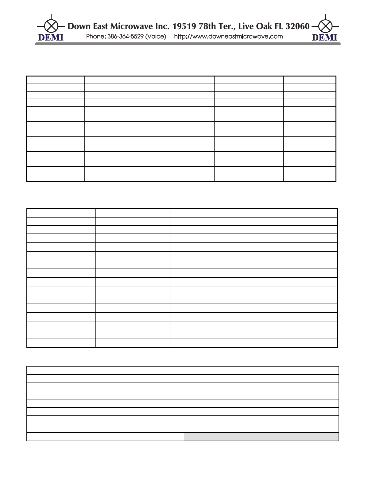
DEM Part Number L23HP SN__________
1296 MHz Transverter Set For_____________________
Power Out Maximum:
25 W linear
Noise Figure and Gain:
1.5 dB maximum @ 17 dB conversion gain
DC Power Requirement:
11.5 - 15.5 VDC @ 10 Amp
IF Option:
Common Split
Max IF Drive Level
< 0dBm +10dBm 100 mW 1W 10W
10 MHz Source Level
+3dBm +/- 6dB (Always terminate the port when not in use)
Antenna Option:
Common Separate TX & RX
Transmit Enable: Pin 5
Ground Positive Voltage
Other Options: Pin 4
Pin 9
Sequencer Enabled Disabled
Sequencer Outputs Transmit Receive
Pin 1 (Sequencer step 1) Open High (750ma)
Pin 2 (Sequencer step 2) High (750ma) Open
Pin 3 (Sequencer step 3) Low (100ma) Open
Pin 6 Ground Ground Ground
Pin 7 Ground Ground Ground
Pin 8 Ground Ground Ground
Other notes:
Operational Overview: This is the
newest version of Down East Microwave’s
23 cm Transverter. It is a complete new
design in a smaller package utilizing the
latest in MMIC amplifier and SAW filter
technology coupled with a standard low
phase noise synthesizer for frequency
accuracy and stability. This technology
allows a “No-Tune” performance and
function enabling the user to select a
different IF frequency range (10, 6, or 2
Meters) if desired. This design also
includes other improvements over past
versions by offering a 4 step sequencer, a

/Built/L23HP.doc 2 12/27/2017
25 watt output power level with additional options such as a mast mount preamplifier control and a
remote DC power control.
What is the same as the past is the RF and IF configurations and drive level options. The
transverter may be configured with common or split IF at any drive level between -20dBm to 10
Watts. This can be changed easily at any time by the user. All IF connections are made through
standard BNC connectors. The RF configurations are separate TX and RX ports or a common RF.
An onboard relay is standard and may be reconfigured at any time. The RF ports are type N
connectors only. Keying the transverter is done by either a voltage (PTT-H) or a ground on
transmit (PTT-L) through the AUX connector which also contains the Sequencer outputs and
additional any requested additional options. The DC cabling and AUX connections are supplied.
Configuration Overview:
The DEM L23HP transverter is designed to interface to all modern
amateur radio transceivers but has been specifically configured to your transceiver’s specifications.
As indicated on the front page, some user options and configurations need to be selected before
delivery but may be user changeable. Let’s review your configuration and verify that your interface
will be easy and trouble free. Please refer to the front page chart for the following.
DEMI Part Number Verification:
IMPORTANT: The transverters operating bandwidth is restricted by first your IF frequency
bandwidth and secondly, by the Band Pass filters utilized in the design. The usable RF bandwidth
is approximately 1280-1300 MHz
All DEMI transverters contain the operating band within the part
number, i.e., L23HP equates to the 23 centimeter band. (1260-1300 MHz) Since this is the first
transverter design that has a user selectable IF frequency, we simply indicate what the transverter
is “Set For” under the Serial Number on the front page. The configured IF frequency is what we
have on record as your request. If this is incorrect or your desires have changed, it is not a problem
and will be discussed in a section of this manual entitled “If Frequency Selection”.
RF Output :
Next is the maximum linear output power level of the transverter that should not be
exceeded if linear operation is expected. The “Other Notes” section will indicate if a custom
output level was selected. In most cases, the transverter is capable of higher output power but is
not recommended because of excessive “on the air” distortion products.
Noise Figure and Gain:
The noise figure and gain listed are the minimum requirements. All
transverters meet or exceed these specifications. Utilizing the latest PHEMPT and SAW filter
technology, we have designed a receiver chain for gain management, IMD performance, and noise
figure to eliminate over load and out of band interference maintaining a stable, quiet, sensitive
receiver. Please note. The noise figure of the transverter is always better through a separate RX
connector and not through the Common Antenna connection.
DC Power Requirement:
Always choose the correct level of fusing for protection.
The DC power requirement is listed and should be used as a guideline.
Please include some “Buffer” in your power supply to eliminate voltage drop delivered to the
Transverter. If a custom lower power is requested, a lower current power supply may be utilized.
IF Option: The IF option has two choices. A “Common”IF connector in which both TX and RX
IF frequencies are conducted through a single connector, or “Split”
IF connections with a separate
connector for the receive and transmit connections to your transceiver.

/Built/L23HP.doc 3 12/27/2017
Maximum IF Drive:The maximum IF drive level is specified. This may be applied to the Common
port or the separate TXIF port. You may have specified a specific IF drive level and it will fall into
one of the 5 ranges listed. The transverter will produce full power at your desired drive level but
adjustment of the TXIF control will be necessary. This will be covered in the “Set-Up”
section.
Antenna Option:
The RF output option is either a single port (Common RF) for both TX and RX
or there will be two separate ports, one RX and one TX. For the common port, a PC board RF
relay is utilized that allows the output configuration to be changed at anytime if the user changes
their system requirements at a later date. This will be covered in detail later in this document. The
common port relay (the TR relay) is controlled by the Push-to-talk (PTT) circuit
Transmit Enable:
The TX Enable for the transverter is the RCA cable and connector supplied
through the 9 pin AUX connector. The TX Enable is on Pin 5 regardless of your choice of PTT to
ground or a Positive Voltage for TX enable. This connection is made directly to your transceiver.
The TX Enable function energizes the internal sequencer unless specified. It will be indicated in
the Sequencer section.
Other Options:
If other options or special function are ordered that require access to the
transverter, they will be indicated as such on the designated pins. Options include but are not
limited to DC power enable, LNA bypassing, remote power sensing.
Other Notes:
If any specific instructions or configurations are required, it will be noted here.
In example, “LNA switching installed with Bias on the coax”
Sequencer Outputs:
All Sequencer outputs are contained in the 6 conductor cable extending
from the AUX connector and are indicated by color on the chart.
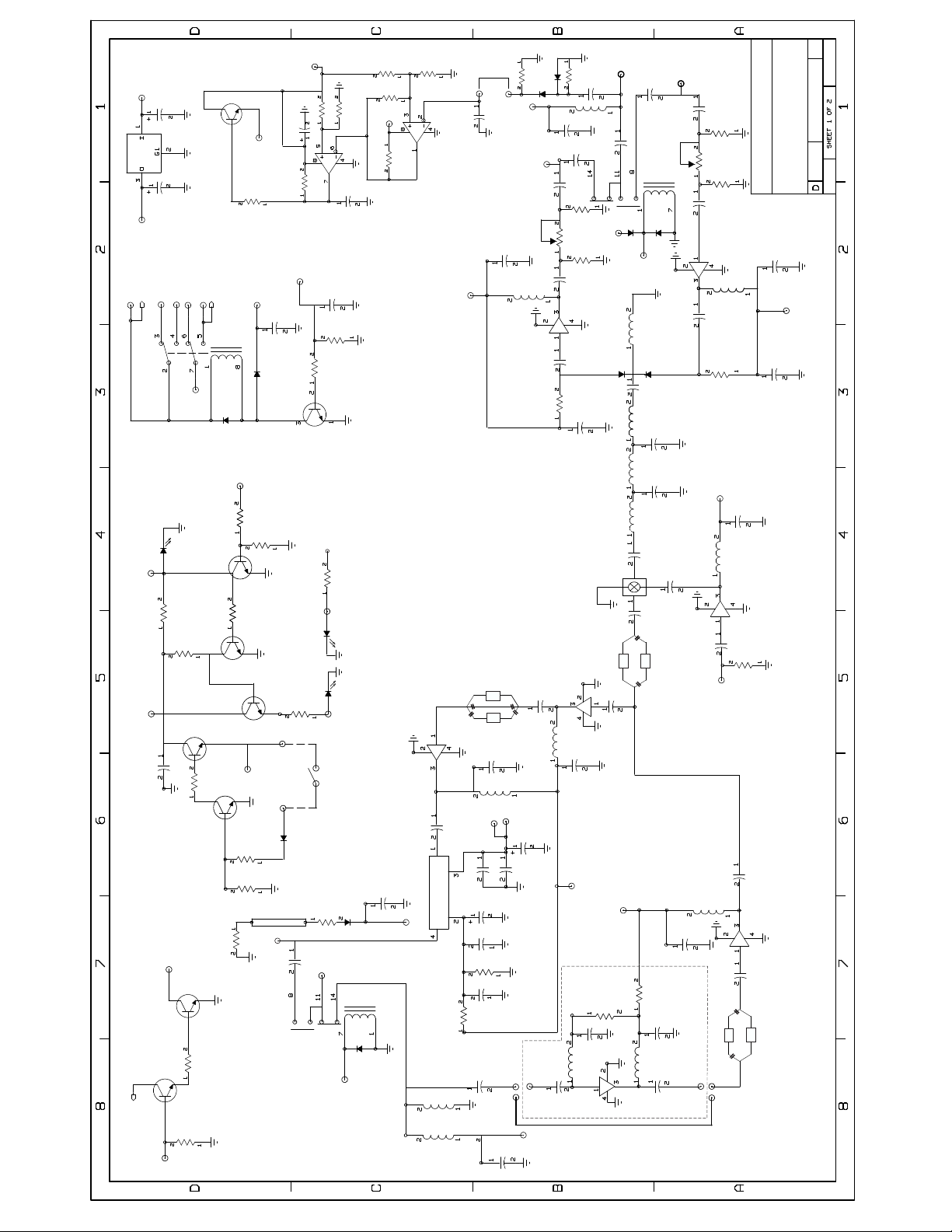
Theory of Operation:
The basic principle of a transverter is to convert a chosen band of
operation to your transceiver of choice. Following the recommendations of the transceiver’s
operation manual for transverter use is the most important aspect of correct transverter operation.
If configured correctly, the transverter will convert both transmit and receive signals to a new band
of operation and be “invisible” to your transceivers operation. In simple terms, the transverter will
not improve the performance of your transceiver but if configured correctly, will not cause any
degradation of performance in any way and will appear as if it was meant to be on that “New” band
all the time.
Interfacing and Operation:
Interfacing the transverter to the transceiver is easy. After
reviewing the front page configuration and verifying that the transverter is configured correctly,
proceed with the directions of interfacing. If you find that something is not correct in the
Transverters configuration, either make the correction by following the directions in the
“Configuration Options” section later in this manual or consult DEMI with your issue.
If you have configured a DEMI transverter before, use the following steps as a guideline to
complete your transverter install. If not, the following steps may be lengthy but are basically
simple. Each step has a brief explanation of how and why the procedure is to be completed. Let’s
review what is required to make this interface complete.

/Built/L23HP.doc 4 12/27/2017
The interfacing starts with a complete understanding of your transceiver and manual. Your
Transceiver’s manual should cover the setup for transverter operation if it has transverter ports and
depict the connections to be made. Some transceivers do not have ports but may still be interfaced
with some instruction. Some transceivers are simple and some are complex. Some transceivers
may have more than one correct way of interfacing. Hopefully, you have decided on how this
transverter is to be interfaced at the time of order so we were able to configure the transverter to fit
your requirements. But remember, all configurations are user changeable and detailed instructions
are included later in this document
.
Start the interfacing with good quality 50 ohm cables for the IF (28 through 144 MHz) and
the 10 MHz connections. These connections are low level (10 watts or less) and are BNC
connectors on the transverter. Your transceiver may have various other types of connections. We
find that simple RG-58 type BNC cables work fine with or without adapters to your transceiver.
All transverters require enabling the Transmit function with a PTT control (Push to Talk to
ground or positive voltage on TX) that follows the transmit mode of the transceiver. The PTT input
to the transverter is PIN 5 of the AUX connector.Most transceivers have RCA connectors for PTT
outputs but some have various different connections. Ready a cable that matches your transceiver
PTT output and attach it to the AUX connector adapter. The adapter connector is supplied and the
numbering matches the Transverters AUX connector Pin out. The PTT input for the transverter is o
Pin 5 and any ground connection (pin 6-8). Then attach the AUX connectors together.
The DC power cable is supplied with the transverter and needs to be prepped on the power
supply end. It is important to fuse this line if using a battery or a high current power supply or
adjust the current limit on your power supply for set up. Review the pictorial below of the rear panel
and the rear panel of the transverter.
DC POWER
ANT/TX RX
10MHZ
AUX
RX IF TX IF
COM
Rear Panel view
Connect your transceiver to the transverter:
Interfacing the transverter to the transceiver
is easy. After reviewing the front-page configuration and verifying that it is configured correctly for
your purpose, begin cabling. An Important note: It is recommended that during the initial setup of
the transverter, do not connect it to your complete system (Final HPA or mast mount LNA). All
aspects of the transverters performance should be tested before a complete installation is made to
an existing system. Drive levels need to be established and proper switching needs to be verified
before complete integration for protection of your existing system.
Remove the bottom cover plate of the transverter leaving the exposed circuit board facing “Up”
After connecting the DC power cable to the power supply of choice, connect the DC POWER to
the transverter. It is a twist lock. 13.8 volts is optimum but the transverter will operate normally from

/Built/L23HP.doc 5 12/27/2017
11 to 15 volts. Remember the fuse! Now cycle the power switch on the transverter and verify that
the “ON” light shows Red. Leave the transverter powered on.
1. The transverter has a synthesized local oscillator with its own reference source but if you
are after extreme accuracy and best phase noise, you can connect an external 10 MHz source of
any type (GPS, TCXO, or Rubidium) at a level of +3 dBm +/- 6dB. When connecting an external
source to the 10 MHz connector, if the level is correct, it will automatically switch in and the Power
“ON” light will turn “Green” to indicate the use of the external source. Remove the external 10 MHz
source connection and the LED will revert back to red. When done playing with the RED/GREEN
lights, power the transverter down. When not using an external source, always terminate the port
with a short or load.
2. Be sure your Transceiver is “Off” and connect the “Push-to-Talk” line from the transverters
AUX connector to your transceiver using the cable made in a previous step. Most transceivers
make a connection to ground during transmit. (PTT-L or to Ground). This connection on your
transceiver may be called something else such as “TX ENABLE”. Some transceivers may source a
positive voltage on Transmit. Review your transceivers manual for keying external devices such as
a Power Amplifier for the correct connection. Consider the transverters keying the same as a
power amplifier. The transverter requires either a connection to ground that sources less than 5
ma or will sink a positive voltage of 2-17VDC at 2 ma.
3. Connect the IF cable/cables. The transverter may have a single common IF port or two
separate ports, TXIF and RXIF. The common port has both TX and RX signals and should connect
to a similar port on your transceiver. Refer to your transceiver’s manual to determine how the IF
connections are to be made if your transceiver is “Transverter Ready”. If the transceiver does not
have transverter ports, you will connect directly to the antenna port of your transceiver. Make
whatever connections you need to do to establish the connection (adapter/adapter cable).
CAUTION: Do not power the transceiver on after making this connection!
4. Antenna Connections. If you have requested a common RF connection, the “ANT/TX” port
has both RF TX and RX functions. If separate TX and RX ports were ordered, the internal transfer
relay of the transverter was bypassed. The separate ports are labeled ANT/TX and RX. No matter
what, connect your antenna system or dummy load with a power meter to the ANT/TX connector
on the transverter. If you have a separate RF RX connection, it would be best to place a 50 Ohm
dummy load on it for initial testing.
.
5. If you have a transceiver without a transverter port and the IF cable is connected to the
antenna port, disconnect it from the Transverter. Now power up your transceiver and depending
on your transceivers function, it may energize the transverter. Set the transceiver to the IF band of
choice that matches the transverter, either 10, 6, or 2 Meters. Then, adjust the output power of the
transceiver to minimum. Even if you have the “Maximum 10 Watt IF Option “installed, the
transverter will operate normally at much less power. This is recommended to eliminate the
possibility of radiated energy within the transverter from the transceivers output power to couple in
to other circuits and produce spurious emissions. The basic transverter only requires a couple of
milli-watts to operate. The 10 watt IF option is a 50 ohm dummy load with a coupling point that
samples a small amount of drive energy in to the TX circuit. The rest is absorbed in the dummy
load but will radiate within the enclosure.
After the transceiver power is adjusted, power off the transceiver and reconnect the IF cable to
the antenna port.

/Built/L23HP.doc 6 12/27/2017
6. Power the Transverter on. If you have an external 10 MHz source, the “On” light should be
green. Now, power on your transceiver and understand that all transceivers are not alike. You
may hear a relay click and the TX light of the transverter may cycle but if the TX light remains on,
power off your transceiver! If the TX light remained on, there is a incorrect connection to the
transceiver regarding the PTT line or your transceiver was locked into transmit. Re-verify the
configuration of the transverter and your transceiver’s manual for keying external devices.
If the set up is working correctly, keying the transverter is as simple as squeezing the MIC button,
or pressing the TX button on the rig. If you test it in the CW mode, do not use Full Break-In !!!!
but increase the delay so not to hear any relay chatter.
The transverter is sequenced and has a built in delay and worst of all, has mechanical relays that
will fail if RF is applied at the wrong time. You can use Semi Break-In,
7. Now, if you have a in line power meter or have been looking at the relative power meter of
the transverter, you have noticed very little output power. This is because the TXIF gain needs
adjustment. Our recommendation is, if using a low level transverter port of your transceiver, and
your transceiver has any method of adjusting the output power of this port set it to maximum output
power.
If you are using the Antenna port for your IF line, adjust your transceivers output power to the
minimum output power it will operate at. The transverter has plenty of adjustment to compensate
its drive level.
Then with a small slotted tuning tool or small screw driver, the TXIF gain control may be
adjusted.The transverters TXIF control is adjusted to maximum attenuation when it left the
factory. Fit the adjusting tool into the slot of the TXIF gain control, place the transceiver in the CW
mode and go key down. Adjust the control to obtain the maximum specified output power or until 9
bars are lit on the relative power meter on the transverter. When complete, verify the SSB mode
and FM if you use it at all. If you transceiver is balanced, all modes should have equal power. On
SSB, it should peak at 9 bars. If you cannot obtain full output power, verify your transverter port
output power. If you are using a High Power IF drive through the antenna connector, do not
assume the output power level is set to low. Verify all possibilities before increasing the output
power of the transceiver. If all fails, consult DEMI with your issues before increasing the drive
power beyond 10 watts.
8. The Receiver gain adjustment is similar. Be sure you have a good antenna, signal generator or
a good dummy load at the desired frequency of use connected to either the antenna port or the
RF RX port. Observe the noise level in the transceiver on the “S” meter and by ear. If it is too
high, adjust the RXIF gain control in the transverter until a slight noise increase is heard in the
transceiver or just a slight movement in the “S” meter is detected. Power the transverter on and off
to verify the change. You should be able to “hear” the difference of on and off. The RX IF gain
may be increased beyond this point, but it will start to degrade the dynamic range of your
transceiver. It is all user preference. If you plan to use an external or mast mount LNA, this level
will need to be re-adjusted. Find a signal on the band or use a signal generator to determine the
minimum signal level.
9. You may re-adjust both RXIF and TXIF again at any time if desired but normally once set,
you forget about it unless you change transceivers or add power amplifiers or receive
preamplifiers. Install the bottom cover. The sequencer AUX connections may be now wired for your
installation. If you require something other than what is indicated on the front page, please see the

/Built/L23HP.doc 7 12/27/2017
Option Setup
section for further details. Also read further about interface and testing a mast
mounted LNA in that section.
10. Basically, the transverter is ready to use in its stand alone form but and may be now
integrated into your more elaborate system. Connect as you wish to use it in your system. If your
system requires the use of the sequencer or you desire to implement it please refer to the Option
Setup
section of this manual.
General Operation:
Some cautions should be taken when operating CW or VOX. Operating the transverter in a
“Full Break-in” mode is not recommended. Because of the mechanical relays and the sequencer in
the transverter, there will be too much delay to operate “Full Break-in” effectively. AND—the relays
would be abused if “Full break-in “is enabled. It is best to operate in “semi break-in” and adjust the
delay of the PTT on your transceiver to match your comfortable CW operating speed in a way that
the delay will hold the PTT until your transmission is complete. Since all transverters will be
delivered with the sequencer enabled, this delay will need to be longer to allow all components
within the system (Power amplifier, LNA, relays, if installed in the system) to complete their
transition if utilized. If the stock transceiver is to be used alone, the transceiver PTT signal may be
connected directly to the transverters PTT input if the sequencer is bypassed. This will shorten up
the delay but will not allow “full break-in” without relay chatter. See the Sequencer Operation in
the
General operation of the transverter, if everything is adjusted correctly,
should be transparent to the transceiver and the user. Except for the frequency read out, (if your
transceiver doesn’t allow its display to be adjusted for transverter operation) it will be like operating
with your transceiver on any other band. All of the functions of the transceiver (filtering, DSP, split
band operation, dual VFO) will be transposed to the frequency band of the transverter.
Option Setup
section of this document.
Option Setup:
Common or Split IF Option:
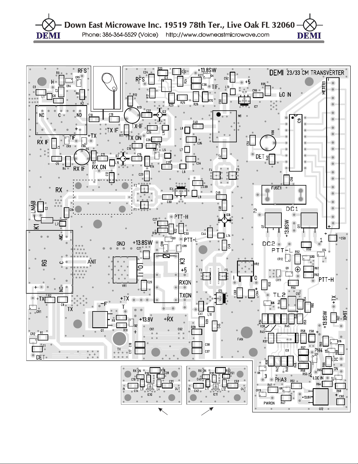
K2 is the common IF relay. To split the IF lines into separate RXIF and TXIF, you only need
to connect the RXIF connector with a short piece of coax to the point on the board between C4 and
C5. Attach the shield of the coax to the cleared metal at that point on ground. Then remove C4.
Leave the common connection at the TXIF input. With this set up, the RF sense protection circuit
and any TX gain or attenuation is still in place. Reverse the procedure if you want to change to or
back to Common IF by installing C4 or use a short piece of wire to bridge the gap.
The IF configuration may be change at any time according to the
type of transceiver you are utilizing. Refer to the Component placement or schematic for
clarification. The component designators are also screened on the circuit board.
TXIF Drive Level Range change:The TXIF drive level range can be changed at anytime to
conform to your transceiver type. Basically, there are 5 configurations for maximum usable drive
levels. For high IF drive levels between 1 and 10 watts, the 50 Ohm load (Load 1) will be installed
with a low value capacitor of either 1 pF for 2M IF frequency and a 5 pF for 10 M operation in the
C13 position. A level up to 1 watt requires a 10 pF for C13 for all IF frequencies. For a level up to
100 mW requires the removal of LOAD 1 and then replace C13 with a 100 ohm chip resistor. Up to
10 mW is the standard level for the transverter and C13 should be a short or a 1000 pF chip
capacitor. Anything below 1 mw will require a gain stage installed in IC2 position At the -10dBM
level, install a MAR3 or any MMIC that will produce around 13dB gain operating at +5VDC at the IF
frequency. If more gain is required, A high gain MMIC will work with inputs as low as -20dBm. To

/Built/L23HP.doc 8 12/27/2017
install IC2, if a chip resistor in its position, it will need to be removed. R13 (the TXIF gain control)
will then need to be re-adjusted for the correct drive level..
IMPORTANT NOTE: When re-testing, do not assume that since your output power of the
transverter is low that it is because you do not have enough IF drive. Please consult DEMI if you
have problems obtaining full output power with your new specified drive level.
Common or Split RF connections:
The RF connections may be reconfigured at any time. If you
desire a separate TX and RXRF connection, install a type “N” connector in the RX hole on the end
panel and connect a coax from it to the point on the board between C9 and the LNA board. The
shield is connected to the exposed metal on ground. Then remove C9. This connection does not
have a DC path to ground to bleed static but it is assumed that if you desire a separate RFRX
connection, you have external protection devices installed. The TXRF (ANT/TX) line remain as it
is. If you have separate ports and wish to make them common, reverse the procedure adding C9
and re-installing L2 if it was removed.
Sequencer:
Step 1 +12VDC on RX for a preamp @ 750 mA maximum
The sequencer in the transverter is ready for operation as specified on the front cover
sheet. Its configuration may be changed at anytime. The transverter is keyed on the 4th and last
step. It is wired to the #4 point on the circuit board in the sequencer section. This is a “LOW” on
transmit. The other connections are indicated on the front page and wired to the AUX connector
with color code.
Step 2 +12VDC on TX for a TR relay (around the preamp) @ 750 mA maximum
Step 3 Ground on TX to key a HP power amplifier. Sinks 100 mA maximum
Step 1 and 2:They can be connected to switch higher DC voltages. The DC voltage is applied to
the DC1 and DC2 connections on the board (30VDC maximum).
Optional Sequencer Connections:
Step 2:TL2 is a secondary connection to the second step. It is a “LOW” on transmit. It can be
used to drive a relay or key an amplifier but an external isolation device should be utilized.
Caution! It will sink 50 mA maximum
Step 3 and Step 4:They have secondary outputs that are both “High” on transmit. They are
labeled PH3 and PH4. These should be isolated from devices that require high currents and are
intended to drive low current devices or Pass transistors or FETs. They will source 50mA.
Sequencer Bypassing: The transverters sequencer may be by-passed to eliminate switching
time delays but is only recommended if it is to be used without any other system components such
as LNAs or power amplifiers. In this case the external PTT input of the transverter, Pin 5 of the
AUX connector may be connected directly to the Amplifier’s PTT input (see component placement
document) between CR9 and C33 labeled PTT-L if using a signal to Ground to key the transverter
or to the PTT-H near R22 if positive voltage keying is utilized. If you bypass the sequencer,
remove the wire coming from the “4” position of the sequencer.
Mast Mount Preamplifier (LNA) Switching: Provisions have been made to provide DC bias
and switching of a mast mount LNA either directly on the ANT or RF RX coax or through the AUX
connector. Step 1 of the sequencer is utilized for any LNA. A fused line is also be implemented.
The socket for the fuse is located under the DIGILO synthesizer board. Remove the two screws
holding the board in place and install a fuse of up to 2 Amps. A 1 Amp fuse is provided (not

/Built/L23HP.doc 9 12/27/2017
installed) when the Mast Mount LNA switching option is ordered. The fused line is directly
connected to the step 1 output. Re-install the two screws. From the output of the Fuse, the DC
power can be routed to a switch mounted on the front panel of the transverter and then to the Pin 1
of the AUX connector or to the LNAB connection on the circuit board near C2 if the mast mount
LNA requires bias on the coax. A choke is installed between the LNAB connection and the RFRX
transmission line acting as a Bias “T”. Then the bias to the LNA is then sequenced or switch out of
line (with the front panel switch) if it is desired to bypass it. See the Components List for the
optional Choke value. CAUTION: Remove L2 from the circuit or the fuse will blow instantly. The
LNAB choke may be repositioned if a separate RFRX port is used. An Auxiliary instruction sheet
for installing DC power on the coax is attached at the end of this document.
Relative Power Meter: The bar graph display is a relative power meter and is driven by the
directional coupler and RF detector circuit found in the Low pass filter section of the board (CR2,
R1,R2,C1) RF is detected and converted to DC voltage and conducted to the Bar graph display on
the front panel. If you find that you operate the transverter at any other level than what we have
calibrated it to 25 watts = 9 bars, you may change it by adjusting VR1 on the display board. It is
located under the Digilo. You may also send the detected voltage out through the AUX connector.
Select an unused pin and make the connection.
Synthesizer Frequency Change:
This is the newest option available. You may select at any
time, any desired IF operating frequency from the list of available frequencies. Just short the two
pads marked with the indicated number specified below with a simple solder connection. The
DIGILO is marked “0-7 Frequency Select”. The selections are listed below.
Frequency of Operation Short pins
1296 = 28 3
1296 = 29
1,3,4,6,7
1296 = 50
0,3,4,6,7
1296 =52
3,4,6,7
1296 = 144
0,1,2
/Built/L23HP.doc 10 12/27/2017
DEM L23HP Component List
Resistors (R) values are in Ohms and are (1206) chips unless otherwise specified.
R1 100
R15 220
R29 51
R43 10K
R57 10K
R2 51
R16 8.2K
R30 8.2K
R44 10K
R58 10K
R3 10K
R17 470
R31
R45 10K
R59 220
R4 220
R18 36
R32 36
R46 10K
R60 10K
R5 1K POT
R19 10K
R33 220
R47 10K
R61 10K
R6 10K
R20 10K
R34 10K
R48 10K
R62 10K
R7 220
R21 Not used
R35 51
R49 10K
R63 1K
R8 Not used
R22 10K
R36 10K POT
R50 470
R64 1K
R9 1K
R23 220K
R37 10K
R51 1K
R65 1K
R10 220
R24 10K
R38 1MEG
R52 22K
R66 10K
R11 220
R25 1MEG
R39 10K
R53 1MEG
R67 470
R12 220
R26 10K
R40 2.7K
R54 10K
R68 10K
R13 1K POT
R27 5.6K
R41 10K
R55 1MEG
R69 1K
R14 220
R28 470
R42 1MEG
R56 10K
R70 10K
Capacitors (C) values are in ρF and are (0805) chips unless otherwise specified.
“T” = chip Tantalum, Band is positive.T
C1 100 (1206)
C17 0.1
µ
F (1206)
C33 1000
C49 100
C2 100 (1206)
C18 100 (1206)
C34 27
C50 100
C3 1000 (1206)
C19 33 (0603)
C35 27
C51 33
C4 1000
C20 0.1
µ
F (1206)
C36 0.1
µ
F (1206)
C52 0.1
µ
F (1206)
C5 1000
C21 4.7 or 10µF T
C37 0.1µF (1206)
C53 100
C6 1000
C22 1000
C38 100
C54 0.1
µ
F (1206)
C7 3
C23 1000
C39 0.1
µ
F
C55 100
C8 33 110mil
C24 1000
C40 1000
C56 0.1
µ
F
C9 100
C25 0.1
µ
F
C41 0.1
µ
F
C57 22
µ
F
C10 1000
C26 1000
C42 100
C58 4.7 or 10
µ
F T
C11 1000
C27 1000
C43 33 (0603)
C59 4.7 or 10
µ
F T
C12 0.1
µ
F
C28 33
C44 0.1
µ
F
C60 10
µ
F
C13 configuration C29 1000 C45 100
C61 100
µ
F
C14 100
C30 100
C46 100
C62 100
µ
F
C15 1000
C31 100
C47 100
C63 0.1
µ
F (option)
C16 1000
C32 4.7 or 10
µ
F T
C48 100
C64 4.7 or 10
µ
F T (option)
All inductors are specified.
L1 1000nH (1008) (option)
L10 1000nH (1008)
L2 1000nH (1008)
L11 33 nH (0603 chip inductor)
L3 33 nH (0603 chip inductor)
L12 33 nH (0603 chip inductor)
L4 33 nH (0603 chip inductor)
L13 1000nH (1008)
L5 1000nH (1008)
L14 1000nH (1008)
L6 39nH (1008)
L15 1000nH (1008) (option)
L7 82nH (1008)
L16 1000nH (1008) (option)
L8 39nH (1008)
L17 0.33
µ
H molded choke (option)
L9 1000nH (1008)

/Built/L23HP.doc 11 12/27/2017
Solid State, Relays and Filter Components
Q1 MJD31
CR1 MMBD914
IC3 LM393
Q2 PMBT3904
CR2 HSMS-2800
IC4 PGA103
Q3 PMBT3904
CR3 MMBD914
IC5 PGA103
Q4 PMBT3904
CR4 HSMS-2800
IC6 MAR3
Q5 PMBT3904
CR5 HSMS-2800
IC7 PHA-1
Q6 PMBT3904
CR6 MMBD914
IC8 LM324
Q7 MJD32
CR7 HSMP3814
IC9 LM3914
Q8 PMBT3904
CR8 MMBD914
IC10 PMA2-33LN
Q9 PMBT3904
CR9 MMBD914
IC11 PMA2-33LN
Q10 PMBT3904
CR10 MMBD914
METER1 BARGRAPH
Q11 MJD31
CR11 MMBD914
M1 SYM-18H
Q12 MJD32
CR12 MMBD914
VR1 L7805CD2
Q13 PMBT3904
F1 1296MHz(N95x)
VR278M09 (optional)
Q14 PMBT3904
F3 1296MHz(N95x)
K1 RG-1
Q15 PMBT3904
F4 1296MHz(n95x)
K2 G6Y
Q16 PMBT3904
IC1 MAR3 (option)
K3 G5V
Q17 PMBT3904
IC2 MAR6 (option)
FUSE 1Amp
IC12 RA18H1213G
LOAD MP930
TH Thermistor
/Built/L23HP.doc 12 12/27/2017
L1 7
LOAD
IC1 2
LNA MODULES
(M I G HT BE I NS T AL L E D)
LNA MODULE
10/2017
rx if
TRANS
L23HP Transverter
C6
C4
Cr3
tif
K2
C10
TX ON
C41
Ic5
L10
R2
R1
Cr2
C1
DET
+TX
Cr6
ANT
K1 C8
Ic1
C45
R29
R28 C38 C62
C17
+13.8V
C61
C37
C18
C9
L2
oPTION
“l17”
C2
Ic4
C30
F2
F1
C44 Ic6
L14
C48
F4
F6
C35
C39
L9
C45
Ic1
C15
C12
L15
F3
F5
C49
if
rf
lo
m1
C50
tx if
C13
R13
R12
R11
C22
Ic2
C26
C25
L16
C16
R15
tx on
C5
R5
R4
R7
C11
rx on
L5
L6
C29
L7
L8 Cr7
C47 C40
C34
C23
R14
Ic7
C55
L13
R35
C52
LO in +5
rX ON
C3
L1
h
C3
Cr4
R3
R6
rfs
rfs
C24
C36
C32
R17
R25
R23
R70
R26
R24
R25
R27
q4
+13.8sw
+13.8sw
tif
ic3
Q1 -F
T
R9
Q2
R10
+13.8 V
Ic4
C31
c53
C19
c43
L4
l12
L3
l11
C14
c42
in
R16
r30
R18
r32
out
C28
c51
RX
LNAB
BYPASS
+13.8 SW
+RX
+TX
rx on
tx on
PTT -L
+5
Cr8
Cr9
PTT -H
Q3
R22
C27
C33
R19
K3
C21 C20
+13.8sw
Vr1
+5
JUMPER
“loc” +TX
loc in
+13.8 V
“ON”
R66
R41
Q8
Cr10
R47
Q12
R51
R67
xmit
Manual siwtch
Pwr on
R69
C60
+
Q15
Q16
R63
R68
R65
R64
Q17
loc
ON
+13.8sw
“XMIT”
GAIN
ADJUST
GAIN
ADJUST
TX
rf and dc control
+tx
Cr6

L23HP TRANSVERTER
10/2017
tx = h
ph4
4
3
q5
tx = h
phA3
q13
r46
r48
r56
r57
r39
r42
+13.8 SW
r57 r55
cr13
c57
r43
r53
r45
r38
r34
q6
r37
tx=l
tl2
r33
q7
2
dc 2
q14
q11
r59
dc 1
1
+13.8 sw
c58
r49
r60
+
r50
r44
r52
cr12
q9
ptt - l
ptt -h
r62
q10
r61
ic8
rx tx
high open
low
open
open
open low
high
1
2
3
4
+13.8 sw
det
c59
c54
c56
R40
ic9
r36
meter 1
r54
LNAB
FUSE 1
sequencer and meter
Table of contents
Other demi Media Converter manuals


Popular Media Converter manuals by other brands

ATEN
ATEN VC812 user manual

Patton electronics
Patton electronics 222N, 222NS user manual

DirekTronik
DirekTronik EL2315 quick start guide

Belden
Belden Grass Valley K-Frame Installation & service manual

Transition Networks
Transition Networks CGETF10XX-10X user guide

Uhlenbrock Elektronik
Uhlenbrock Elektronik 75900 user manual

Rose electronics
Rose electronics CNV-VGADVISC Installation and operation manual

Interlogix
Interlogix MCR300-1T user manual

ZIGBEE
ZIGBEE ATC-3200 user manual

Kenwood
Kenwood SS-992 instruction manual

Linear Technology
Linear Technology LT1952-1 quick start guide

Cross Technologies
Cross Technologies 2415-02 Series instruction manual


