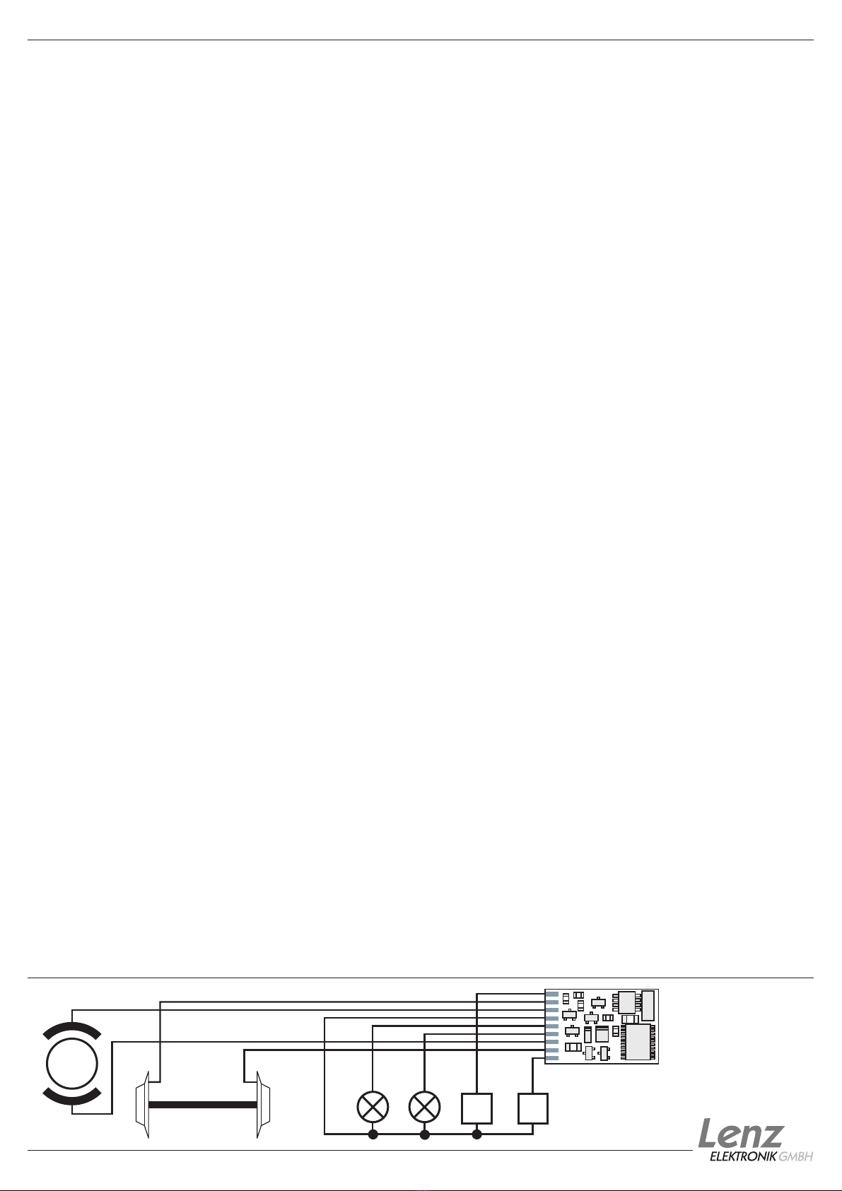
manuals.online logo
Brands
  1. Home
  2. •
  3. Brands
  4. •
  5. Lenz
  6. •
  7. Media Converter
  8. •
  9. Lenz Digital plus LE1014A Owner's manual

Lenz Digital plus LE1014A Owner's manual

Information LE1014A
Art. Nr. 10125
2. Auflage / 2nd Edition
03 03
Seite / Page: 1
Information LE1014A Art. Nr. 10125
Technische Daten ........Technical data ...........Données techniques
"Silent Drive" Betrieb: ......"silent drive" operation:
Maximale Belastbarkeit . . . current carrying capacity . . . Charge totale maximale
des gesamten Decoders...ofthedecoder in sum ...... ..........1,0A
Motorausgang...........motor output .............Sortie moteur .................0,9A
Funktionsausgang A und B . function output A and B ....Sorties de fonction A et B......150mA
Funktionsausgang C.......function output C .........Sortie de fonction C ..........500mA
Lokadressen .............addresses ...............Adresses de locomotive ......1-9999
Fahrstufen ..............speed steps .............Crans de marche ......14,27,28,128
Abmessungen............dimensions ..............Dimensions: .....31,5 x 16,0 x 3,8 mm
autorisée du décodeur
Maximale Belastbarkeit . . . current carrying capacity . . . Charge totale maximale
des gesamten Decoders...ofthedecoder in sum ......autorisée du décodeur ...........1A
Motorausgang...........motor output .............Sortie moteur...................1A
Funktionsausgang D.......function output D .........Sortie de fonction D ..........150mA
Normalbetrieb ............normal operation:
Eigenschaften:
l
l
l
l
l
l
getrennt einstellbare Anfahr- und
Bremsverzögerung
Programmieren während des Betriebes
Mehrfachtraktion
2 Funktionsausgänge A und B, einstellbar
auf: richtungsabhängige Funktion (F0),
Ausgang A vorwärts aktiv, Ausgang B
rückwärts aktiv
einzeln schaltbar: Ausgang A reagiert auf F0,
Ausgang B reagiert auf F1
einzeln dimmbar
Marslight, Gyrolight, Strobe, Double Strobe
Betrieb auf Gleichstromanlage
(Analogbetrieb) möglich. Diese Eigenschaft
ist abschaltbar.
l"Silent Drive" hochfrequente
Motoransteuerung zur Geräuschreduzierung.
Funktionsausgänge C und D:
Reaktion auf F1 bis F8 frei einstellbar
(Mapping); Blinkbetrieb; Ditchlight
(abwechselndes Blinken)
Kabelanschluß zum Anlötenl
Wichtige Sicherheitshinweise
Digital plus Lokdecoder dürfen ausschließlich
verwendet werden mit Lenz DIGITAL plus oder einer
anderen handelsüblichen Digitalsteuerungen mit NMRA-
Konformitäts-Siegel. Fragen Sie im Zweifelsfall beim
Lieferanten des Systems nach.
Wickeln Sie aber den Lokempfänger nie in
Isolierband ein, hierdurch wird die notwendige
Luftzirkulation um den Empfänger verhindert. Kleben Sie
vielmehr die Metallteile der Lokomotive mit Isolierband
o.ä. ab. Hierdurch können Sie ungewollte Kurzschlüsse
vermeiden, ohne daß der Empfänger 'erstickt'. Fixieren
Sie den Empfänger mit doppelseitigem Klebeband.
Bevor Sie einen Digital plus Lokempfänger einbauen,
prüfen Sie die Lokomotive vor dem Umbau im normalen
Gleichstrombetrieb auf einwandfreie Funktion. Ersetzen
Sie verschlissene Kohlen und durchgebrannte Birnchen.
Nur eine Lok mit einwandfreier Mechanik kann mit
einem Lokempfänger einwandfrei fahren.
Die in den technischen Daten angegebenen
Belastbarkeiten dürfen nicht überschritten werden. Sie
müssen sicherstellen, daß diese maximale Belastbarkeit
nicht überschritten wird. Bei einer Überlastung wird der
Empfänger zerstört! Die Bauteile des Lokempfängers
dürfen auf keinen Fall Metallteile des Chassis oder des
Lokgehäuses berühren. Es entsteht ein Kurzschluß
innerhalb des Lokempfängers, und er wird zerstört.
Mit Digital plus Decodern ausgerüstete Lokomotiven
dürfen auf Zweileiteranlagen nicht an der Oberleitung
betrieben werden, da die Lokomotive durch Aufgleisen
in der falschen Richtung die doppelte Fahrspannung
erhalten kann. Hierbei wird der Lokempfänger zerstört!
Features:
l
l
l
"Silent Drive" high frequency motor operation
reduces noise
Function outputs D and C:
mapping to F1 through F8; blinking; Ditchlight
cable connection
l
l
l
l
l
acceleration and deceleration seperately
adjustable
Programming on Main
multi unit capability (advanced consisting)
2 function outputs A and B may be
configured in many ways: depending on
direction (F0), output A forward active, output
B reverse active or individually, output A
reacts on F0, output B reacts on F1
outputs can be dimmed
Marslight, Gyrolight, Strobe, Double Strobe
Operation on standard DC systems
(analogue operation) possible. This feature
can be disabled.
Propriétés :
l
l
l
l
l
l
l
Commande de moteur à haute fréquence
"Silent Drive" pour atténuation du bruit.
Temporisations d'accélération et de freinage
réglables séparément
Programmation pendant la marche (PoM)
Multitraction
2 sorties multifonctions, réglables de diverses
façons:Fonction (F0) avec inversion selon le
sens de marche, sortie A active en marche
avant, sortie B active en marche arrière,
Commutation individuelle : la sortie A réagit à
F0, la sortie B réagit à F1
Dimming (réglage intensité) individuel
Marslight (gyrophare lent), Gyrolight
(gyrophare rapide), Strobe (flash), Double
strobe (double flash)
Sorties de fonction C et D:
Mapping (attribution) au choix sur F1 à F8;
Blinking (clignotement); Ditchlight
(clignotement en alternance)
Exploitation possible sur réseaux à courant
continu (exploitation analogique). Cette
option peut être désactivée.
lavec câbles de liaison à souder
Important safety instructions:
The Digital plus locomotive decoders are to be used
only with Lenz Digital plus or other standard digital
control with an NMRA-conformance seal. If in doubt, ask
the system suppliers.
Note the maximum current-carrying capacity of the
outputs must not be exceeded. Exceeding this will
destroy the decoder! The parts of the locomotive
decoder must not on any account touch the metal
components of the chassis or the body of the
locomotive. This could cause a short-circuit within the
locomotive decoder which might destroy it.
Never wrap the locomotive decoder in insulating tape,
as this prevents the necessary air circulation around the
decoder. Instead, put insulating tape or something
similar around the metal components of the locomotive.
By doing so you can avoid unintentional short-circuits
without depriving the decoder of air. Use double-sided
adhesive-tape to affix the decoder.
Locomotives equipped with Digital plus decoders
must not be run using powered overhead line either on
conventional DC control or DCC control This could
subject the locomotive to double the voltage and this
would destroy the decoder.
The current carrying capacities noted in the technical
data above may not be exceeded.
Before installing a Digital plus Decoder, check the
loco in normal DC operation to make sure that it works
as it should before modifying the locomotive.
Replace worn wheel contacts, motor brushes and
blown bulbs. Only a locomotive that is mechanically OK
will function properly with a locomotive decoder.
Remarques importantes
Tout décodeur Digital plus est exclusivement destiné à
être utilisé avec Lenz DIGITAL plus ou un autre système
de pilotage digital du commerce portant le sigle de
compatibilité NMRA. En cas de doute, demandez des
explications au revendeur du système.
Les charges mentionnées dans les données techniques
ne peuvent pas être dépassées. Vous devez vous
assurer que la charge totale maximale n'est pas
dépassée. En cas de surcharge, le décodeur serait
détruit ! Il ne faut, en aucun cas, que les éléments du
décodeur soient en contact avec des parties métalliques
du châssis ou de la caisse de la locomotive. Il
surviendrait un court-circuit à l'intérieur du décodeur et
celui-ci serait endommagé.
N'enroulez jamais votre décodeur dans une toile
isolante, car cela empêcherait la libre circulation de l'air
autour du décodeur. Isolez plutôt les parties métalliques
de la locomotive avec de la toile isolante ou autre
procédé. Ce faisant, vous éviterez les courts-circuits
indésirables sans que le décodeur "étouffe" de chaleur.
Fixez le décodeur à l'aide d'un bout de bande à double
face adhésive.
Sur des réseaux à deux rails, les locomotives avec
décodeur ne peuvent pas être alimentées en courant
par la caténaire ; en effet, elles pourraient capter une
tension d'alimentation doublée en étant posée sur les
rails dans le mauvais sens. Dans ce cas, le décodeur
serait détruit !
Avant d'installer un décodeur Digital plus, vous devez
soumettre la locomotive à un essai de marche
irréprochable en mode d'exploitation conventionnelle à
courant continu. Remplacez les balais de moteur usés
et les ampoules grillées. Seule une locomotive pourvue
d'une mécanique impeccable peut rouler
irréprochablement avec un décodeur.
Motor
ACDBFF
Orange
Grün
Green
Vert
Violett
Purple
Information LE1014A
Seite / Page: 2
Einbau des LE1014A
Notieren Sie sich, welcher Motoranschluß mit
den rechten und welcher mit den linken
Radschleifern verbunden ist. Dies erspart Ihnen
beim Anschluß des Lokempfängers Versuche,
welches Kabel des Lokempfängers an welchen
Motoranschluß gelötet werden muß, um die
richtige Fahrtrichtung einzustellen.
Die Motoranschlüsse müssen nach Entfernen
der bisherigen Kabel potentialfrei sein. Das heißt,
sie dürfen keine Verbindung zum Chassis oder
den Lokrädern (Radschleifern) mehr haben.
Achten Sie auch darauf, daß solche
Verbindungen mitunter erst durch Aufsetzen des
Gehäuses entstehen können!
Wenn Sie sich nicht sicher sind, ob alle
Voraussetzungen zum Einbau erfüllt sind,
wenden Sie sich an einen Servicebetrieb
Schließen Sie den Lokempfänger zuerst an die
Radschleifer an:
rotes Kabel an die in Fahrtrichtung rechten
Radschleifer
schwarzes Kabel an die in Fahrtrichtung
linken Radschleifer.
Dann verbinden Sie den Empfänger mit den
Motoranschlüssen:
oranges Kabel an den Motoranschluß, der
vorher mit den rechten Radschleifern
verbunden war
graues Kabel an den Motoranschluß, der
vorher mit den linken Radschleifern
verbunden war.
Nun schließen Sie die Funktionen an. Im
Auslieferungszustand sind diese
Funktionsausgänge wie folgt eingestellt:
Ausgänge A und B reagieren
fahrtrichtungsabhängig auf F0. Diese Einstellung
kann geändert werden.
Wenn Sie die Funktionsausgänge in der
Werkseinstellung verwenden möchten, dann
verbinden Sie die Ausgänge wie folgt:
Funktionsausgang A (weißes Kabel) an das
in Fahrtrichtung vordere Birnchen,
Funktionsausgang B (gelbes Kabel) an das
in Fahrtrichtung hintere Birnchen.
Sind die Glühbirnchen nicht elektrisch mit dem
Chassis der Lokomotive verbunden (wir nennen
diese dann "potentialfrei"), so schließen Sie nun
noch den anderen Pol der Lampen an das blaue
Kabel an, wie in der Abbildung zu sehen. Besteht
eine Verbindung zwischen Glühbirnen und
Chassis, so bleibt das blaue Kabel unbenutzt. Bei
Anschluß am blauen Kabel leuchten die
Glühbirnen etwas heller, außerdem funktioniert
dann die richtungsabhängige Beleuchtung auch
im Betrieb mit normalem Gleichstrom. Welche
der Varianten Sie umsetzen, hängt von der
Konstruktion der Lokomotive ab.
Für den Anschluß von Leuchtdioden gilt:
Blaues Kabel ist "Pluspol" (Anodenseite der
LED), Funktionsausgang ist "Minuspol"
(Kathodenseite der LED). Die Spannung am
Funktionsausgang beträgt ca. 16V. Vergessen
Sie nicht den erforderlichen Vorwiderstand
l
l
l
l
l
l
Schließen Sie nun noch den
Funktionsausgang C und D an, sofern eine
weitere Funktion in Ihrer Lok vorhanden ist.
Funktionsausgang C (grünes Kabel) an
eine weitere Funktion.
Funktionsausgang D (violettes Kabel) an
eine weitere Funktion.
l
l
Installation of the LE1014A
Take note of which motor connection is linked
to the right-hand locomotive wheels and which to
the left. If you do this you will not have to try out
which cable of the decoder needs to be soldered
to which connection of the motor in order to
achieve the desired direction of travel.
After the removal of the original connections to
the motor brushes, both the motor brushes must
be potential free and completely isolated from
both tracks. This means that they must not be
connected in any way to the chassis or to the
wheels of the locomotive. Also bear in mind that
such connections are sometimes created only
when the chassis is put back!
Please contact a service centre if you are in
any doubt as to whether all preconditions for the
installation are fulfilled!
First connect the decoder to the pick-ups from
the wheels of the locomotive:
red cable to the wheels which in relation to
the direction of travel are on the right-hand
side of the locomotive
black cable to the wheels which in relation
to the direction of travel are on the left-hand
side of the locomotive
Then connect the decoder to the motor
connections:
orange cable to the motor connection
previously connected to the right-hand
locomotive wheels
grey cable to the motor connection
previously connected to the left-hand
locomotive wheels.
Now connect the functions. Ex-works default
settings for the functions are configured as
follows: function outputs A and B as direction-
dependent outputs reacting to F0. This
configuration can be altered as desired.
If you wish to use the function outputs in their
initial configuration then connect the outputs as
follows:
function output A (white cable) to the bulb
which in relation to the direction of travel is
at the front
function output B (yellow cable) to the bulb
which in relation to the direction of travel is
at the back
If the functions inside the locomotive (e.g. the
bulbs of the direction dependent lights) are not
electrically connected to the chassis of the
locomotive (i.e; if they are, "potential free") then
connect the other pole of the function to the blue
cable, as shown in the illustration. If a connection
between functions and chassis does exist, then
the blue cable remains unused. When connected
to the blue cable the bulbs shine somewhat
brighter and, in addition, the direction dependent
lighting then also works in normal DC operation.
Which option you choose depends on the design
of the locomotive.
For the connection of LEDs note that the blue
cable is the positive pole (anode side of the LED)
and the function output the negative pole
(cathode side of the LED). The voltage at the
function output is approximately 16 V. Please do
not forget the necessary protective resistor.
l
l
l
l
l
l
Now connect the outputs C and D (if your
locomotive has further functions):
function output C (green cable) to another
locomotive function.
function output D (purple cable) to a
another locomotive function.
l
l
Montage du décodeur LE1014A
l
l
sortie C (câble vert) à un dispositif de
fonction;
sortie D (câble violet) à un autre dispositif
de fonction.
Notez la correspondance entre les bornes du
moteur et les patins de prise de courant droits et
gauches. Ceci vous évitera de rechercher, lors du
raccordement du décodeur, quels câbles du
décodeur vous devrez souder aux bornes de
sortie du moteur pour que la locomotive roule
dans le bon sens.
Les sorties du moteur doivent être au potentiel
zéro après enlèvement des câbles préexistants.
Cela signifie qu'il ne doit subsister aucune liaison
avec le châssis ou avec les roues (ou patins de
roue). Veillez aussi à ce qu'une telle liaison ne
puisse survenir par inadvertance lors de la
repose de la caisse !
Si vous avez des doutes sur la conformité de la
transformation de la locomotive, adressez-vous
alors à un service compétent !
Raccordez tout d'abord le décodeur de
locomotive aux patins de roue :
Maintenant, raccordez les dispositifs de
fonction aux sorties de fonction. Voici les
réglages d'usine de celles-ci : les sorties A et B
réagissent à F0 avec inversion selon le sens de
marche et les sorties C et D réagissent à F1 et
F2. Ces réglages peuvent être modifiés.
Si vous êtes d'accord d'utiliser les sorties de
fonction telles que réglées en usine, raccordez
alors les sorties comme suit :
Si le second pôle des ampoules n'est pas relié
électriquement au châssis de la locomotive
(donc, s'il est au potentiel zéro), raccordez-le au
câble bleu (voir illustration). S'il existe une liaison
entre les ampoules et le châssis, le câble bleu
n'est pas utilisé. En cas de retour de courant par
le câble bleu, les ampoules brilleront davantage.
En outre, les feux de signalisation (avec inversion
selon le sens de marche) fonctionneront
également en exploitation conventionnelle en
courant continu. Quelle que soit la variante
choisie, elle est essentiellement dépendante du
type constructif de la locomotive.
Si votre locomotive est équipée de diodes
lumineuses, tenez compte de ceci : câble bleu =
pôle "plus" (anode de la diode) ; sortie de
fonction = pôle "moins" (cathode de la diode). La
tension entre la borne de sortie et le câble bleu
étant d'environ 16 V, n'oubliez pas de placer une
résistance adéquate en série.
Raccordez maintenant les sorties de fonction
C et D pour autant que d'autres dispositifs de
fonction existent sur votre locomotive :
l
l
l
câble rouge aux patins droits dans le sens
de marche ;
câble noir aux patins gauches dans le sens
de marche.
Ensuite, raccordez le décodeur aux sorties
moteur :
câble orange à la sortie moteur qui était
auparavant raccordée aux patins droits ;
câble gris à la sortie moteur qui était
auparavant raccordée aux patins gauches.
sortie A (câble blanc) à l'ampoule avant
(selon sens de marche sélectionné) ;
sortie B (câble jaune) à l'ampoule arrière
(selon sens de marche sélectionné).
l
l
l
Anschluß des LE1014A
Wiring the LE1014A
Montage du décodeur
LE1014A
Grau
Grey
Gris
Rot
Red
Rouge
Schwarz
Black
Noir
Weiß
White
Blanc
Gelb
Yellow
Jaune
Blau
Blue
Bleu
Seite / Page: 3
Test des Einbaus
Stellen Sie (ohne das Gehäuse aufzusetzen)
die Lokomotive auf das Programmiergleis und
lesen Sie die Adresse aus. Bei Auslieferung ist
der Empfänger auf die Adresse 03 programmiert.
Wenn Sie den Empfänger bis hierher richtig
angeschlossen haben, so sollten Sie diese
Adresse auslesen können. Ist dies nicht der Fall,
so ist Ihnen bei der Verkabelung möglicherweise
ein Fehler unterlaufen. Kontrollieren und ändern
Sie ggf. die Verkabelung.
Nun können Sie mit der Lokomotive auf Ihrer
Anlage zur ersten Probefahrt starten.
Testing the installation
Place the locomotive on the programming track
(without its housing) and read the address. Ex-
works, the decoder is programmed to the
address 03. If you have connected the decoder
correctly thus far you should now be able to read
the address. If you are not able to do so it is
possible that you have made a mistake when
connecting the cables. Do not subject the loco to
full running track power until you obtain the
correct "03" address read-out. Check the cable
connections and change them as required. You
should now be able to send your locomotive on
its first test run on your layout.
Test après montage
Posez maintenant la locomotive (avant de
remettre la caisse sur le châssis) sur la voie de
programmation et sélectionnez l'adresse. En
usine, le décodeur est d'office programmé sur
l'adresse 03. Si vous avez raccordé correctement
le décodeur, vous devriez pouvoir lire cette
adresse. Si ce n'est pas le cas, une faute vous a
peut-être échappé lors du câblage. Contrôlez et
modifiez le câblage le cas échéant.
Vous pouvez maintenant procéder à un premier
essai de marche sur votre réseau.
Programmierung des Lokempfängers.
Lokadresse, Anfahr- und Bremsverzögerung
sowie alle anderen Eigenschaften des
Lokempfängers können durch
PROGRAMMIERUNG beliebig oft geändert
werden. Diese Eigenschaften werden im
Lokempfänger dauerhaft, also auch beim
Abschalten der Betriebsspannung, "aufgehoben".
In der (amerikanischen) Normung werden die
Speicher als "Configuration Variable", kurz: "CV"
bezeichnet. Das Einschreiben/Auslesen der
Werte erfolgt elektronisch, die Lokomotive muß
also nach Einbau des Empfängers nicht mehr
geöffnet werden. Zur Programmierung des
Lokempfängers können folgende Digital plus
Geräte eingesetzt werden:
Zentrale LZ100 / LZV100(mit einem
Handregler LH100) oder dem Interface
LI100 / LI100F.
SET02
compact
Wie die Programmierung im Einzelnen
durchgeführt wird, erfahren Sie aus den
Betriebsanleitungen der genannten Geräte.
Der Decoder ist im Lieferzustand auf Betrieb
mit Adresse 3, 28 Fahrstufen, interner
Geschwindigkeitskennlinie, Funktion nicht
gedimmt eingestellt. Der Decoder kann sofort mit
diesen Einstellungen verwendet werden. Die
Einstellungen können selbstverständlich
geändert werden.
l
l
l
Programmation du décodeur
C
VCV
Au moyen de la PROGRAMMATION, on peut
modifier à volonté l'adresse de locomotive, les
temporisations d'accélération et de freinage ainsi
que toutes les autres propriétés du décodeur.
Ces propriétés sont "conservées" de manière
permanente au sein du décodeur, même après
avoir débranché le courant d'alimentation. Dans
les normes (américaines), les emplacements
mémoriels sont désignés " onfiguration
ariable", en abrégé " ". L'encodage et la
lecture des valeurs mémorisées se font
électroniquement de sorte que la locomotive ne
devra plus jamais être ouverte une fois le
décodeur installé.
Pour programmer les décodeurs de locomotive, il
faut disposer des appareils suivants :
compact.
En ce qui concerne la programmation en
particulier, voyez les instructions accompagnant
les appareils susmentionnés.
En usine, le décodeur est réglé sur l'adresse
de base 3, sur le mode de marche à 28 crans,
sur la courbe caractéristique interne de vitesse et
avec intensité (dimming) des fonctions non
atténuée. Tous ces réglages sont évidemment
modifiables.
l
l
l
Centrale LZ100 / LZV100 (avec un
régulateur LH100) ou interface LI100 /
LI100F;
SET02 ;
Programming the decoder.
The locomotive address, acceleration and
deceleration delay, and all other features of the
locomotive decoder can be changed as often as
desired by reprogramming. The features are
"stored" permanently in special locations even
when the operational voltage is switched off.
These locations are called "configuration
variables" or simply CV. The configuration of the
values is done electronically, which means that it
is not necessary to open the locomotive again
after the decoder has been installed.
To program the locomotive decoder you need
one of the following Digital plus systems:
LZ100 / LZV100 with manual controls
LH100/ LH200 or the interface LI100 /
LI100F
SET02
compact
For detailed instructions on how to program
using the devices mentioned, please refer to the
operating instructions which accompany those
devices.
On delivery the decoder is programmed for
operating with the basic address 03, 28 running
notches and an internal speedline. The decoder
can be used immediately on purchase with these
basic configurations. All configurations can, of
course, be changed.
l
l
l
Liste der unterstützen CVs ..............................List of used CVs ....................Liste des CV prises en charge ..........
plus faible
als auch im conventional aussi bien digitale que conventionnelle .....
enCV1....
Decoder uses CV17 and CV18 .........Décodeur avec adresse étendue en........
....... ........undCV18 ..........................asaddress .........................CV17 et CV18
CV . . min-max def. . CV Definition.......................CVdefinition .......................Définition de la CV ....................
1. . . 1-99 .....3..Basisadresse .......................Locomotive address ..................Adresse de base.......................
2. . . 0-31 ....16..Anfahrspannung.....................starting voltage ......................Tension minimale de démarrage ..........
3. . . 1-255 ....1..Anfahrverz..........................Acceleration delay ...................Temporisation d'accélération .............
4. . . 1-255 ....1..Bremsverz. .........................Deceleration delay ...................Temporisation de freinage ...............
7...-... ....46..Versionsnummer ....................Version number .....................Numéro de version .....................
8...-... ....99..Herstellernummer....................Manufacturer ID .....................Code du constructeur ...................
17...........0..erweiterte Adresse, höherwertiges Byte . . extendend address, high byte ..........Adresse étendue, octet de niveau le .......
....... ........ .................................. ..................................plus élevé
18...........0..erweiterte Adresse, niederwertiges Byte . . extendend address, low byte ...........Adresse étendue octet de niveau le
19 . . 1-99 .....0..Mehrfachtraktionsadresse .............Multi unit (consist) address.............Adresse pour la traction multiple ..........
29..Bit.......6..Decoder Einstellungen 1 ..............Decoder configuration 1 ...............Réglages niveau 1 .....................
...1...'0'...'0'..Richtung normal .....................direction normal .....................Sens de marche normal .................
.......'1' ......Richtung invertiert ...................direction inverted ....................Sens de marche inversé.................
...2...'0' ......14/27Fahrstufen ...................14/27speed steps ..................Mode de marche à 14 / 27 crans ..........
.......'1'...'1'..28/128Fahrstufen ..................28/128speed steps .................Mode de marche à 28 / 128 crans .........
...3...'0' ......Lokfährt nur im Digitalbetrieb ..........locomotive operates in digital mode only . . La locomotive ne roule qu'en .............
....... ........ .................................. ..................................exploitation digitale .....................
.......'1'...'1'..Lokfährt sowohl im konventionellen .....locomotive operation possible on both ...Lalocomotive roule en exploitation ........
....... ........ digitalen Betrieb ........... DCandDCC.............
...4... ....'0'..immer 0 ...........................always 0 ...........................Toujours 0 ............................
...5...'0'...'0'..werksseitige Kennlinie ................factory pre-set speed curve is used ......Courbe caractéristique de vitesse .........
....... ........ .................................. ..................................encodée en usine ......................
.......'1' ......benutzerdefinierte Kennlinie............user defined speed curve is used........Courbe caractériser. de vitesse définie .....
....... ........ .................................. .................................. parl'utilisateur ........................
...6...'0'...'0'..Decoder benutzt Basisadresse aus CV1 . . Decoders uses CV1 as address.........Décodeur avec adresse de base
.......'1' ......Decoder benutzt Adresse aus CV17 .....
...7... ....'0'..immer 0 ...........................always 0 ...........................Toujours 0 ............................
...8... ....'0'..immer 0 ...........................always 0 ...........................Toujours 0 ............................
Information LE1014A
Seite / Page: 4
CV . . min. max def. . CV Definition.......................CVdefinition .......................Définition de la CV ....................
50..bit.. ........Decoder Einstellungen 2 ..............Decoder configuration 2 ...............Réglages niveau 2 .....................
...1... ........nicht benutzt........................notused ...........................Nonutilisé............................
...2... ........nicht benutzt........................notused ...........................Nonutilisé............................
...3...'1'...'0'..bremsen im Analogbetrieb wenn ........brake momentum on DC operation if CV29 Freinage en mode analogique lorsque ......
....... ........CV29 Bit 3 gelöscht ..................Bit3isnotset ......................lebit3delaCV29 est effacé (= 0) .........
...4...'1'...'1'.."Silent Drive" eingeschaltet ............"Silent Drive switched on ..............Silent Drive activé......................
.......'0' ......"Silent Drive" ausgeschaltet ............"Silent Drive switched off ..............Silent Drive désactivé ...................
51..bit.. ........Einstellungen Funktionsausgang A ......Configuration function output A .........Réglages de la sortie de fonction A ........
...1...'0'...'0'..F-Ausg. A und B verhalten sich . ........function outptus A and B react ..........Lessorties A et B s'alternent selon ........
....... ........richtungsabhängig ...................directionally.........................sens de marche .......................
.......'1' ......F-Ausg. A reagiert auf F0, .............function outptus A and B react .........Lasortie A réagit à F0 et la sortie B .......
....... ........F-Ausg. B reagiert auf F1..............independently: A to F0 and B to F1 ......réagit à F1 ...........................
...2... ........Dimmen F-Ausg. A. Nur wirksam wenn . . . dimming f-output A, only effective if bit 3 . . Dimming de la sortie A, uniquement........
....... ........Bit3ebenfalls gesetzt ................isset..............................utilisable lorsque le bit 3 est inscrit (= 1).....
.......'0'...'0'..F-Ausg. A ist immer gedimmt wenn .....f-output A is always dimmed if bit 3 is set. . Sortie A toujours réglable quand le bit 3
....... ........Bit3gesetzt ........................ ..................................estinscrit (= 1) ........................
.......'1' ......undBit1=0: Dimmen mit F1 ein/aus .....andbit1=0: dimming switched with F1 ...etquelebit1=0:leréglage se fait .......
....... ........ .................................. ..................................vialatouche F1 .......................
....... ........undBit1=1: Dimmen mit F4 ein/aus .....andbit1=1: dimming switched with F4 ...etquelebit1=1:leréglage se fait .......
....... ........ .................................. ..................................vialatouche F4 .......................
...3...'1' ......F-Ausgang A kann gedimmt werden .....f-output A can be dimmed .............Lasortie A peut être réglée en intensité.....
...4... ........nicht benutzt........................notused ...........................Nonutilisé............................
...5...'1'...'0'..Gyrolight...........................Gyrolight ...........................Gyrolight (gyrophare rapide)..............
...6...'1'...'0'..Marslight...........................Marslight...........................Marslight (gyrophare lent)................
...7...'1'...'0'..Strobe (Blitz) .......................Strobe .............................Strobe (flash) .........................
...8...'1'...'0'..double Strobe (Doppelblitz). Bits 4 bis 8 . . double Strobe Bits 4 through 8 only ......Double strobe (double flash). Les bits4à8..
....... ........sind nur wirksam wenn Bit 1 ebenfalls ...effective if bit 1 is set. If more than one . . . inclus ne sont opérants que si le bit 1 est....
....... ........gesetzt! Ist mehr als ein Bit gesetzt, .....bitisset, the higher one is effective ......également inscrit! S'il y a plusieurs bits .....
....... ........sowirkt das höhere .................. ..................................inscrits, c'est le plus élevé qui agit..........
52 . . 0 . . . 255 . 64. . Dimmwert F-Ausgang A ...............Dimming f-output A...................Valeur de l'intensité (dimming) à la sortie A:. .
....... ........0istaus, 255 ist maximale Helligkeit. ....0isdark 255 is max brightness .........0=intensité nulle ; 255=intensité maximale. . .
53..bit.. ........Blinken F-Ausgänge C und D...........Blinking f-outputs C and D .............Clignotement des sorties C et D...........
...1...'1'...'0'..F-Ausgang C blinkt wenn aktiv..........Output C blinks if active ...............Lasortie C clignote lorsqu'elle est activée . . .
...2...'1'...'0'..F-Ausgang D blinkt wenn aktiv..........Output D blinks if active ...............Lasortie D clignote lorsqu'elle est activée . . .
...3...'1'...'0'..Ditchlight: Ausg. C und D blinken........Ditchlight...........................Clignotement alternatif (ditchlight) des ......
....... ........abwechselnd. ....................... ..................................sorties C et D .........................
...4-8 ........nicht benutzt........................notused ...........................Nonutilisés ...........................
54..bit.. ........Mapping F-Ausgang C bei Ditchlight .....Function assignment for output C........Attribution de la sortie de fonction C En cas. .
....... ........wird mit der hier eingestellten Funktion ...ifDitchlight, this function switches .......deditchlight, celui-ci est activé et désactivé. .
....... ........dasDitchlight ein- und ausgeschaltet ....Ditchlight on and off ..................avec la touche de fonction encodée ici......
...1...'1'...'1..F-Ausgang C reagiert auf F1 ...........Output C is controlled by F1 ............Lasortie C réagit à la touche F1 ..........
...2...'1'...'0'..F-Ausgang C reagiert auf F2 ...........Output C is controlled by F2............Lasortie C réagit à la touche F2 ..........
...3...'1'...'0'..F-Ausgang C reagiert auf F3 ...........Output C is controlled by F3............Lasortie C réagit à la touche F3 ..........
...4...'1'...'0'..F-Ausgang C reagiert auf F4 ...........Output C is controlled by F4............Lasortie C réagit à la touche F4 ..........
...5...'1'...'0'..F-Ausgang C reagiert auf F5 ...........Output C is controlled by F5............Lasortie C réagit à la touche F5 ..........
...6...'1'...'0'..F-Ausgang C reagiert auf F6 ...........Output C is controlled by F6............Lasortie C réagit à la touche F6 ..........
...7...'1'...'0'..F-Ausgang C reagiert auf F7 ...........Output C is controlled by F7............Lasortie C réagit à la touche F7 ..........
...8...'1'...'0'..F-Ausgang C reagiert auf F8 ...........Output C is controlled by F8............Lasortie C réagit à la touche F8 ..........
55..bit.. ........Mapping F-Ausgang D ................Function assignment for output D........Attribution de la sortie de fonction D. Comme
....... ........wieCV54, Wirkung auf F-Ausg. D .......same as CV54, effective on output D.....pour CV 54, mais ......................
....... ........ .................................. ..................................avec effet sur sortie D...................
56 . . 0-255 ....15..Blinkfrequenz F-Ausgang C und D.......Blinking Rate for Outputs C and D .......Fréquence de clignotement des sorties C et D
....... ........Frequenz in Hz = 1/0.016*(1+CV56) .....Frequency in Hz = 1/0.016*(1+CV56) ....Fréquence en Hz = 1/0.016*(1+CV 56) .....
57..bit.. ........Einstellungen Funktionsausgang B ......Configuration function output B .........Réglages de la sortie de fonction B ........
...1... ....'0'..nicht benutzt........................notused ...........................Nonutilisé............................
...2... ........Bits 2 bis 8 wie CV51, Auswirkung ......Bits 2 through 8 as CV51, effect on ......Bits2à8comme pour CV 51, mais ........
....... ........aufAusgang B ......................output B ...........................avec effet sur sortie B...................
58 . . 0-255 ....64..Dimmwert F-Ausgang B ...............Dimming function output B .............Valeur de l'intensité à la sortie B...........
....... ........0istaus, 255 ist maximale Helligkeit. ....0isdark, 255 is max brightness .........0=intensité nulle ; 255 = intensité maximale.
67.. .... ........Werte für Geschwindigkeitskennlinie .....Values for user defined speed curve .....Lesvaleurs encodées en CV 67 à 94.......
bis . . 0-255 ....0.. .................................. ..................................déterminent la courbe caractéristique ......
94.. .... ........ .................................. ..................................devitesse ............................
Nicht geeignet für Kinder unter 3 Jahren wegen
verschluckbarer Kleinteile. Bei unsachgemäßem
Gebrauch besteht Verletzungsgefahr durch
funktionsbedingte Kanten und Spitzen! Nur für trockene
Räume. Irrtum sowie Änderung aufgrund des
technischen Fortschrittes, der Produktpflege oder
anderer Herstellungsmethoden bleiben vorbehalten.
Jede Haftung für Schäden und Folgeschäden durch
nicht bestimmungsgemäßen Gebrauch, Nichtbeachtung
dieser Gebrauchsanweisung, Betrieb mit nicht für
Modellbahnen zugelassenen, umgebauten oder
schadhaften Transformatoren bzw. sonstigen
elektrischen Geräten, eigenmächtigen Eingriff,
Gewalteinwirkung, Überhitzung, Feuchtigkeitseinwirkung
u.ä. ist ausgeschlossen; außerdem erlischt der
Gewährleistungsanspruch.
Not suitable for children under three because of the
danger of their swallowing the small constituent
pieces.Improper use can result in injury from functionally
necessary points and edges. For use only in dry areas.
We reserve the right to make changes in line with
technical progress, product maintenance or changes in
production methods. We accept no responsibility for
errors which may occur for similar reasons. We accept
no responsibility for direct or indirect damage resulting
from improper use, non observance of instructions, use
of transformers or other electrical equipment which is
not authorised for use with model railways or
transformers or other electrical equipment which has
been altered or adapted or which is faulty. Nor can we
accept responsibility when damage results from
unsupervised adjustments to equipment or from acts of
violence or from overheating or rom the effects of
moisture etc.. Furthermore, in all such cases guarantees
become invalid.
Les appareils numériques sont non indiqués pour les
enfants en dessous de 3 ans en raison des petites
pièces susceptibles d'être avalées. En cas d'utilisation
incorrecte existe un danger de blessures dues à des
arêtes vives ! Les appareils sont uniquement utilisables
dans des locaux secs. Sauf erreur due à des
modifications en raison de progrès techniques, de la
mise à jour des produits ou d'autres méthodes de
production. Est exclue toute responsabilité pour des
dommages et conséquences de dommages suite à un
emploi des produits non conforme à la destination, à un
non-respect du mode d'emploi, à une exploitation autre
que dans un chemin de fer miniature, avec des
transformateurs de courant modifiés ou détériorés ou
d'autres appareils électriques, à une intervention
autoritaire, à une action violente, à une surchauffe, à
l'humidité, entre autres choses. De surcroît est éteinte
toute prétention à l'exécution de la garantie.
Hüttenbergstrasse 29 - 35398 Giessen - Hotline: 06403 900 133 - Fax: 06403 900 155 - www.digital-plus.de - www.lenz.com - email: [email protected]
Information LE1014A

This manual suits for next models

1

Other Lenz Media Converter manuals

Lenz Digital plus LE4024B Owner's manual

Lenz

Lenz Digital plus LE4024B Owner's manual

Lenz Digital plus LE1035A Owner's manual

Lenz

Lenz Digital plus LE1035A Owner's manual

Lenz DIGITAL plus LE080XS User manual

Lenz

Lenz DIGITAL plus LE080XS User manual

Lenz Digital plus LF101XF User manual

Lenz

Lenz Digital plus LF101XF User manual

Lenz Digital plus LV103 User manual

Lenz

Lenz Digital plus LV103 User manual

Lenz Digital plus 10331 User manual

Lenz

Lenz Digital plus 10331 User manual

Lenz 10133 User manual

Lenz

Lenz 10133 User manual

Lenz Digital plus LE1025 Owner's manual

Lenz

Lenz Digital plus LE1025 Owner's manual

Lenz Digital plus LE0521D Owner's manual

Lenz

Lenz Digital plus LE0521D Owner's manual

Lenz Digital Plus SILVER 21 Owner's manual

Lenz

Lenz Digital Plus SILVER 21 Owner's manual

Lenz Digital plus SILVER direct Owner's manual

Lenz

Lenz Digital plus SILVER direct Owner's manual

Lenz Digital plus LE1835A Owner's manual

Lenz

Lenz Digital plus LE1835A Owner's manual

Lenz 10133 Owner's manual

Lenz

Lenz 10133 Owner's manual

Lenz Digital plus GOLD maxi Owner's manual

Lenz

Lenz Digital plus GOLD maxi Owner's manual

Lenz Digital plus Gold Maxi Silent-Back EMF DCC User manual

Lenz

Lenz Digital plus Gold Maxi Silent-Back EMF DCC User manual

Lenz Digital plus LS100 User manual

Lenz

Lenz Digital plus LS100 User manual

Lenz Digital plus LE010XF User manual

Lenz

Lenz Digital plus LE010XF User manual

Lenz Digital Plus LE103XF User manual

Lenz

Lenz Digital Plus LE103XF User manual

Lenz Digital plus LR101 Owner's manual

Lenz

Lenz Digital plus LR101 Owner's manual

Lenz DIGITAL plus LC100 User manual

Lenz

Lenz DIGITAL plus LC100 User manual

Lenz Digital Plus STANDARD PLUS V2 Owner's manual

Lenz

Lenz Digital Plus STANDARD PLUS V2 Owner's manual

Lenz Digital plus LH90 User manual

Lenz

Lenz Digital plus LH90 User manual

Lenz Digital plus LE1014E Owner's manual

Lenz

Lenz Digital plus LE1014E Owner's manual

Lenz Digital plus LE010XF Owner's manual

Lenz

Lenz Digital plus LE010XF Owner's manual

Popular Media Converter manuals by other brands

Linear Technology DC1825A Demo Manual

Linear Technology

Linear Technology DC1825A Demo Manual

Mitsubishi Electric A800 Plus Series instruction manual

Mitsubishi Electric

Mitsubishi Electric A800 Plus Series instruction manual

moon 380D Neo Series owner's manual

moon

moon 380D Neo Series owner's manual

Marmitek Connect DA21 user manual

Marmitek

Marmitek Connect DA21 user manual

Siemens MICROMASTER Vector operating instructions

Siemens

Siemens MICROMASTER Vector operating instructions

ENFORCER MVA-HT01Q manual

ENFORCER

ENFORCER MVA-HT01Q manual

Alesis AI-3 Reference manual

Alesis

Alesis AI-3 Reference manual

Patton electronics 2017P user manual

Patton electronics

Patton electronics 2017P user manual

ADF Web HD67647-A1 user manual

ADF Web

ADF Web HD67647-A1 user manual

Addonics Technologies ADSALVD160 user guide

Addonics Technologies

Addonics Technologies ADSALVD160 user guide

AudioQuest DragonFly Red instructions

AudioQuest

AudioQuest DragonFly Red instructions

Lindy 43246 user manual

Lindy

Lindy 43246 user manual

ELCART 42/12370-00 user manual

ELCART

ELCART 42/12370-00 user manual

LevelOne Infinity IEC-1020 Quick installation guide

LevelOne

LevelOne Infinity IEC-1020 Quick installation guide

Transition Networks FD-CD-01 user guide

Transition Networks

Transition Networks FD-CD-01 user guide

B+B SmartWorx IE-MultiWay user manual

B+B SmartWorx

B+B SmartWorx IE-MultiWay user manual

Huidu Technology HDP903 user manual

Huidu Technology

Huidu Technology HDP903 user manual

birddog MINI user guide

birddog

birddog MINI user guide

manuals.online logo
manuals.online logoBrands
  • About & Mission
  • Contact us
  • Privacy Policy
  • Terms and Conditions

Copyright 2025 Manuals.Online. All Rights Reserved.