Den-Mat 033989500 User manual

ConfidentialandProprietaryInformation●DenMatHoldings,LLC●1017W.CentralAve.,Lompoc,CA93436‐2701●1‐800‐433‐6628●Page1
USER’S MANUAL AND
INSTALLATION GUIDE FOR
DENMAT RF TRANSMITTER MODULE
033989500
Created on October 22, 2013
ConfidentialandProprietaryInformation●DenMatHoldings,LLC●1017W.CentralAve.,Lompoc,CA93436‐2701●1‐800‐433‐6628●Page2
I. DESCRIPTION
Denmat 033989500 RF Transmitter Module is a radio frequency transmitting device intended
for integration into professional products requiring a wireless link. An example of the end
product is a wireless Footpedal. This RF Transmitter Module, herein referred to as Module,
does not contain the receiver necessary to complete the wireless link. It implements a one-
way communications architecture.
II. MODULE SPECIFICATIONS AND REQUIREMENTS
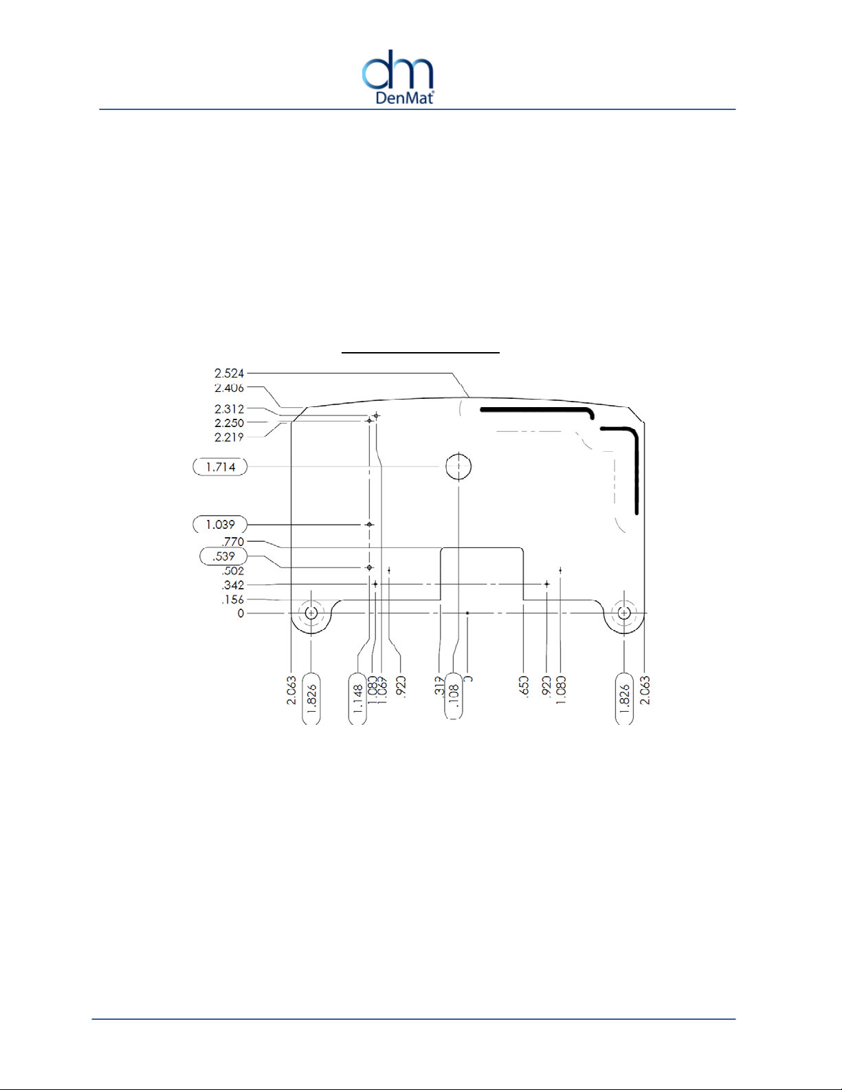
a. Mechanical Specifications
TOP VIEW DIMENSIONS

ConfidentialandProprietaryInformation●DenMatHoldings,LLC●1017W.CentralAve.,Lompoc,CA93436‐2701●1‐800‐433‐6628●Page3
-
+
TOP VIEW COMPONENT LOCATIONS
2-PIN HEADER J5 ACCEPTS PCB TRACE ANTENNA LOCATIONS.
SWITCH CLOSURE INPUT KEEP CLEAR FOR BEST PERFORMANCE
DC POWER INPUT PADS 2 LED INDICATORS WITH LIGHT
FOR WIRE ATTACHMENT PIPES FOR STATUS DISPLAY

ConfidentialandProprietaryInformation●DenMatHoldings,LLC●1017W.CentralAve.,Lompoc,CA93436‐2701●1‐800‐433‐6628●Page4
BOTTOM VIEW
PCB TRACE ANTENNA LOCATIONS SWITCH FOR
KEEP CLEAR FOR BEST PERFORMANCE RECEIVER PAIRING
CLEAR AREA DESIGNATED FOR
OPTIONAL BATTERY PACK INSTALLATION

ConfidentialandProprietaryInformation●DenMatHoldings,LLC●1017W.CentralAve.,Lompoc,CA93436‐2701●1‐800‐433‐6628●Page5
b. Electrical Specifications
Operating voltage range: 3.1VDC to 4.7VDC
Operating current consumption: < 50mA (in active transmitting mode)
Recommended power source: 3 primary AA size Alkaline or Lithium cells,
1.5V each
(not included)
Recommended battery holder module: keystone Electronics 2464
(not included)
c. Switch Interface Specifications:
The 2-pin header, J5, has the following interface specifications:
Voltage sourced from this header: 3VDC nominal
Current sourced out of this header: 1mA maximum
Maximum switch resistance expected: 100 Ohms
Manufacturer and part number for J5 header: Molex 0022122024
or equivalent
Recommended mating connector: Molex 0022012027 housing
Molex 0008550102 contacts
or equivalent
d. Environmental Specifications
Operating temperature: 0ºC to +50ºC
Storage temperature: -20ºC to +70ºC
Relative Humidity: 10% - 95% RH non-condensing
e. RF Communications Specifications
The radio section of this module is categorized as an intentional transmitter within the
unlicensed 2.4GZ ISM band. The details of communications protocol are described in a
separate document which is available upon request from DenMat Holdings, LLC.
The possible frequencies of operation are:

ConfidentialandProprietaryInformation●DenMatHoldings,LLC●1017W.CentralAve.,Lompoc,CA93436‐2701●1‐800‐433‐6628●Page6
Channel # Frequency
[MHZ]
1 2403
2 2408
3 2413
4 2418
5 2423
6 2428
7 2433
8 2438
9 2443
10 2448
11 2453
12 2458
13 2463
14 2468
15 2473
There are 15 channels of normal operation and one channel specially assigned for
transmitter-receiver pairing purposes.
During the pairing process, both a new channel number and a new address are selected
by this Module and get communicated to the external receiver.
Each time it is paired with a receiver, the Module increases the frequency by 2 channels,
meaning 10MHZ increments. The change is always in the ascending order and wraps
around once the maximum normal operating channel number (channel 15) has been
exceeded. For example, if starting at channel 1, then the following are the order of
channel numbers every time pairing is performed:
1, 3, 5, 7, 9, 11, 13, 15, 2, 4, 6, 8, 10, 12, 14, 1, 3, ……

ConfidentialandProprietaryInformation●DenMatHoldings,LLC●1017W.CentralAve.,Lompoc,CA93436‐2701●1‐800‐433‐6628●Page7
III. OPERATING INSTRUCTIONS
a. Indicators:
There are 2 LED indicators on the top side of the Module. The left one, D13, indicates RF
transmission and pairing status while the right one, D15, indicates the power
supply/battery level status. Here are the indication types and what they mean:
LEFT SIDE LED (D13)
SYMBOL COLOR SOLID/FLASHING STATE
NONE SOLID OFF
EITHER OF THE FOLLOWING :
IN SLEEP MODE
IN AWAKE MODE BUT WITH NO
RF TRANSMISSIONS
BLUE FAST FLASHING
NORAML RF TRANSMISSIONS IN
PROGRESS
BLUE SLOW FLASHING
PAIRING RF TRASMISSIONS IN
PROGRESS
RIGHT SIDE LED (D15)
SYMBOL COLOR SOLID/FLASHING STATE
NONE SOLID OFF
IN SLEEP MODE AND BATTERY
LEVEL IS NOT LOW
GREEN SOLID ON
IN AWAKE MODE AND BATTERY
LEVEL IS HIGH
YELLOW SOLID ON IN AWAKE MODE AND BATTERY
LEVEL IS MEDIUM
RED FAST FLASHING
IN AWAKE MODE AND BATTERY
LEVEL IS LOW
RED SLOW FLASHING
IN SLEEP MODE AND BATTERY
LEVEL IS LOW

ConfidentialandProprietaryInformation●DenMatHoldings,LLC●1017W.CentralAve.,Lompoc,CA93436‐2701●1‐800‐433‐6628●Page8
b. Pairing With a Receiver:
i. The receiver (a separate unit not supplied with this module) must be put into
Pairing mode in order to start the pairing process. This means that it must be on
the particular pairing frequency and pairing address as specified by this Module.
ii. Then, the pairing button on this Module must be pressed continuously until the
left side indicator starts flashing in blue color in slow speed. This usually takes
about 1 second or longer.
iii. Once the indicator has started flashing in blue, release the button and the
Module will continually transmit Pairing packets for about 5 seconds. The pairing
mode packets contain the new wireless address and new channel for the
receiver to learn. At the end of the pairing mode, the Module will save the newly
assigned channel and address in its non-volatile memory and then automatically
goes to sleep mode.
c. Sleep and Wakeups:
The Module enters a low power sleep mode as soon as power is applied to it. In this
sleep mode the only time an indicator would be visible is when the power supply/battery
level is in the low range, in which case the left side LED slowly flashes in red color. Either
pressing the Pairing button or a switch closure at header J5 can wake up the unit as long
as the power supply/battery level is not in the depleted (below low level) range.
d. Transmitting and Idle Modes:
Once a switch closure has been detected at J5, the unit enters active mode and will start
transmitting normal packets. While transmitting, the left side LED flashes rapidly in blue
color. While in active mode, the right side LED displays the current state of the power
supply/battery level as described in previous sections. As soon as the switch closure is
no longer detected, the module transmits multiple STOP packets before entering idle
mode. It stays in Idle mode (still indicating supply/battery level) for up to 2 minutes before
entering sleep mode.
IV. REGULATORY REQUIREMENTS
a. Labeling
When fully integrated in to the final product, it is required by United States and Canada
regulatory agencies to have a label on the exterior of the final product with wording as
shown below:
“This device complies with Part 15 of the FCC Rules. Operation is subject to the
following two conditions: (1) this device may not cause harmful interference, and (2)
this device must accept any interference received, including interference that may
cause undesired operation.”

ConfidentialandProprietaryInformation●DenMatHoldings,LLC●1017W.CentralAve.,Lompoc,CA93436‐2701●1‐800‐433‐6628●Page9
In addition, the FCC and Industry Canada (IC) certificate numbers must appear on the
label as follows:
“Contains FCC ID: SYS-SOL, IC: 11076A-SOL ”
An example of such label is shown below:
For use in other countries, contact DenMat Holdings, LLC.
b. Information for the User:
FCC requires certain information to be provided in the final product User’s Manual. The
following text must appear in the manual:
This device complies with Part 15 of the FCC Rules. Operation is subject to the
following two conditions: (1) This device may not cause harmful interference, and
(2) This device must accept any interference received, including interference that
may cause undesired operation.
Le présent appareil est conforme aux CNR d'Industrie Canada applicables aux
appareils radio exempts de licence. L'exploitation est autorisée aux deux conditions
suivantes : (1) l'appareil nedoit pas produire de brouillage, et (2) l'utilisateur de
l'appareil doit accepter tout brouillage radioélectrique subi, même si le brouillage
est susceptible d'en compromettre le fonctionnement
This equipment has been tested and found to comply with the limits for Class B
Digital Device, pursuant to Part 15 of the FCC Rules. These limits are designed to
provide reasonable protection against harmful interference in a residential
installation. This equipment generates and can radiate radio frequency energy and,
if not installed and used in accordance with the instructions, may cause harmful
interference to radio communications. However, there is no guarantee that
interference will not occur in a particular installation. If this equipment does cause
harmful interference to radio or television reception, which can be determined by
turning the equipment off and on, the user is encouraged to try to correct the
interference by one or more of the following measures.
Reorient or relocate the receiving antenna
Increase the separation between the equipment and receiver
Connect the equipment into an outlet on a circuit different from that to which
the receiver is connected
Consult the dealer or an experienced radio/TV technician for help
YOUR COMPANY NAME Model: 033989500
CONTAINS FCC ID: SYS-SOL, IC: 11076A-SOL
This device complies with Part 15 of the FCC rules subject to the
following two conditions:
1) This device may not cause harmful interference.
2) This device must accept all interference received,
including interference that may cause undesired operation.

ConfidentialandProprietaryInformation●DenMatHoldings,LLC●1017W.CentralAve.,Lompoc,CA93436‐2701●1‐800‐433‐6628●Page10
Any changes or modifications not expressly approved by the party responsible for
compliance could void the user’s authority to operate the equipment.
"Les changements ou modificationsnonexpressémentapprouvés parlapartie
responsable delaconformitépourraient annulerl'autorité del'utilisateur à
utilisercetéquipement."
c. Per Industry Canada RSS rules:
This device complies with Health Canada’s Safety Code. The installer of this device
should ensure that RF radiation is not emitted in excess of the Health Canada’s
requirement. Information can be obtained at http://www.hc-sc.gc.ca/ewh-
sem/pubs/radiation/radio_guide-lignes_direct-eng.php
Cet appareil est conforme avec Santé Canada Code de sécurité 6. Le programme
d’installation de cet appareil doit s’assurer que les rayonnements RF n’est pas émis au-
delà de I’exigence de Santé Canada. Les informations peuvent être obtenues:
http://www.hc-sc.gc.ca/ewhsemt/pubs/radiation/radio_ guide-lignes_direct-eng.php
V. INSTALLATION NOTES
Follow these general installation guidelines when integrating the Module into the final
product:
1. For best transmission distance, do not shield the antenna side of the Module with
electrically conductive or magnetic materials.
2. The Module can be powered with a DC power supply as described in previous
sections. Alternatively, it can be powered using 3 primary cells of Alkaline or Lithium
type, each being of the nominal 1.5V.
3. Certification will be void if any circuitry on this Module is modified or tampered with.
Contact DenMat Holdings, LLC for all such information or for any other questions
regarding safe and legal installation of this device.
4. The product housing should be designed in such a way as to not allow liquid spillage
on this Module.
5. Components on this assembly are static sensitive. Handle using proper Electrostatic
Discharge (ESD) protective equipment.
VI. MAINTENANCE AND CARE
No periodic maintenance is required for this module.
Table of contents
Popular Control Unit manuals by other brands


TriangleTube
TriangleTube Prestige Trimax 175 installation instructions

CHENGDU VANTRON TECHNOLOGY
CHENGDU VANTRON TECHNOLOGY AP6255 user manual

Intermatic
Intermatic LC4500 Series Instructions for installing

Cameron
Cameron WHEATLEY 820 Series Installation, operation and maintenance manual

IDEATEC
IDEATEC POLARIS user guide

NXP Semiconductors
NXP Semiconductors A3M38SL039 manual