Den-Sin C-250E User manual
Introduction
C-250E R14 Page 1
1. Introduction
Congratulations on your purchase of the DEN-SIN High Pressure Cleaner.
Model: C-250E
Read this user manual before you start up your High Pressure Cleaner the first time.
This document or part of it may not be photocopied, or in any other way reproduced, or
translated to other languages without the prior written consent of DEN-SIN.
This machine is a High Pressure Cleaner producing water jet under high-pressure, which is
why severe injuries can occur if the safety precautions are not observed.
Therefore a full understanding of the contents of this instruction manual is required, in order
to prevent injuries to you, objects and persons nearby.
Safety
The following symbols are used in this manual to indicate procedures that if not followed,
may results in personal injuries or damage to equipment.
Version 14: Apr 2018
Revision History
Revision Rev.No.
Cha
nge pump no.
10
Manual updating
11
Manual update, removal of CE declaration.
12
Manual Content Updating. Cable P/N Update
13
Manual Content Updating.
14
WARNING
is used to alert the reader of procedures or
practice which if not followed correctly could result in personal
injuries.
WARNING
CAUTION
CAUTION
is used to alert the reader of procedures or
practice which if not followed correctly could result in damage
to machine or other equipment.
NOTE
is used to highlight important information that may
assist the reader carrying out the procedure or understanding the
text.
NOTE
Table of Contents
C-250E R14 Page 2
Table of contents
Table of contents....................................................................................................................... 2
1. Getting acquainted with your High Pressure Cleaner...................................................... 3
Fast and efficient cleaning...................................................................................................... 3
Specifications ......................................................................................................................... 3
Applications............................................................................................................................ 3
Unpacking .............................................................................................................................. 4
Machine Installation / Setup................................................................................................... 4
Machine Shut Down Procedure.............................................................................................. 6
Operations .............................................................................................................................. 7
2. Safety and protection information...................................................................................... 8
General safety & application guidelines ................................................................................ 8
Safety devices......................................................................................................................... 9
Important medical information............................................................................................. 10
WARNING.............................................................................................................................. 10
Safety precautions ................................................................................................................ 11
3. Maintenance and troubleshooting .................................................................................... 12
Maintenance Schedule.......................................................................................................... 12
Machine Prevention.............................................................................................................. 12
Troubleshooting.................................................................................................................... 13
4. Available accessories.......................................................................................................... 21
ID-plate................................................................................................................................. 21
Chassis assembly.................................................................................................................. 22
Chassis assembly spare-parts list ......................................................................................... 23
Machine Model..................................................................................................................... 23
Pump assembly spare-parts list ............................................................................................ 26
Un-loader valve assembly .................................................................................................... 28
Un-loader valve assembly spare-parts list............................................................................ 29
Repair kit Unloader valve..................................................................................................... 30
Safety valve assembly .......................................................................................................... 31
Safety valve assembly spare-parts list.................................................................................. 31
Lance Assembly (Standard) ................................................................................................. 32
Lance assembly spare-parts list............................................................................................ 32
Trigger gun assembly ........................................................................................................... 33
Trigger / gun & assembly spare-parts list E250 ................................................................... 33
Repair Kit Trigger Gun ........................................................................................................ 33
Electrical Box ....................................................................................................................... 34
Wiring diagrams ................................................................................................................... 35
5. Warranty............................................................................................................................. 36
The information contained in this user guide is subject to change without
notice.
NOTE

1. Getting acquainted with your High Pressure Cleaner
C-250E R14 Page 3
1. Getting acquainted with your High Pressure Cleaner
Fast and efficient cleaning
The DEN-SIN High Pressure Cleaners in the C-250E series enables you to get more cleaning
done in less time.
This series of DEN-SIN High Pressure Cleaners offers you high performance yet a compact
design. The compact design enables the machines to be agile within inconvenient places even
at staircases, and the high performance gives you the opportunity to solve an array of cleaning
tasks. The High Pressure Cleaners in this series are designed for industrial/ Trucking &
Livestock transport companies/ Agriculture & Farming/ Shipping & Bulk carrying barges
and offshore use as well as for cleaning contractors. All pump parts, fittings and pipes in
contact with water are made of non-corrosive materials. Together with the ceramic pistons,
long life seals and stainless steel valves, it ensures long life and high durability.
Specifications
Model Motor Motor
Speed
Working
Pressure
Flow Capacity Power Supply
Dimensions
x W x H
Weight
Hp
kW
rpm
psi
Bar
gpm
/min
Voltage
mm
kg
C-250E
(700995661)
10 7.5
1500 3625 250 2.6 15
380-400Vac
( 5 0 H z ) 930x585x940
95
C-250E
(700995655)
10 7.5
1800 3625 250 2.6 15
4 4 0 V a c
( 6 0 H z ) 930x585x940
95
Applications
These heavy-duty High Pressure Cleaners are capable of removing any kind of dirt:
Algae off concrete constructions
Paint and graffiti off walls
Dust, dirt, soil & mud off floors
Oil & grease off engines and other mechanical parts
Dirt and salt deposits off ship decks
And with the option for use of accessories even many more jobs are to be dealt with:
Sand-blasting
Drain-cleaning
Dispensing of soaps and chemicals
Sludge pumping
Extra long lances for hard to reach places
Floor cleaning equipment
Rotary brushes
This machine is only to be used for the purposes it is designed for. Any other use shall be
considered improper and therefore potentially dangerous. The manufacturer is not to be held
responsible for any damages caused by improper use.
CAUTION
1. Getting acquainted with your High Pressure Cleaner
C-250E R14 Page 4
Unpacking
Remove the High Pressure Cleaner and its accessories from the packing material. For
transport and packing reasons some accessories may be supplied disassembled.
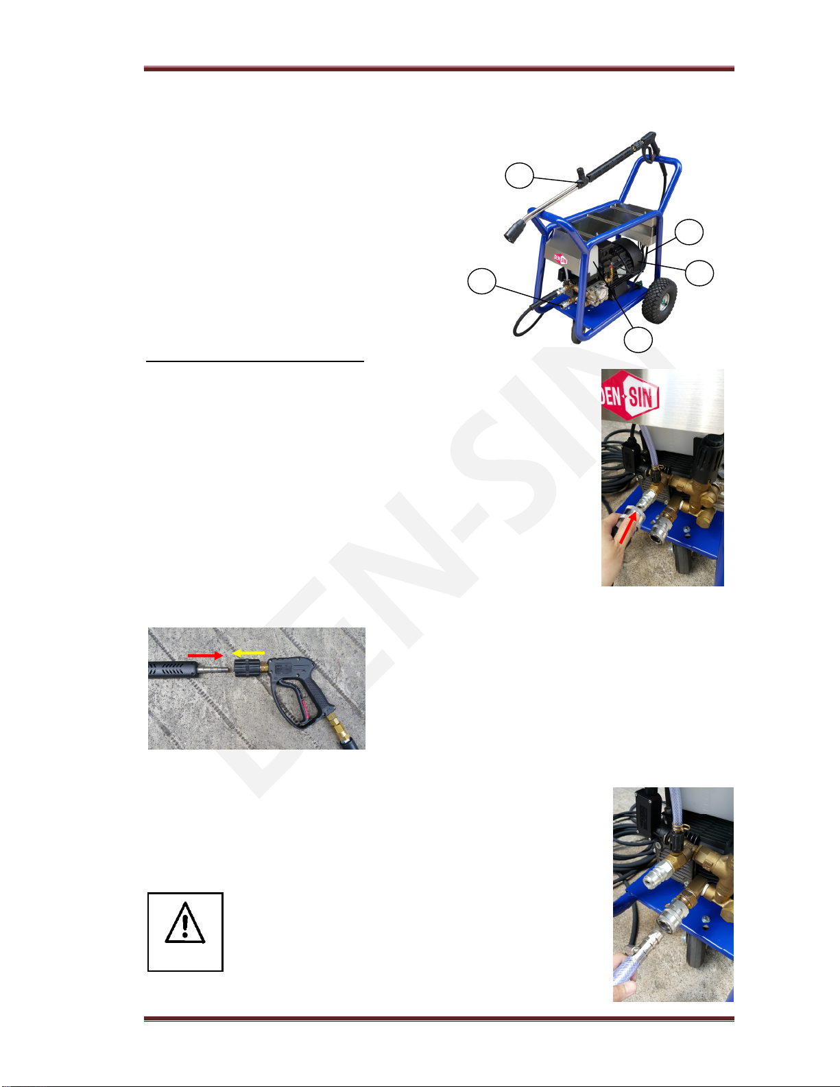
Make sure all components are present:
1) High-pressure machine itself
2) Chemical Tank
3) Electrical cord (attached)
4) High pressure hose with Lance Trigger
5) Water inlet male hose coupling
Machine Installation / Setup
Mount the high-pressure hose on to the High Pressure Cleaner by
pulling back the retainer on the high-pressure hose coupling, while
sliding it onto the male outlet of the unloader till a click sound could be
heard.
Assemble the double barrel spray-lance. To mount the
assembled spray-lance on to the Spray-gun trigger, pull
forward the front of the Spray-gun trigger (A) while
sliding in the male swivel coupling part of the spray-
lance. (B)
Prepare the water supply for the High Pressure Cleaner by attaching a
hose to the supplied low pressure inlet male-coupling. Connect the other
end of the water supply hose to a potable water tap. Turn on tap.
Connect to the public mains water supply in accordance to
regulations.
Notice
(A)
(B)
1
2
3
4
5
1. Getting acquainted with your High Pressure Cleaner
C-250E R14 Page 5
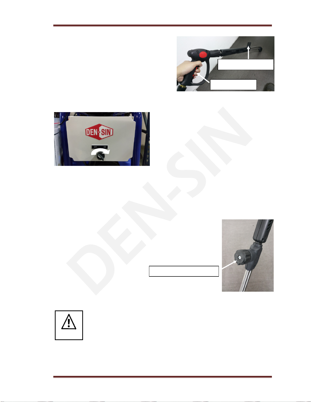
The high pressure cleaner is now ready for
operation. The spray-gun lance is affected by a
recoil force during operation – therefore keep a
firm grip with both hands on the Spray-gun handle
and the lance. Press the trigger and tighten pressure
regulating knob to achieve maximum pressure for
effective cleaning.
Put the power-plug into a main power supply
socket. Turn on the power of the High Pressure
Cleaner by turning the knob clockwise to the ON
position.
The high pressure cleaner is now ready for operation. The contractor lance is affected by a
recoil force during operation – therefore keep a firm grip with both hands on the contractor
lance. Open ball valve and tighten the needle valve to achieve maximum pressure for effective
cleaning.
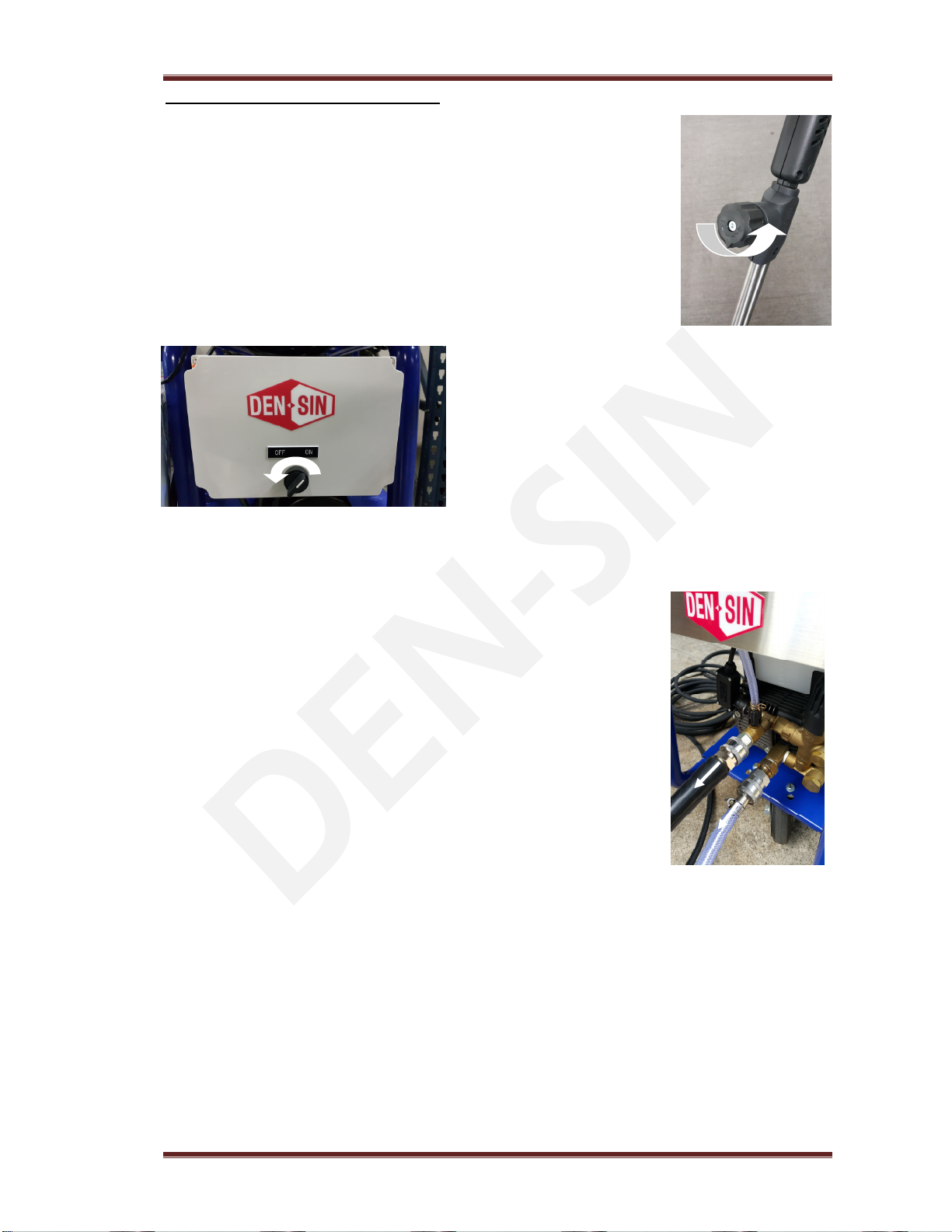
The pressure can be regulated by turning the knob on the spray-gun
lance. Tighten knob for maximum pressure and loosen for low
pressure washing. When using chemical injector, pressure must be
adjusted to low.
Make sure your local power supply specifications are in accordance with the
motors requirement. Refer to the ID-plate on the machine. Do NOT run the
High Pressure Cleaner without sufficient potable water supply as it can cause
cavitation and serious damage to internal pump parts. Do not let the machine
recycle the water (running with Spray-gun trigger not activated) for more than
a minute. This can cause serious damage to the seals.
CAUTION
D
epress Trigger
Knob fully tighten
Pressure Regulating Knob
1. Getting acquainted with your High Pressure Cleaner
C-250E R14 Page 6
Machine Shut Down Procedure
Release trigger and lower down the pressure by loosening the knob on
the lance.
Turn off the High Pressure Cleaner by turning the
knob anti-clockwise to the OFF position. Switch off
the main power supply
Once machine stop, open the ball valve and needle valve to release trap pressure in the pump
and hose line. Make sure lance is pointing downwards when doing this as pressure could
cause injury.
Once pressure is release, turn off water supply and disconnect inlet
and outlet hose from machine. Dry the machine and store it.
1. Getting acquainted with your High Pressure Cleaner
C-250E R14 Page 7
Operations
To prevent accidents from happening, ensure the safety of the person(s) who
uses the equipment and to protect bystanders and nearby placed inventory or
machinery, a few safety precautions needs attention.
1) Treat the machine as a high-speed cutting tool.
2) Anyone under the age of 18 is NOT allowed to use the machine.
3) Always use a proper plug and socket specially designed with ground to earth wiring.
4) Only connect to an installation with earth wiring. A certified electrician shall make the
installation. It is strongly recommended that the electric supply to the machine include a
Residual Current Device/GFCI.
5) Always keep the High Pressure Cleaner and its accessories in good working condition.
Check the machine for defects, especially the insulation on the electric cable. Do NOT
start up the machine if there is any defect. Have the machine serviced.
6) When using the High Pressure Cleaner and its accessories, eye protection must be worn
to protect against repelling or ricocheting matters causing eye damage.
7) Suitable clothing and footwear must be worn while using the equipment to protect the
operator. Do not try to clean clothes or footwear with the machine.
8) Precautions must be made to keep bystanders away from the working range.
9) Do NOT spray-clean on yourself, others or live animals. The
high-pressure beams are capable of making severe injuries.
10) Do NOT spray at electrical equipment OR the machine itself.
11) While repairing or servicing the equipment and its accessories always make sure the
machine is turned off and disconnected from the main power supply.
12) Only allow instructed personnel to operate the machine.
13) Activating the trigger/gun can cause backward force therefore always hold spray lance
with both hands.
14) When pausing during operation, turned off the main switch of the machine.
15) Only use high-pressure hoses, connections and nozzles specified by DEN-SIN.
16) IMPORTANT – Do not use the machine in a possible explosive environment in
accordance with EN-50014.
WARNING

2. Safety and Protection information
C-250E R14 Page 8
2. Safety and protection information
General safety & application guidelines
1) It is not allowed to clean asbestos containing surfaces with high-pressure, unless using
special equipment.
2) Persons under the influence of alcohol, drugs or medicine should not operate the machine.
3) Do not touch plug and socket with wet hands.
4) This machine has been constructed for use with Nilfisk-ALTO detergents. The use of
other detergents or chemicals may cause problems as to the operation and the safety.
5) When using detergents the instructions should always be strictly observed.
6) Always flush the machine with clean water after use of chemical/detergents.
7) Always unplug power supply when cleaning and maintaining the machine.
8) Do not use the machine if important parts are damaged – i.e. safety devices, high-pressure
hoses, spray handle.
9) The user is obliged to observe all national working environment and working safety
regulations concerning “operation of high-pressure washers”.
10) It is not allowed to connect this machine directly to a potable water supply.
11) If the machine is to be connected to potable water supply it is strictly necessary to fit the
machine with a water break tank, in accordance with EN1717.
2. Safety and Protection information
C-250E R14 Page 9
Safety devices
The machine is equipped with the following safety devices:
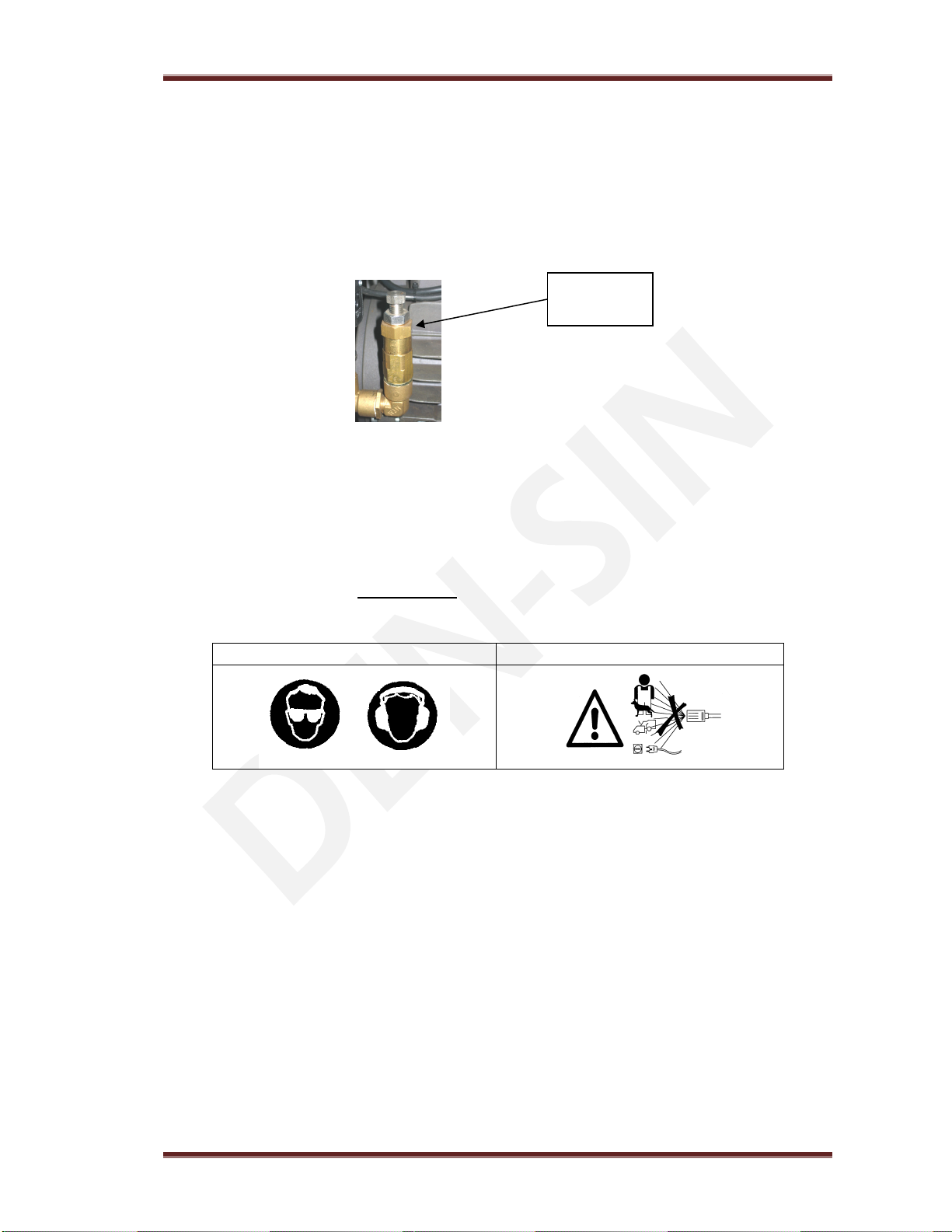
1) Safety Valve protects the machine from over pressure. Once the pressure is set higher than
260~280Bar, the safety valve will open and water will leak out. These indicate, unloader
was adjusted too high. Adjust the unloader back to its rated pressure 250Bar.
4)
Automatic Start / Stop:
These Pressure Washer comes with Automatic Start/ Stop
function for extended life span of the pump. If the machine is running for more than (1.5
minutes) without trigger/ gun being activated then it will shut down automatically. To restart
the machine, simply press the trigger/ gun and the machine will start automatically.
The timer is preset to 1.5 minutes - do NOT change the setting.
DO DON’T
Safety
Valve
2. Safety and Protection information
C-250E R14 Page 10
Important medical information
Immediate hospital attention should be given personnel who sustain equipment related injuries
while operating the system. In such cases, it is vital that medical personnel be apprised of all
facts relevant to such injuries. Therefore, all operating personnel should be provided with
waterproof emergency medical alert tags or cards, describing the nature of their work and the
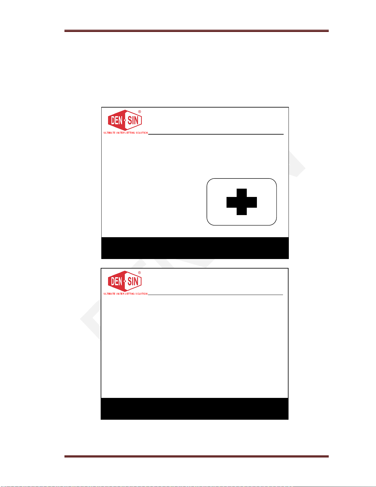
possibility of injury inherent in the use of water jetting equipment. The below example of a
standard card can be photo copied, laminated and used as medical alert tag.
WARNING
DEN-SIN - a division of Nilfisk Pte Ltd.
05 Tuas Ave 2 Singapore 639445
Tel: +65 6268 1006 Fax: +65 62684916
Obtain medical treatment
immediately for ANY high-pressure
water-jet injuries.
Inform the doctor of the cause of the
injury.
Show this card to the doctor.
This card is to be carried by
personnel working with high-
pressure water jetting equipment.
IMPORTANT
MEDICAL INFORMATION
MEDICAL ALERT
NOTE TO PHYSICIAN
This patient may be suffering from a water jet
injury. Evaluation and management should
parallel that of a gunshot injury. The external
manifestations of the injury cannot be used to
predict the extent of internal damage. Initial
management should include stabilization and
a thorough neurovascular examination.
X-rays can be used to access subcutaneous air
and foreign bodies distant from the site of
injury. Injuries to the extremities can involve
extensive nerve, muscle, vessel damage, as
well as cause a distal compartment syndrome.
Injuries to the torso can involve internal
organ damage. Surgical consultation should
be obtained. Aggressive irrigation and
debridement is recommended.
Surgical decompression and exploration may
also be necessary. Angiographic irrigation
studies are recommended pre-operatively if
arterial injury is suspected. Bandages with a
hygroscopic solution (MgSO
4
) and
hyperbaric oxygen treatment have been used
as adjunctive therapy to decrease pain, edema
and subcutaneous emphysema.
Unusual infections with uncommon
organisms in immune competent patients
have been seen; the source of the water is
important in deciding on initial, empiric
antibiotic treatment, and broad spectrum
intravenous antibiotics should be
administered.
Cultures should be obtained
DEN-SIN - a division of Nilfisk Pte Ltd.
05 Tuas Ave 2 Singapore 639445
Tel: +65 6268 1006 Fax: +65 62684916
2. Safety and Protection information
C-250E R14 Page 11
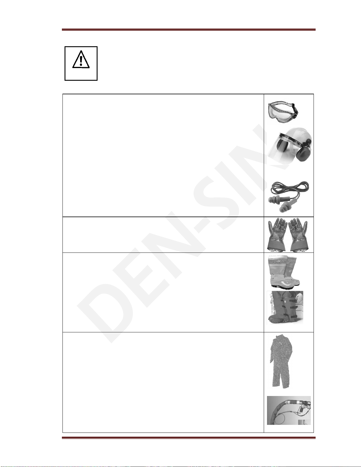
Safety precautions
The following protective clothing and devices should be worn both by
personnel operating the water blaster system and equipment and by those
working nearby:
Please contact DENSIN for various type of safety equipment available
Eye protection- Operators must wear visors and goggles to guard
against spray and flying debris. A combination of both goggles and visor
is advisable. And will protect the eyes and the face during both water-
blasting as well as abrasive water-blasting
Head protection- Helmets must be worn at all time by personnel within
the work area.
Helmet material must be able to withstand mechanical shock without
fracturing.
Hearing protection- Operators and other personnel exposed to noise
levels of more than 90-dBa for more than 1 hour must wear suitable ear
protection. Ear plugs or ear muffs are usually sufficient.
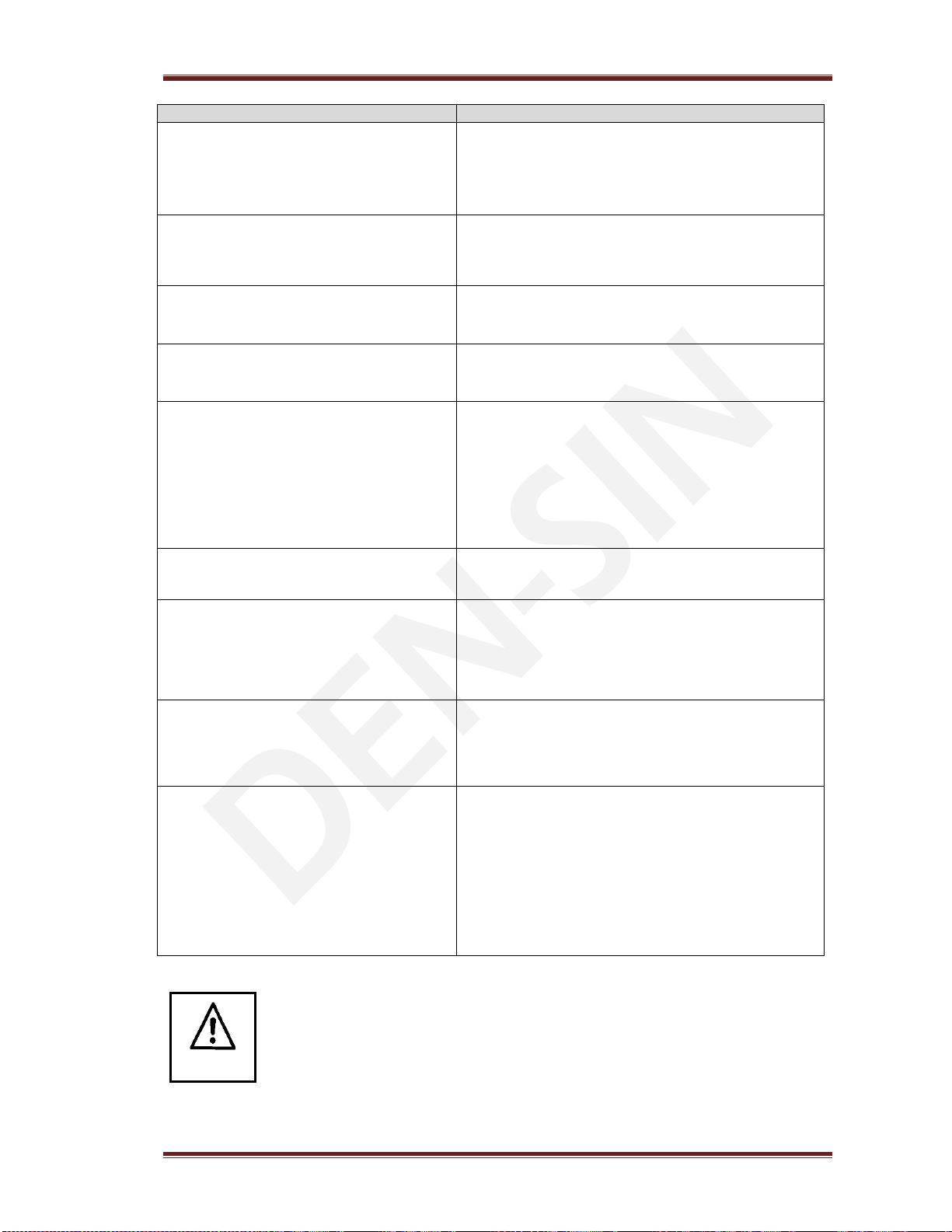
Hand protection- Shear proof gloves must be worn by the operator at
all times. A glove combination of a cloth inner lining and a water tight
outer layer is preferred.
Foot protection- Safety footwear with steel toecaps must be worn. Basic
safety footwear must also be equipped with metatarsal guards to protect
the instep. Safety boots are available in other designs than the
illustration.
Gaiters- This is an additional layer of protection to the user foot that are
not protected by the steel top cap. It is intended to be worn outside of the
user’s regular protective boots. Five clips ensure that gaiters securely
stay in place. The entire area is protected. Very comfortable and light to
wear.
Body protection- Waterproof garments protect the operator only from
spray and flying debris. They do NOT deflect direct jet impact.
Therefore, an operator must take care never to point a water-jet either at
themselves or other personnel.
Hose protection- Protect user from high pressure water injuries incase
hose connection is loose.
WARNING

3. Maintenance and Troubleshooting
C-250E R14 Page 12
3. Maintenance and troubleshooting
Maintenance Schedule
Regular Service
Period as
indicated
Each
use
1
st
50hrs
Every
month /
Every
500hrs
When
needed
Procedure / Remarks
Check pump oil
level
•Top up if necessary.
Change pump oil
Recommended Oil :
SAE 15W40
Usage :
Approx. 0.4kg of
oil
Renewal of oil:
•Turn off High Pressure Cleaner.
•Loosen bolt(Hex) at bottom of pump housing.
•Drain oil into a waste oil-tray.
•Tighten bolt(Hex)
•Add oil through pump inlet on top of the pump
until the red point of the oil control glass has
been reached.
Notice:
Do not dispose of used oil in drain.
Cleaning of
machine
•Use damp cloth to wipe the cabinet and handle
bar.
Notice:
Do not use detergent cleaning chemicals
Cleaning of
motor fan
(
to ensure sufficient
airflow )
•Clean the motor fan cover.
•Clean the motor fan blade.
Do NOT operate the machine with damaged or
removed fan cover.
Machine Prevention
Do
Don
’
t
Action
Cause
Spray directly onto the machine with high
pressure water
Electrical shock may occurs
Operate the machine with damaged or removed
fan cover
Motor will be overheated and malfunction
Operate/keep machine with frost built up
Flush pump with antifreeze fluids before use.
Check hose and cord are not vehicle run over
by heavy or
squeezed
in door opening
May cause machine not function properly.
Check electrical cord and high pressure hose
for wear and cracks
To prevent electrical shock and safety to the user
Ensure coupling parts free of dirt to ensure
long life of O-ring seals preventing water leaks.
Extend life span of the pump seals and
maintaining correct pressure.
3. Maintenance and Troubleshooting
C-250E R14 Page 13
Troubleshooting
Symptom
Rectification
Main switch is turned on the High Pressure
Cleaner will not run.
•Check power supply connection for faulty components.
•Make sure the socket is inserted correctly
•Check if fuse is blown, replace if necessary.
Motor is humming & Pump does not give
pressure or low pressure
•
Voltage is too low as compare to specification.(Check main voltage)
•Motor phase is missing (For 3 phase application).
Check the connection box voltage with a meter
•High-pressure pump is blocked
Pump pressure drops and the High Pressure
Cleaner works irregularly
•
Strain filter is clogged.
•Water supply from the tap is insufficient.
•Clean the strain water filter
Pump continuously stops and starts, when the
spray-gun trigger is activated.
•
The high pressure nozzle is partly clogged.
Turn off the High Pressure Cleaner, dismantle the high-pressure nozzle
and remove the extraneous matter. Replace if damaged
High pressure cleaner does not reach the proper
working pressure when the spray-gun handle is
activated
•
The high-pressure nozzle is clogged.
•Dirt in the by-pass valve.
•The pump sucks air.
•Turn off the High Pressure Cleaner. Clean the nozzle.
•Inspect the low pressure supply, while spray-gun trigger is activated,
ON the machine on again.
•Repeat the procedure again; now with the trigger released. If the
problem still occurs, by-pass valve should be dismantled and the
extraneous matter removed.
High Pressure Cleaner only works with
approximately 2/3 of the maximum pressure,
a
nd the high
-
pressure hose is vibrating.
•
Valves are dirty
•Remove the dirt and check to ensure the valve flaps are movable and
fit tightly.
Noisiness
•
The pump sucks air.
•One or more valve springs are broken or down.
•Extraneous matter in the valves.
•Crankcase or motor bearings worn out.
•Inspect the low-pressure supply. Replace springs.
•Clean the valves. Replace the bearings.
Water in the oil
•
The O-ring casing is worn out.
•High moisture in the air (condensing inside the crankcase)
•The seals are completely worn out.
•Check or replace the O-ring.
•Renewal of the crankcase oil more often.
•
Replace the seals.
The High Pressure Cleaner does not suck
chemicals
•
The chemical container is empty.
•The High Pressure Cleaner has not been set to low-pressure (on the
double barrel lance cock).
•The low-pressure nozzle is clogged, or partly clogged.
•The non-return valve of the chemical injector is stuck.
•Ensure the chemical container contains sufficient fluid for proper
suction.
•Set the spray-lance to low pressure by turning the cock on the lance
counterclockwise.
•Clean or replace the low-pressure nozzle.
•Clean, correct or replace the non-return valve of the chemical injector.
For any further inconveniences, not mentioned in this user guide or any
damages of the machine, we strongly suggest you to make contact with your
dealer for the repair or possible replacement of any original spare-parts.
NOTE

3. Maintenance and Troubleshooting
C-250E R14 Page 14
Pump Maintenance Instructions
Detach the high pressure hose, dump back hose, inlet hose, safety valve, and parts on the
pump head before serving the pump.
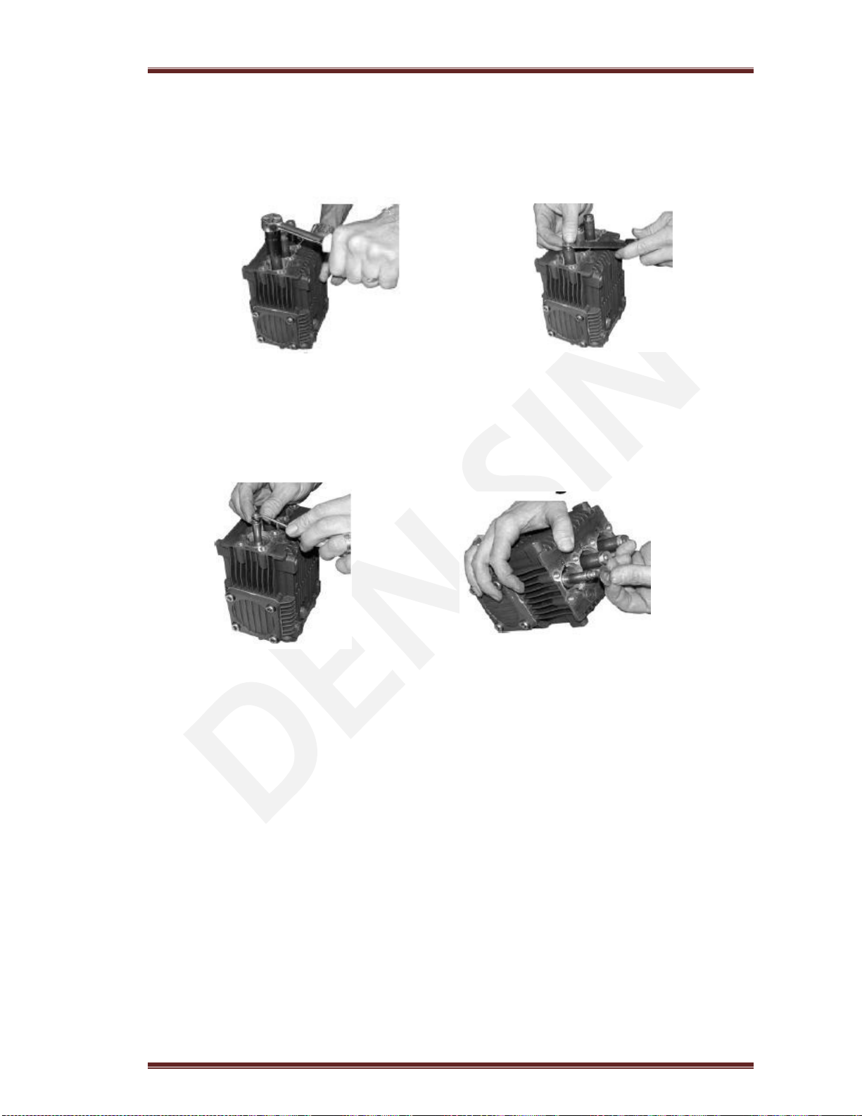
Valve Removal:
1. Remove the valve cap.
2. Inspect the valve cap O-ring for any damage, replace if necessary. (See Fig. 1)
3. Use the needle nose pliers to remove the valve. (See Fig. 2)
4. Use a small probe to move the poppet up and down to assure that the valve is functioning
properly and that no debris is stuck in the valve. (See Fig.3)
5. Using the mechanics pick remove the valve seat O-ring and inspect for any damage, replace
if necessary. (See Fig. 4)
Fig.1 Fig. 2
Fig.3 Fig.4

3. Maintenance and Troubleshooting
C-250E R14 Page 15
Valve Assembly:
1. Install the valve seat O-ring squarely into the bottom of the manifold. (See Fig.5)
2. Insert the valve assembly squarely into the port pushing it into the O-ring. (See Fig.6)
3. Install the valve cap and torque to the proper specification. (See Fig.7)
Fig.5 Fig.6
Fig.7

3. Maintenance and Troubleshooting
C-250E R14 Page 16
Servicing the Packing / Seals
Disassembly:
1. First remove the eight 6mm head bolts. (See Fig. 8)
2. Place the screwdrivers as shown between the head and crankcase of the pump, lifting one
up and the other down. The head should start to lift off of the plungers. (See Fig.9)
3. When you remove the head you may notice that some of the water seals have stayed on the
plungers and some in the head. (See Fig.10) To remove the seals from the plungers simple
turn the assemblies and pull off.
4. If the seal assemblies are in the head use the reversible pliers to grab the seal retainer on the
inside bore (NOTE: Use a rag so you do not mar the piston guide area), twist the retainer in
either direction. (See Fig.11)
5. With your fingers pull the high pressure seal and head ring out of the head.(See Fig.12)
6. The low-pressure seal is located in the brass seal retainer. Using the mechanics pick go in
between the seal and retainer, twist and pull, the seal will come out of the gland.
(See Fig.13 & 14)
7. Remove the seal retainer O-ring with the mechanics pick. (See Fig.15)
Fig.8 Fig.9
Fig.10 Fig.11
Fig.12 Fig.13
Fig.14 Fig.15

3. Maintenance and Troubleshooting
C-250E R14 Page 17
Assembly:
1. Install the plastic head ring into the head (the flat side is on the bottom). (See Fig. 16)
2. Install the high-pressure seal. Place the seal so the open “V” portion is toward the head ring.
You need to place the seal at an angle and pull and push to work the seal into position with
your fingers (do not use and tools you may damage the seal). Make sure the seal is totally
seated against the head ring. (See Fig. 17)
3. Installing the low-pressure seal. You want the open side of the seal to be pointed toward the
water side of the head (toward the high-pressure seal) and the flat side toward the drive end
of the pump.
Place the seal into the gland at an angle, with your finger push the exposed side of the seal
towards the center and work the seal (See Fig. 18, 19) into position. After the seal is in the
gland you can work it into it proper position.
4. Install the retainer O-ring. (See Fig. 20)
5. Squarely seat the retainer into the head and push with even pressure until it snaps into
position. (See Fig.21)
Fig.16 Fig.17
Fig.18 Fig.19
Fig.20 Fig.21
3. Maintenance and Troubleshooting
C-250E R14 Page 18
Servicing the Plungers
Disassembly :
1. Remove the plunger retainer nut. (See Fig. 22)
2. Insert the gasket scraper between the copper washer and plunger to remove the washer.
(See Fig. 23)
3. Twist and pull the plunger off the plunger rod.
4. Remove the plunger rod O-ring seal and split back-up ring with the mechanics pick. (See
Fig. 24)
5. Remove brass slinger. At this point clean any thread locker that is left on the plunger rod
and retaining nut threads. (See Fig. 25)
Fig.22 Fig.23
Fig.24 Fig.25

3. Maintenance and Troubleshooting
C-250E R14 Page 19
Assembly:
1) Install the slinger washer. (See Fig.26)
2. Install the plunger rod O-ring and split back-up ring. Place a light film of oil on the O-
ring and back-up ring. (See Fig. 27)
3. Install the plunger by pushing straight down and twisting slightly in either direction (See
Fig. 28)
4. Install the small copper washer on top of the plunger and place a small quantity of thread
sealant in the thread. Install the plunger nut and tighten to the required torque. (See Fig. 29
& 30)
Fig.26
Fig.27 Fig.28
Fig.29 Fig.30

3. Maintenance and Troubleshooting
C-250E R14 Page 20
Pump head to drive end Installation
1. Turn the crankshaft to align the plungers as shown. (See Fig.31)
2. Place the head evenly onto the plungers and push it until it makes contact with the drive end
of the pump. (See Fig.32)
3. Torque the head bolt as shown in the tightening sequence diagram. (See Fig. 33 & 34)
Fig.31
Fig.32
Fig.33 Fig.34
D es c riptio ns H e ad (F ig .3 4) P is t on N u t V a lve C ap
In.lbs 133 10 6 4 42
K g .m /N .m 1 5 1 2 5 0
Table of contents
Other Den-Sin Pressure Washer manuals


Popular Pressure Washer manuals by other brands


Snapper
Snapper SP3400 Quick Start Up/Shutdown Guide

Elektro Maschinen
Elektro Maschinen HDEm 2550 user manual

Murray
Murray 2000 PSI Series quick start guide

Xstream
Xstream PE-5024HWEBGEN Operation manual

Kärcher
Kärcher K2.01 operating instructions

Shark
Shark HPB HPB-3520 Operating instructions and parts manual