Den-Sin C-110E Guide

USER GUIDE & SPARE PARTS MANUAL
C-110-150-170-200E
ELECTRICAL POWERED
HEAVY DUTY COLD WATER
HIGH PRESSURE CLEANER
www.densin.com

C-110-170-200E R11 Page 1
Introductions
Congratulations on your purchase of the: DEN-SIN High Pressure Cleaner
Model: C-110E, C-150E, C-170E & C-200E
Read this user manual before you start up your High Pressure Cleaner the first time.
This document or part of it may not be photocopied, or in any other way reproduced, or
translated to other languages without the prior written consent of DEN-SIN.
This machine is a High Pressure Cleaner producing water jet under high-pressure, which is
why severe injuries can occur if the safety precautions are not observed.
Therefore a full understanding of the contents of this instruction manual is required, in order
to prevent injuries to you, objects and persons nearby.
Safety
The following symbols are used in this manual to indicate procedures that if not followed,
may results in personal injuries or damage to equipment.
Version 11: Nov 2017
Revision Rev No.
Repair Kit for Unloader Valve 6
Repair Kit updating & Accumulator for 110V machine only 7
Updating of Manual with new configuration components
Revise component P/N for Accumulator
8
Manual Update, Removal of CE declaration.
9
Manual Content Updating. Cable P/N update 10
WARNING
is used to alert the reader of procedures or
practice which if not followed correctly could result in personal
injuries.
WARNING
CAUTION
CAUTION
is used to alert the reader of procedures or
practice which if not followed correctly could result in damage
to machine or other equipment.
NOTE
is used to highlight important information that may
assist the reader carrying out the procedure or understanding the
text.
NOTE
NOTE
The information contained in this user guide is subject to
change without notice.

C-110-170-200E R11 Page 2
Table of contents
Introductions ............................................................................................................. 1
Table of contents .................................................................................................................... 2
1. Getting acquainted with your High Pressure Cleaner........................................ 3
Fast and efficient cleaning...................................................................................................... 3
Specifications ......................................................................................................................... 3
Applications............................................................................................................................ 3
Unpacking .............................................................................................................................. 4
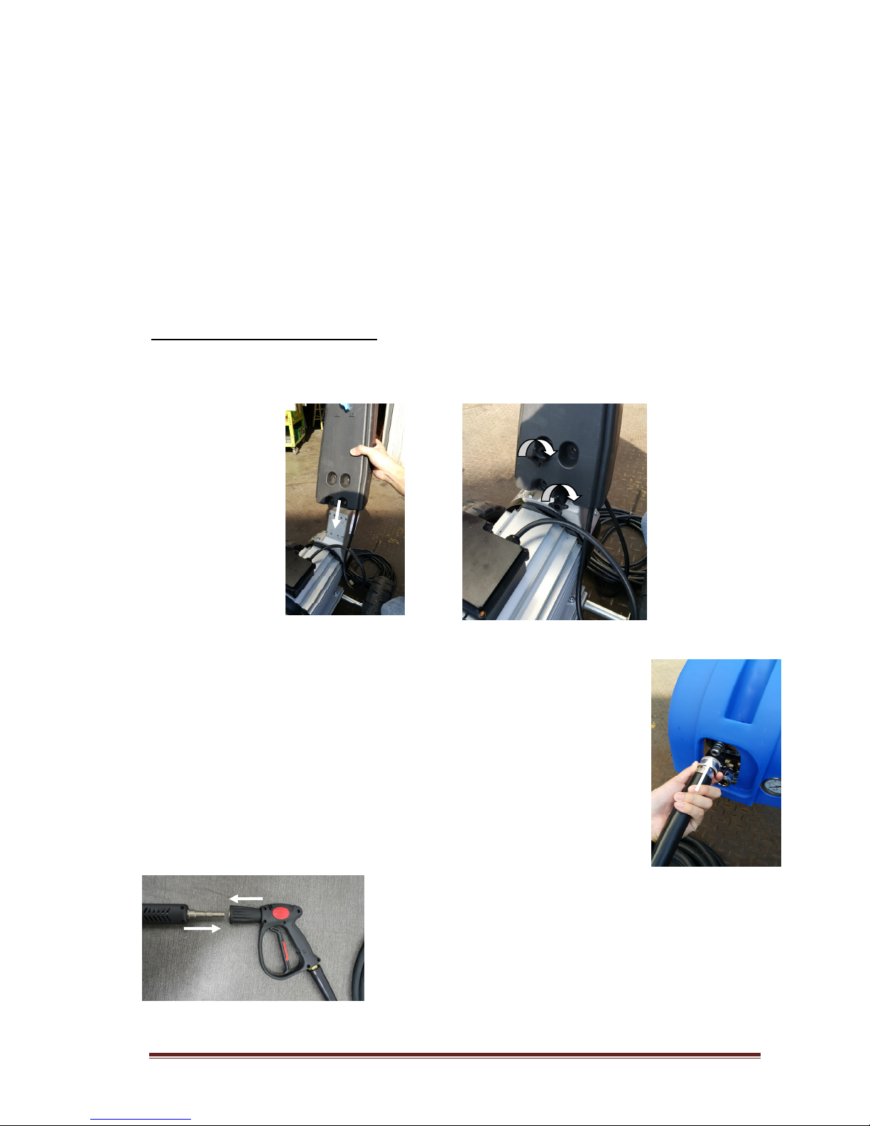
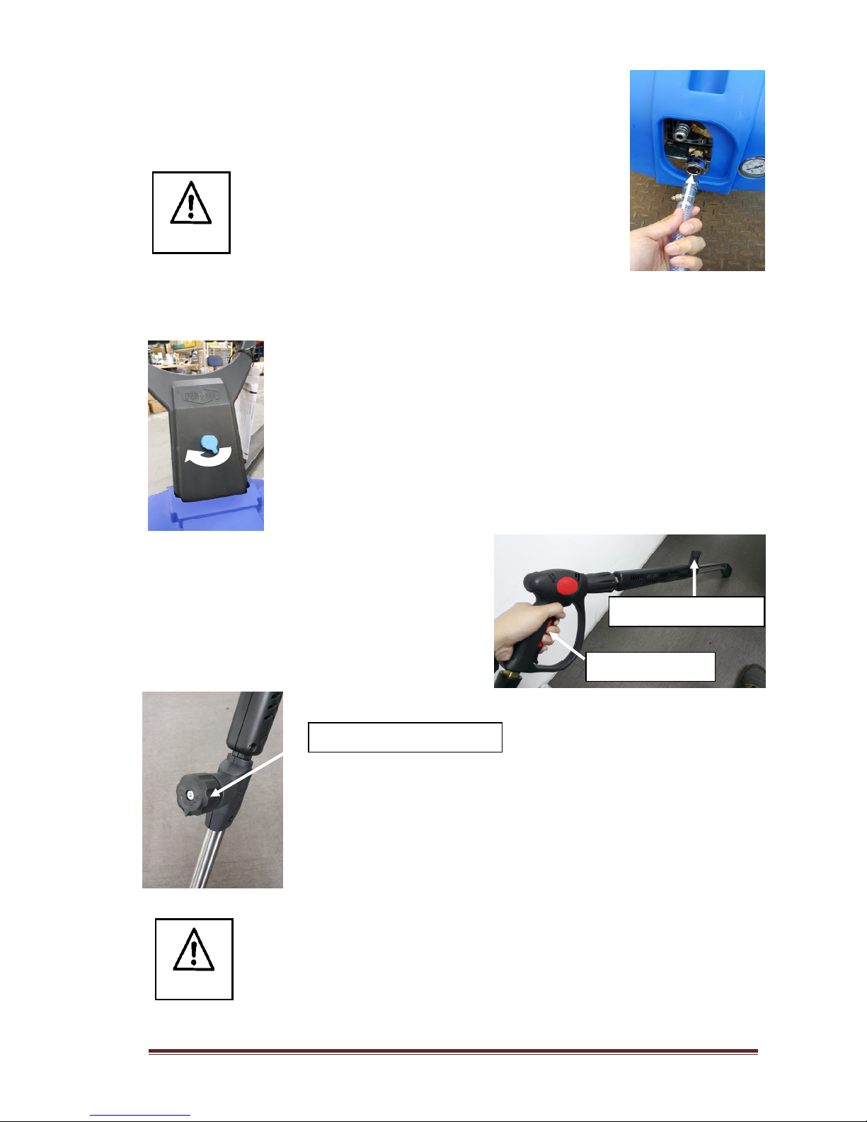
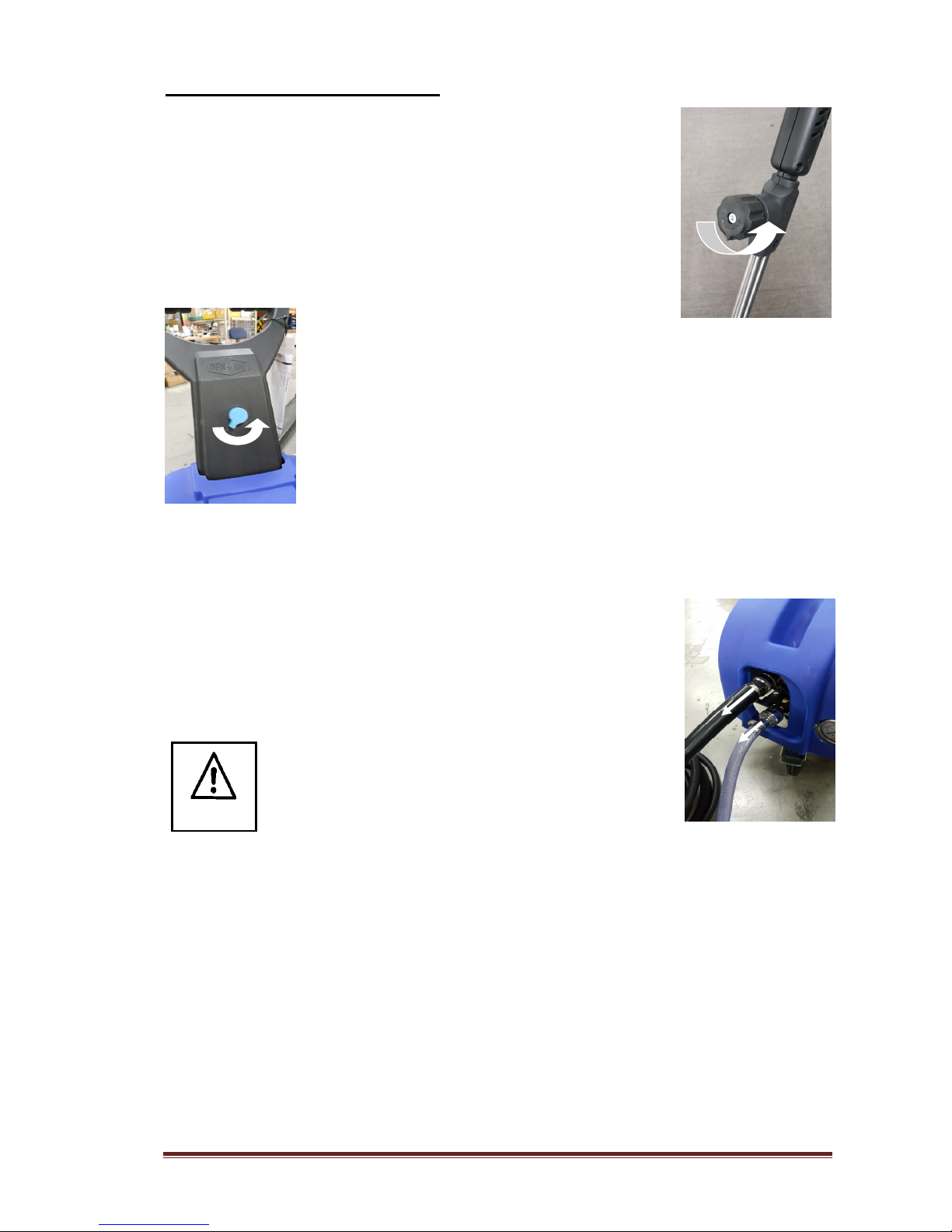
Machine Installation / Setup................................................................................................... 4
Machine Shut Down Procedure.............................................................................................. 6
Operations .............................................................................................................................. 6
2. Safety and protection information ....................................................................... 7
General safety & application guidelines ................................................................................ 7
Safety devices......................................................................................................................... 8
Safety precautions .................................................................................................................. 9
3. Maintenance and troubleshooting ..................................................................... 11
Maintenance Schedule.......................................................................................................... 11
Machine Prevention.............................................................................................................. 12
Troubleshooting.................................................................................................................... 13
Service instructions .............................................................................................................. 14
4. Accessories and Spare Parts............................................................................. 18
ID-plate................................................................................................................................. 18
Chassis assembly.................................................................................................................. 19
Chassis assembly spare-parts list ......................................................................................... 20
Pump assembly..................................................................................................................... 22
Pump assembly spare-parts list ............................................................................................ 23
Pump spare-parts kit............................................................................................................. 24
Un-loader valve assembly .................................................................................................... 25
Unloader valve assembly spare-parts list ............................................................................. 25
Repair kit Unloader valve..................................................................................................... 27
Safety valve assembly C-200E............................................................................................. 27
Safety valve assembly spare-parts list C-200E .................................................................... 27
Start-up accumulator assembly C-110E (110V 60Hz only)................................................. 28
Start-up accumulator assembly spare-parts list C-110E....................................................... 28
Lance assembly 1 (Standard) ............................................................................................... 29
Lance assembly spare-parts list............................................................................................ 29
Optional Lance assembly 2 (Optional)................................................................................. 30
Lance assembly spare-parts list............................................................................................ 30
Complete HP hose assembly ................................................................................................ 31
Complete HP hose w/ Trigger gun ....................................................................................... 31
Trigger gun assembly ........................................................................................................... 32
Trigger gun assembly spare-parts list................................................................................... 32
5. Wiring Diagram.................................................................................................... 34
Wiring diagrams (Non-Auto Start Stop) .............................................................................. 34
Wiring diagrams (Auto Start Stop Single phase) ................................................................. 35
Wiring diagrams (Auto Start Stop 3 phase) ......................................................................... 36
Wiring diagrams (Auto Start Stop 3 phase 220V) ............................................................... 37
6. Warranty............................................................................................................... 38

C-110-170-200E R11 Page 3
1. Getting acquainted with your High Pressure Cleaner
Fast and efficient cleaning
The DEN-SIN High Pressure Cleaners in the C-110E, C-150E, C-170E, C-200E series
enables you to get more cleaning done in less time.
This series of DEN-SIN High Pressure Cleaners offers you high performance yet a compact
design. The compact design enables the machines to be agile within inconvenient places even
at staircases, and the high performance gives you the opportunity to solve an array of cleaning
tasks. The High Pressure Cleaners in this series are designed for industrial and offshore use as
well as for cleaning contractors. All pump parts, fittings and pipes in contact with water are
made of non-corrosive materials. Together with the ceramic pistons, long life seals and
stainless steel valves, it ensures long life and high durability.
Specifications
Model Motor Motor
Speed
Working
Pressure
Flow Capacity Power Supply Dimensions
LxWx
Weight
p kW rpm psi Bar gp
m
l/min
Voltage mm kg
C-110E
3.0 2.2 1450/
1750 1600 110 2.6 11.7
220/240/1ph/50Hz
110/220/1ph/60Hz
720x480x900 45
C-150E
3.0 2.2 1450/
1750 2175 150 2.1 8.0
230V / 1ph / 50Hz
220V /1ph/ 60Hz
720x480x900 45
C-170E
6.0 4.4 1450/
1750 2465 170 3.4 15.2
380/415/3ph/50Hz
220/440/3ph/60Hz
720x480x900 46
C-200E
7.5 5.5 1450/
1750 2900 200 3.7 16.5
380/415/3ph/50Hz
220/440/3ph/60Hz
720x480x900 56
* NOTE: For C-110E 230V 50Hz, the min. voltage required to run machine without much problem is
not less than 210V.
Applications
These heavy-duty High Pressure Cleaners are capable of removing any kind of dirt:
Algae off concrete constructions
Paint and graffiti off walls
Dust, dirt, soil & mud off floors
Oil & grease off engines and other mechanical parts
Dirt and salt deposits off ship decks
And with the option for use of accessories even many more jobs are to be dealt with:
Sand-blasting
Drain-cleaning
Dispensing of soaps and chemicals
Sludge pumping
Extra long lances for hard to reach places
Floor cleaning equipment
Rotary brushes
This machine is only to be used for the purposes it is designed for. Any other
use shall be considered improper and therefore potentially dangerous. The
manufacturer is not to be held responsible for any damages caused by improper
use.
CAUTION

C-110-170-200E R11 Page 4
Unpacking
Remove the High Pressure Cleaner and its accessories from the packing material. For
transport and packing reasons some accessories may be supplied disassembled.
Make sure all components are present:
•High-pressure machine itself
•Handle bar (partly attached)
•Wing nuts for the handle bar
•Electrical cord (attached)
•High pressure hose with Spray-gun trigger
•Double barrel lance (disassembled)
•Water inlet male hose coupling
Machine Installation / Setup
Attach the handle bar to the machine using the wing nuts and bolts supplied and align the
handle bar according to the cabinet moulding.
Mount the high-pressure hose on to the High Pressure Cleaner by pulling
back the retainer on the high-pressure hose coupling, while sliding it onto
the male outlet of the unloader till a click sound could be heard.
Assemble the double barrel spray-lance. To mount the
assembled spray-lance on to the Spray-gun trigger, pull
forward the front of the Spray-gun trigger (A) while sliding
in the male swivel coupling part of the spray-lance. (B)
(A)
(B)

C-110-170-200E R11 Page 5
Prepare the water supply for the High Pressure Cleaner by attaching a
hose to the supplied low pressure inlet male-coupling. Connect the other
end of the water supply hose to a potable water tap. Turn on tap.
Connect to the public mains water supply in accordance to
regulations.
Before starting the machine, bleed out air by pulling the trigger-gun handle until any air has
escaped the inlet hose. Release trigger once water flow is smooth at the outlet.
Put the power-plug into a main power supply socket. Turn on the power of
the High Pressure Cleaner by turning the knob clockwise to the ON
position.
The high pressure cleaner is now ready for
operation. The spray-gun lance is affected by a
recoil force during operation – therefore keep a
firm grip with both hands on the Spray-gun handle
and the lance. Press the trigger and tighten pressure
regulating knob to achieve maximum pressure for
effective cleaning.
The pressure can be regulated by turning the knob on the spray-gun
lance. Tighten knob for maximum pressure and loosen for low pressure
washing. When using chemical injector, pressure must be adjusted to
low.
Make sure your local power supply specifications are in accordance with the
motors requirement. Refer to the ID-plate on the machine. Do NOT run the
High Pressure Cleaner without sufficient potable water supply as it can cause
cavitation and serious damage to internal pump parts. Do not let the machine
recycle the water (running with Spray-gun trigger not activated) for more than
a minute. This can cause serious damage to the seals.
CAUTION
Notice
Pressure Regulating Knob
Depress Trigger
Knob fully tighten

C-110-170-200E R11 Page 6
Machine Shut Down Procedure
Release trigger and lower down the pressure by loosening the knob on
the lance.
Turn off the High Pressure Cleaner by turning the knob anti-clockwise to
the OFF position. Switch off the main power supply
Once machine stop, depress trigger to release trap pressure in the pump and hose line. Make
sure lance is pointing downwards when doing this as pressure could cause injury.
Once pressure is release, turn off water supply and disconnect inlet and
outlet hose from machine. Dry the machine and store it.
Operations
To prevent accidents from happening, ensure the safety of the person(s) who uses the
equipment and to protect bystanders and nearby placed inventory or machinery, a few safety
precautions needs attention
1) Treat the machine as a high-speed cutting tool.
2) Anyone under the age of 18 is NOT allowed to use the machine.
3) Always use a proper plug and socket specially designed with ground to earth wiring.
4) Only connect to an installation with earth wiring. A certified electrician shall make the
installation. It is strongly recommended that the electric supply to the machine include a
Residual Current Device/GFCI.
WARNING

C-110-170-200E R11 Page 7
5) Always keep the High Pressure Cleaner and its accessories in good working condition.
Check the machine for defects, especially the insulation on the electric cable. Do NOT
start up the machine if there is any defect. Have the machine serviced.
6) When using the High Pressure Cleaner and its accessories, eye protection must be worn
to protect against repelling or ricocheting matters causing eye damage.
7) Suitable clothing and footwear must be worn while using the equipment to protect the
operator. Do not try to clean clothes or footwear with the machine.
8) Precautions must be made to keep bystanders away from the working range.
9) Do NOT spray-clean on yourself, others or live animals. The
high-pressure beams are capable of making severe injuries.
10) Do NOT spray at electrical equipment OR the machine itself.
11) While repairing or servicing the equipment and its accessories, always make sure the
machine is turned off and disconnected from the main power supply.
12) Only allow instructed personnel to operate the machine.
13) Activating the trigger/gun can cause backward force therefore always hold spray lance
with both hands.
14) When pausing during operation, turned off the main switch of the machine and ensures
that the trigger/gun is locked.
15) Only use high-pressure hoses, connections and nozzles specified by DEN-SIN.
16) IMPORTANT – Do not use the machine in a possible explosive environment in
accordance with EN-50014.
2. Safety and protection information
General safety & application guidelines
1) It is not allowed to clean asbestos containing surfaces with high-pressure, unless using
special equipment.
2) Persons under the influence of alcohol, drugs or medicine should not operate the machine.
3) Do not touch plug and socket with wet hands.
4) This machine has been constructed for use with Nilfisk-ALTO detergents. The use of
other detergents or chemicals may cause problems as to the operation and the safety.
5) When using detergents the instructions should always be strictly observed.
6) Always flush the machine with clean water after use of chemical/detergents.
7) Always unplug power supply when cleaning and maintaining the machine.
8) Do NOT use the machine if important parts are damaged – i.e. safety devices, high-
pressure hoses, spray handle.
9) The user is obliged to observe all national working environment and working safety
regulations concerning “operation of high-pressure washers”.
10) It is not allowed to connect this machine directly to a potable water supply.

C-110-170-200E R11 Page 8
11) If the machine is to be connected to potable water supply it is strictly necessary to fit the
machine with a water break tank, in accordance with EN1717.
Safety devices
The machine is equipped with the following safety devices:
1) Stop button. The stop button stops the machine when turned anti-clockwise to the 0
position.
2) Locking device on spray-gun handle. The locking device prevents the trigger from being
activated when pulled out.
*Spray gun may change without notice
3) Thermal sensor and over load relay. The thermal sensor and the overload relay protects
the motor against overloading. The machine can be switched on again after a few minutes,
when the sensor has cooled.
DO
DON’T
Locking

C-110-170-200E R11 Page 9
Important medical information
Immediate hospital attention should be given personnel who sustain equipment related injuries
while operating the system. In such cases, it is vital that medical personnel be apprised of all
facts relevant to such injuries. Therefore, all operating personnel should be provided with
waterproof emergency medical alert tags or cards, describing the nature of their work and the
possibility of injury inherent in the use of water jetting equipment. The below example of a
standard card can be photo copied, laminated and used as medical alert tag.
IMPORTANT
MEDICAL INFORMATION
MEDICAL ALERT
NOTE TO PHYSICIAN
This patient may be suffering from a water jet
injury. Evaluation and management should
parallel that of a gunshot injury. The external
manifestations of the injury cannot be used to
predict the extent of internal damage. Initial
management should include stabilization and
a thorough neurovascular examination.
X-rays can be used to access subcutaneous air
and foreign bodies distant from the site of
injury. Injuries to the extremities can involve
extensive nerve, muscle, vessel damage, as
well as cause a distal compartment syndrome.
Injuries to the torso can involve internal
organ damage. Surgical consultation should
be obtained. Aggressive irrigation and
debridement is recommended.
Surgical decompression and exploration may
also be necessary. Angiographic irrigation
studies are recommended pre-operatively if
arterial injury is suspected. Bandages with a
hygroscopic solution (MgSO
4
) and
hyperbaric oxygen treatment have been used
as adjunctive therapy to decrease pain, edema
and subcutaneous emphysema.
Unusual infections with uncommon
organisms in immunocompetent patients have
been seen; the source of the water is
important in deciding on initial, empiric
antibiotic treatment, and broad spectrum
intravenous antibiotics should be
administered.
Cultures should be obtained
WARNING
DEN-SIN - a division of Nilfisk Pte Ltd.
5 Tuas Ave 2, Singapore 639445
Tel: +65 6268 1006 Fax: +65 6268 4916
Obtain medical treatment
immediately for ANY high-pressure
water-jet injuries.
Inform the doctor of the cause of the
injury.
Show this card to the doctor.
This card is to be carried by
personnel working with high-
pressure water jetting equipment.
DEN-SIN - a division of Nilfisk Pte Ltd.
5 Tuas Ave 2, Singapore 639445
Tel: +65 6268 1006 Fax: +65 6268 4916

C-110-170-200E R11 Page 10
Safety precautions
The following protective clothing and devices should be worn both by
personnel operating the water blaster system and equipment and by those
working nearby:
Eye protection
-
Operators must wear visors and goggles to guard
against spray and flying debris. A combination of both goggles and visor
is advisable. And will protect the eyes and the face during both water-
blasting as well as abrasive water-blasting
Head protection- Helmets must be worn at all time by personnel within
the work area.
Helmet material must be able to withstand mechanical shock without
fracturing.
Hearing protection- Operators and other personnel exposed to noise
levels of more than 90-dBa for more than 1 hour must wear suitable ear
protection. Ear plugs or ear muffs are usually sufficient.
Hand protection
-
Shear proof gloves must be worn by the operator at
all times. A glove combination of a cloth inner lining and a water tight
outer layer is preferred.
Foot protection
-
Safety footwear with steel toecaps must be worn. Basic
safety footwear must also be equipped with metatarsal guards to protect
the instep. Safety boots are available in other designs than the
illustration.
Gaiters- This is an additional layer of protection to the user foot that are
not protected by the steel top cap. It is intended to be worn outside of the
user’s regular protective boots. Five clips ensure that gaiters securely
stay in place. The entire area is protected. Very comfortable and light to
wear.
Body
protection
-
Waterproof garments protect the operator only from
spray and flying debris. They do NOT deflect direct jet impact.
Therefore, an operator must take care never to point a water-jet either at
themselves or other personnel.
Hose protection- Protect user from high pressure water injuries in-case
hose connection is loose.
WARNING

C-110-170-200E R11 Page 11
3. Maintenance and troubleshooting
Maintenance Schedule
Regular Service
Period as
indicated
Each
use
1
st
50hrs
Every
month /
Every
500hrs
When
neede
d
Procedure / Remarks
Check pump oil
level
•
Top up if necessary.
Change pump
oil
Recommended
Oil : SAE
15W40
Usage :
Approx. 0.4kg
of oil
Renewal of oil:
•Turn off High Pressure Cleaner.
•Loosen bolt (Hex) at bottom of pump
housing.
•Drain oil into a waste oil-tray.
•Tighten bolt (Hex)
•Add oil through pump inlet on top of the
pump until the red point of the oil control
glass has been reached.
Notice: Do not dispose of used oil in drain.
Cleaning of
machine
•
Use damp cloth to wipe the cabinet and
handle bar.
Notice:
Do not use detergent cleaning chemicals
Cleaning of
motor fan
( to ensure
sufficient
airflow )
•
Clean the motor fan cover.
•Clean the motor fan blade.
Do NOT operate the machine with
damaged or removed fan cover.

C-110-170-200E R11 Page 12
General Preventive Maintenance Guide
No Part No. Description Machine Model Quantity
required
Service
Hours
1 700560004 Valve Kit All 1 600-800
2 700560011 Oil seal kit All 1 600-800
3 700560005 Piston kit 15mm C-110E/C-150E 1 600-800
4 700560008 Piston kit 18mm C-170E/C-200E 1 600-800
5 700560137 Water seal kit C-110E/C-150E 1 600-800
6 700560139 Water seal kit C-170E/C-200E 1 600-800
Unloader Valve
7 700540991 Repair kit All 1 400
Trigger Lance
8 700551517 Seat gasket repair kit All 1 400
9 700551520 Swivel repair kit All 1 400
Above guide is based on machine operating with fresh water of ambient temperature
not more than 30 degree Celsius. Preventive maintenance is necessary to maintain
pump`s performance, and Warranty on consumables parts only applies in the events
of manufacturer`s defects. Please read section 6 under WARRANTY clause for more
information.
Machine Prevention
Do Don’t
Action Cause
Spray directly onto the machine with
high pressure water
Electrical shock may occurs
O
perate the machine with damaged or
removed fan cover
Motor will be overheated and
malfunction
Operate/keep machine with frost built
up
Flush pump with antifreeze fluids
before use.
Check hose and cord are not vehicle
run over by heavy or squeezed in door
opening
May cause machine not function
properly.
Check electrical cord and high pressure
hose for wear and cracks
To prevent electrical shock and safety
to the user
Ensure coupling parts free of dirt to
ensure long life of O-ring seals
preventing water leaks.
Extend life span of the pump seals
and maintaining correct pressure.
NOTE

C-110-170-200E R11 Page 13
Troubleshooting
Symptom Rectification
Main switch is turned on the High Pressure
Cleaner will not run.
•
Check power supply connection for faulty
components
•Make sure the socket is inserted correctly
•Check if fuse is blown, replace if necessary.
Motor is humming & Pump does not give
pressure or low pressure
•
Voltage is too low as compare to specification.
(Check main voltage)
•Motor phase is missing (For 3 phase application).
Check the connection box voltage with a meter
•High-pressure pump is blocked
Pump pressure drops and the High Pressure
Cleaner works irregularly
•
Strain filter is clogged.
•Water supply from the tap is insufficient.
•Clean the strain water filter
Pump continuously stops and starts, when
the spray-gun trigger is activated.
•
The high pressure nozzle is partly clogged.
Turn off the High Pressure Cleaner, dismantle the
high-pressure nozzle and remove the extraneous
matter. Replace if damaged
High pressure cleaner does not reach the
proper working pressure when the spray-
gun handle is activated
•
The high-pressure nozzle is clogged.
•Dirt in the by-pass valve.
•The pump sucks air.
•Turn off the High Pressure Cleaner. Clean the
nozzle.
•Inspect the low pressure supply, while spray-gun
trigger is activated, ON the machine on again.
•Repeat the procedure again; now with the trigger
released. If the problem still occurs, by-pass valve
should be dismantled and the extraneous matter
removed.
High Pressure Cleaner only works with
approximately 2/3 of the maximum
pressure, and the high-pressure hose is
vibrating.
•
Valves are dirty
•Remove the dirt and check to ensure the valve flaps
are movable and fit tightly.
Noisiness
•
The pump sucks air.
•One or more valve springs are broken or down.
•Extraneous matter in the valves.
•Crankcase or motor bearings worn out.
•Inspect the low-pressure supply. Replace springs.
•Clean the valves. Replace the bearings.
Water in the oil
•
The O-ring casing is worn out.
•High moisture in the air (condensing inside the
crankcase)
•The seals are completely worn out.
•Check or replace the O-ring.
•Renewal of the crankcase oil more often.
•Replace the seals.

C-110-170-200E R11 Page 14
The High Pressure Cleaner does not suck
chemicals
•
The chemical container is empty.
•The High Pressure Cleaner has not been set to low-
pressure (on the double barrel lance cock).
•The low-pressure nozzle is clogged, or partly
clogged.
•The non-return valve of the chemical injector is
stuck.
•Ensure the chemical container contains sufficient
fluid for proper suction.
•Set the spray-lance to low pressure by turning the
cock on the lance counter-clockwise.
•Clean or replace the low-pressure nozzle.
•Clean, correct or replace the non-return valve of the
chemical injector.
For any further inconveniences, not mentioned in this user guide or any
damages of the machine, we strongly suggest you to make contact with your
dealer for the repair or possible replacement of any original spare-parts.
Service instructions
Detach the high pressure hose, dump back hose, inlet hose, safety valve, and parts on the
pump head before serving the pump.
(Please refer to Pump assembly (Page 18) unless otherwise stated.)
Servicing the valves:
1. Remove the valve cap (Pos: 2).
2. Inspect the valve cap O-Ring (Pos: 1) for any damage, replace if necessary.
3. Use the needle nose pliers to remove the valve (Pos: 3).
4. Use a small probe to move the poppet up and down to assure that the valve is
functioning properly and that no debris is stuck in the valve (Pos: 3).
5. To reassemble the valves proceed the other way round and tighten the cover screws
with a torque wrench. (Referring to torque specification)
Servicing the Packing/Seals:
1. Remove the bolts (Pos: 38) on the head (Pos: 36) of the pump.
2. Place the screwdrivers between the head (Pos: 36) and crankcase (Pos: 9) of the pump,
lifting one up and the other down. The head should start to lift off of the plungers (Pos:
23).
NOTE

C-110-170-200E R11 Page 15
3. When you remove the head, some of the water seals have stayed on the plungers (Pos:
23) and some in the head (Pos: 36). To remove the seals from the plungers (Pos: 23),
simple turn the assemblies and pull off.
4. If the seal assemblies (Pos: 30~33) are in the head (Pos: 36) use the reversible pliers to
grab the seal retainer on the outside ring, twist the retainer in either direction and lift
out.
5. Pull out the guide ring (Pos: 31) with your finger.
6. Pull the high-pressure seal (Pos: 30) and support ring (Pos: 7) out of the head with
your finger.
7. The low-pressure seal (Pos: 33) is located in the brass seal retainer. Using the
mechanics pick, go in between the seal and retainer and pull the seal straight out.
8. Remove the seal retainer O-Ring (Pos: 32) with mechanics pick.
9. To reassemble the packing and seals proceed the other way round and tighten the
cover screws with a torque wrench. (Referring to torque specification)

C-110-170-200E R11 Page 16
Servicing the Plungers (Pos: 23):
Recommend to replace Piston kits, Support Rings kits, and Water Seals kits whenever
servicing the plungers.
1. Remove the plunger retainer nut (Pos: 25).
2. Insert the gasket scraper between the copper washer (Pos: 24) and plunger (pos: 23) to
remove the washer (Pos: 22).
3. Twist and pull the plunger off the plunger rod.
4. Remove the plunger rod O-Ring (Pos: 21) with the mechanics pick.
5. Remove the washer (Pos: 22). And clean any thread locker that is left on the plunger
rod and retaining nut threads.
6. To reassemble the plungers, proceed the other way round and tighten the cover screws
with a torque wrench. (Referring to torque specification)
Pump head (Pos: 36) to drive end (Pos: 9) Installation:
1. Turn the crankshaft to align the plungers as shown.
2. Place the head evenly onto the plungers and push it until it makes contact with the
drive end of the pump.

C-110-170-200E R11 Page 17
3. Torque the head bolts (Pos: 38) as shown in the tightening sequence diagram.
Torque Specification:
Descriptions
Head (Pos:
38)
Piston Nut (Pos: 25)
Valve Cap (Pos: 2)
In .lbs 133 106 442
Kg.m/N.m 15 12 50

C-110-170-200E R11 Page 18
4. Accessories and Spare Parts
Accessories part no.:
Chemical injector. w/ quick coupling 700550021
Rotary brush. 700550462
Foam injector complete 700550156
Foam lance w/ quick coupling 700550464
Foam sprayer w/quick coupling 700550463
Extension hose with quick couplings. from 10 - 50 m Please inquire
Industrial drain cleaner (1 front, 3 rear jets). 700550508
Container for sandblasting grid, including regulator. Please inquire
Rotating Nozzle 035 – C-150E 700551377
Rotating Nozzle 045 – C-110E 700550168
Rotating Nozzle 040 – C-170E /50Hz 700550167
Rotating Nozzle 055
–
C
-
170E / 60Hz
700550308
Retractable hose reel.
700550208
Accessories
C110E
50HZ
C110E
60HZ
C170E
50HZ
C170E
60HZ
C200E
50/60HZ
C150E
50HZ
**Double Barrel Lance 700551473 700551473 700551472 700551474 700551473 700551395
*Single Barrel Lance 700550449 700550449 700550448 700550450 700550449 700550450
**Short Double Barrel
Lance 700550488 700550488 700550489 700550491 700550488 700550490
Single Barrel Lance
with Rotating Nozzle 700550470 700550169 700550170 700551288 700550171 700551378
(Pressure may
be lower)
Single Barrel Lance
with Multi-speed
Nozzle
700551289 700550890 700550566 700551290 700550890 700551289
Industrial Sandblaster
Kit with boron Carbide
Nozzle
700550480 700550479 700550478 700550481 700550479 700550480
* With Straight Jet Nozzle **With Fan Jet Nozzle
Notice: Always state type of High Pressure Cleaner along with the part no.: when ordering
accessories or spare-parts.
ID-plate
Refer to the identification plate on the machine:

C-110-170-200E R11 Page 19
Chassis assembly
This manual suits for next models
3
Table of contents
Other Den-Sin Pressure Washer manuals