Denar Mark II User manual
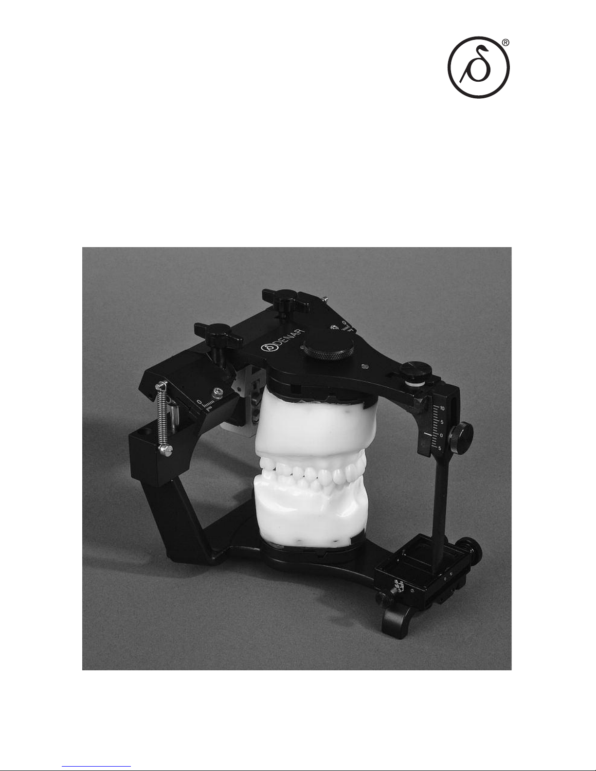
The Dénar®
Mark II System
TECHNIQUE MANUA


The Dénar®
Mark II System
TECHNIQUE MANUA
Published by
Whip Mix Corporation - West
1730 East Prospect Rd., Suite 101
ort Collins, CO 80525
Toll- ree: 1-800-201-7286
ax: 1-970-472-1793
www.whipmix.com

ACKNOW EDGEMENTS
The Mark II System was developed to fill a need that existed primarily in dental
schools, but also among practicing dentists and laboratory technicians. The Schools
of Dentistry expressed a desire for an effective teaching system that was competi-
tively priced. Practicing dentists and technicians expressed a need for a simple Arcon
articulator that was anatomically accurate which could be used for simple restorative
procedures and to mount diagnostic casts when illustrating occluso-condylar rela-
tions to patients for case presentations. There was also a need for an instrument sys-
tem offering an intermediary step to the incorporation of the principles of occlusion
as well as one offering upward potential to more advanced systems.
We set these needs as our objectives and proceeded to accomplish the task with the
help of many professionals who provided us with both direction and assistance for
which we are most grateful.
Doctors Rex Ingraham, Patrick M. Walker, Donald C. Curntte, Albert Solnit, Howard
M. Landesman, Glen D. Richardson, all at the University of Southern California, gave
us extremely valuable inputs with respect to the needs of the undergraduate stu-
dents. We are indebted to them particularly for their constructive criticism, even
though painful at the time.
A special word of appreciation is expressed to Doctors Sumiya Hobo and rank V.
Celenza for their contributions in the early design phases of the instrumentation system.
In planning the preparation of the Mark II Technique Manual, it was our intent that it
encompass more than just mechanical instruction in the use of the Denar®Mark II
System. We wanted to offer more by also providing related instruction in the theory
of occlusion as it directly pertains to the use of the instrument. Special credit must go
to Dr. Niles . Guichet for his contributions and the time he spent working with us,
particularly in view of the demands of his teaching schedule.
We wish to acknowledge the direction and wisdom that we received from Doctors L.
D. Pankey, Loren Miller, Henry Tanner, James Zuccarella, Mel Steinberg, and Mr. Jack
Snyder, of the Pankey Institute, with respect to how the system can be used by prac-
titioners wishing to render quality dentistry through the incorporation of the principles
of occlusion. A great deal of encouragement in this area was also received from Dr.
Peter E. Dawson to whom we are equally grateful.
To insure the System’s compliance with the purest theories of gnathology we are
most indebted to Dr. Peter K. Thomas. He made what seems like “impossible
demands” to arrive at perfection. ortunately, his toughness was matched with a
great deal of patience.
Through the development phases many different opinions were expressed, but there
was at all times one common goal: to provide dentistry with a quality occlusal instru-
mentation system. We believe we accomplished this goal. This feat took the efforts,
contributions, dedication and assistance of many more people not mentioned, and to
all of them as well: we are very grateful.

CONTENTS
I. Introduction
Who Should Use The Mark II System . . . . . . . . . . . . . . . . . . . . . . . . . . . . . 5
Why Should The Mark II System Be Used . . . . . . . . . . . . . . . . . . . . . . . . . 6
II. The Denar®Mark II Articulator (Semi-adjustable)
Articulator Manipulations. . . . . . . . . . . . . . . . . . . . . . . . . . . . . . . . . . . . . . . 7
Articulator Adjustments . . . . . . . . . . . . . . . . . . . . . . . . . . . . . . . . . . . . . . . . 8
Hand Grasps . . . . . . . . . . . . . . . . . . . . . . . . . . . . . . . . . . . . . . . . . . . . 10-11
III. Relating Condylar Movements to Occlusal Anatomy .........12-16
IV. The Immediate and Progressive Side Shift
Adjustments (Bennett Shift) .................................. 17
V. The Denar®Mark II Facebow/Earbow (Model D31AB)
Locating Three Reference Points on Patient’s ace . . . . . . . . . . . . . . . . . 19
Making the acebow/Earbow Registration . . . . . . . . . . . . . . . . . . . . . . . . 21
Transferring the acebow/Earbow to the Articulator. . . . . . . . . . . . . . . . . 24
VI. Mounting the Casts in the Articulator
The Maxillary Cast . . . . . . . . . . . . . . . . . . . . . . . . . . . . . . . . . . . . . . . . . . . 27
The Mandibular Cast . . . . . . . . . . . . . . . . . . . . . . . . . . . . . . . . . . . . . . . . . 28
VII. Setting the Articulator to Checkbite Records
Simulating the Orbiting Condylar Paths . . . . . . . . . . . . . . . . . . . . . . . . . . 30
Simulating the Protrusive Condylar Paths. . . . . . . . . . . . . . . . . . . . . . . . . 31
VIII. Incisal Table Adjustments
CustomIncisalTable.........................................32
AdjustableIncisalTable.......................................32
IX. Treatment Procedures
ixed and Removable Partial Denture Restorations . . . . . . . . . . . . . . . . . 35
CompleteDentures..........................................35
APPENDICES
A. Checkbite Procedure . . . . . . . . . . . . . . . . . . . . . . . . . . . . . . . . . . . . 36
B. Denar®System Protocol for Dentist-Laboratory Relations . . . . . . . 42
C. Calibration Procedure . . . . . . . . . . . . . . . . . . . . . . . . . . . . . . . . . . . 45
D. Occlusal Plane Analyzer . . . . . . . . . . . . . . . . . . . . . . . . . . . . . . . . . 51
E. Selecting Instruments for Occlusal Treatment. . . . . . . . . . . . . . . . . 55
. Accessories . . . . . . . . . . . . . . . . . . . . . . . . . . . . . . . . . . . . . . . . . . . 58
G. Care and Maintenance. . . . . . . . . . . . . . . . . . . . . . . . . . . . . . . . . . . 60
H. Parts List . . . . . . . . . . . . . . . . . . . . . . . . . . . . . . . . . . . . . . . . . . . . . 61
IMPORTANT
Your Denar®Mark II Articulator and acebow/Earbow are precision instruments man-
ufactured to precise tolerances and designed to give you years of troublefree service.
Like all precision instruments they must be handled carefully to avoid damage. A
thorough study of the information contained in this instruction manual will insure you
of the benefits which these instruments offer.
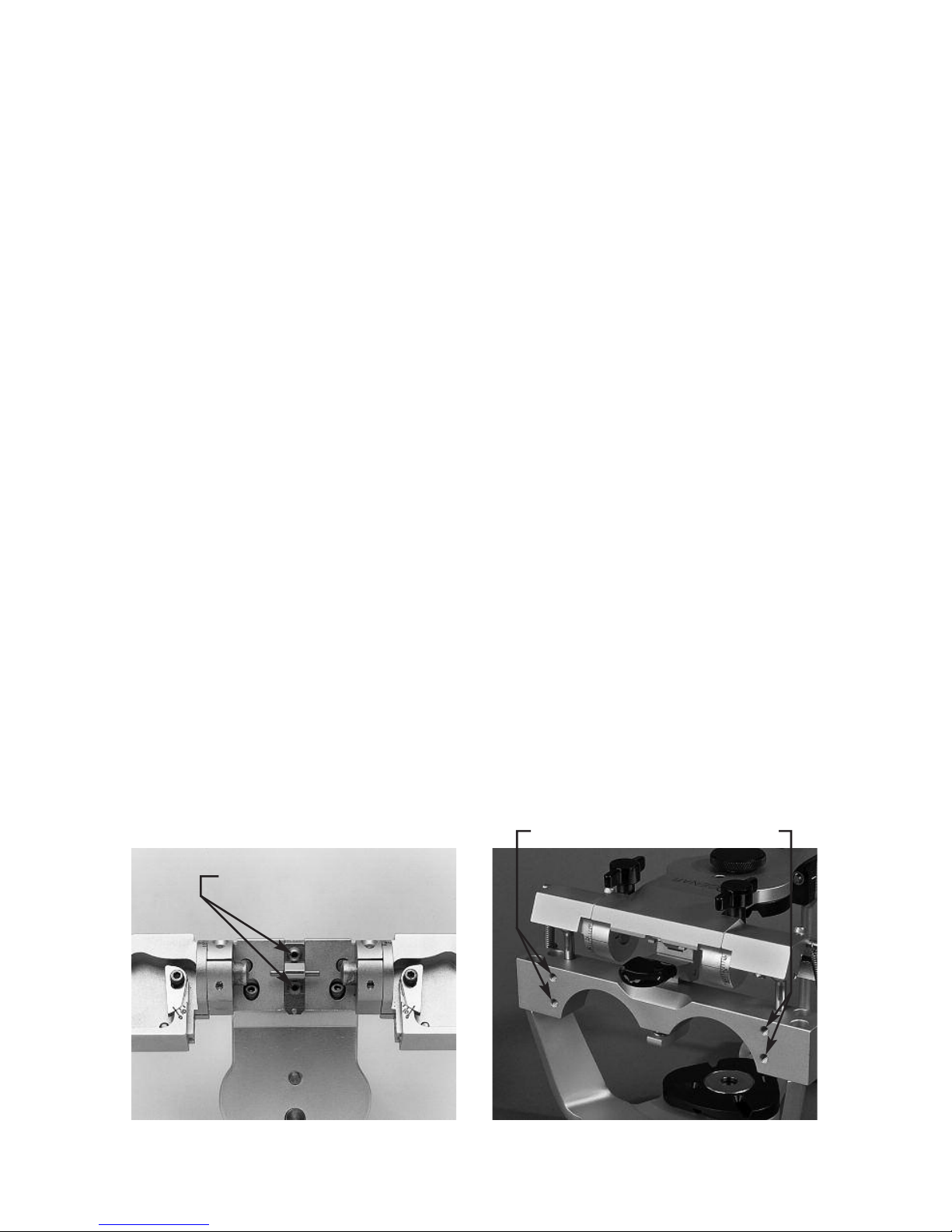
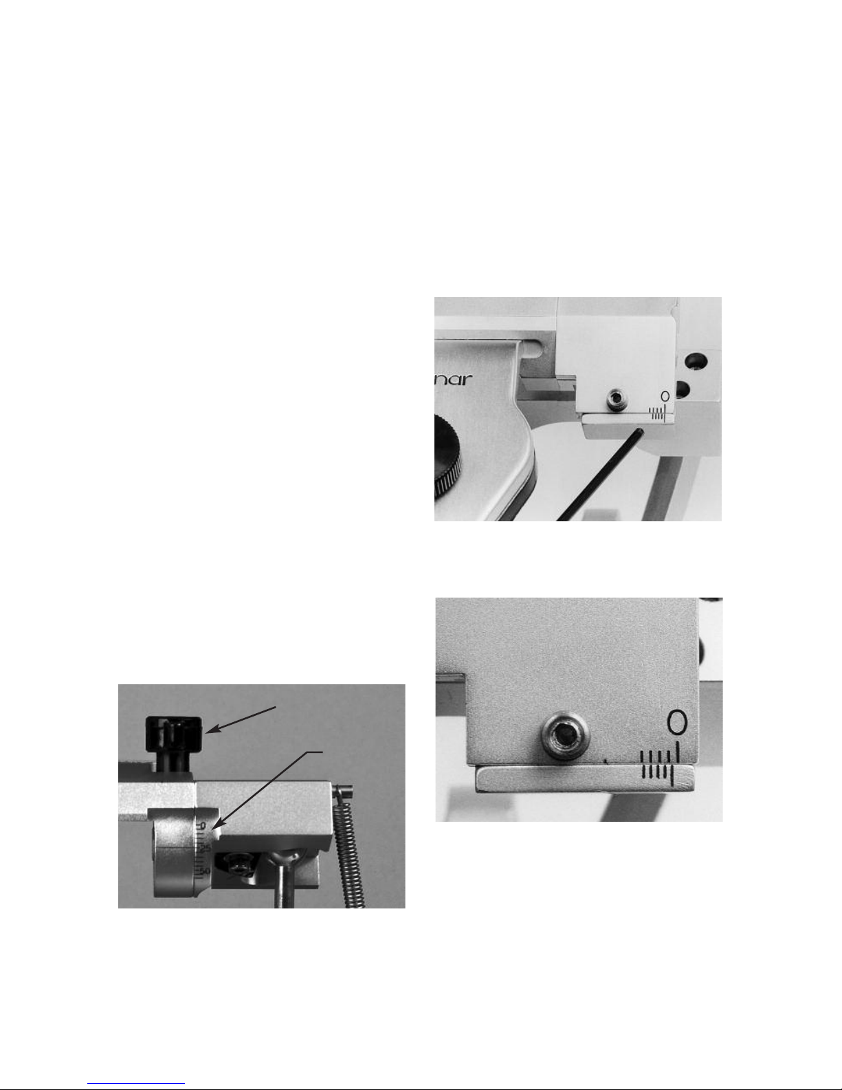
DO NOT ADJUST the factory adjustment screws illustrated in figure 2A. They are for
factory use only. Adjustment of these screws in the field can alter the instrument’s
operation and may require factory repair.
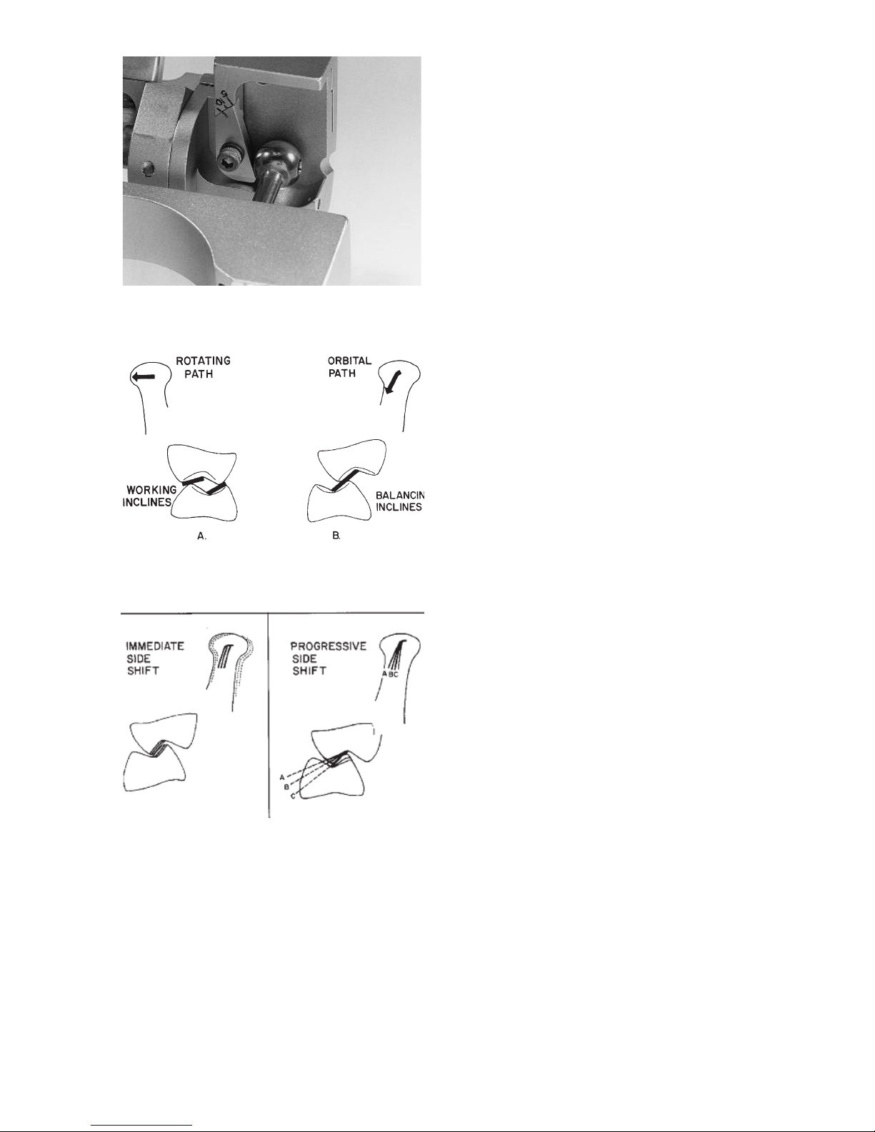
Also the microadjustable adjustment lockscrews illustrated in figure 2B are used to
calibrate the centric relation position of your Mark II articulator to tolerances of plus
or minus one thousandths of an inch from the factory reference position. Adjustment
of these screws can alter the precise factory alignment of your articulator. Do not
modify the setting of these adjustment screws until after you have read this instruc-
tion manual and thoroughly understand the function of these adjustment screws as
explained in Appendix D. These microadjustment screws should only be used in con-
junction with a Denar®ield Inspection Gage to calibrate your articulator.
fig. 2A fig. 2B
Factory Adjustments
Microadjustment Screws

5
I. INTRODUCTION
WHO SHOU D USE THE DÉNAR®MARK II SYSTEM
DOCTORS WHO WANT:
• To mount casts quic ly and easily on a semi-adjustable instrument that
mechanically and accurately reproduces mandibular movements.
• To produce restorations by means of chec bite records and/or the func-
tionally generated path ( GP) techniques.
• A useful tool for diagnosis and for the fabrication of restorations when not
utilizing a pantograph and fully adjustable articulator.
• A semi-adjustable articulator with the immediate side shift adjustment
capability.
• Casts mounted on a very rigid articulator in the position of maximum inter-
cuspation.
• To incorporate the benefits of the Denar®Two Instrument System.
TECHNICIANS WHO WANT:
• A practical, rigid and easy to use articulator.
• To efficiently produce restorations that require fewer remakes than restora-
tions constructed on articulators of lesser adjustment capability.
• To receive mounted casts.
• To service dentists using the Denar®Two-Instrument System.
EDUCATORS WHO WANT:
• An economically priced articulator and facebow for student issue without
violating sound anatomical principles.
• Occlusal instruments that fulfill the needs of all restorative departments.
•To avoid the need for the student having a separate articlulator for each
restoration under construction.
STUDENTS WHO WANT:
• To study Occlusion and the movement of the temporomandibular joint.
A means of progressing to a fully adjustable articulator and pantograph.

6
WHY SHOU D THE
MARK II SYSTEM BE USED
Simple and Practical to Use
The Denar®Mark II Articulator and
acebow System enables the user to
quic ly and easily mount casts of a
patient’s teeth on an instrument that is
both an equivalent of their natural rela-
tionship and which also can be mechan-
ically programmed to simulate the
mandibular movements of the patient.
To accomplish this mechanical equiva-
lence, the Mark II articulator has adjust-
ment capability to duplicate the more
clinically significant movements of the
mandible. Those condylar paths of
movement of lesser clinical significance
have not been ignored, but instead, are
constructed to average anatomic
dimensions.
Accurate Dia nostic and
Treatment System
The Mark II System is a particularly use-
ful tool for the diagnosis and for the fab-
rication of restorations when not utilizing
a pantograph and fully adjustable artic-
ulator. The simplicity and accuracy with
which the system may be used enables
the user to produce precision occlusal
restorations that require significantly
less in the mouth modifications than
restorations constructed on articulators
of lesser adjustment capability.
Excellent Learnin Tool
The Mark II System is built around
sound principles of human anatomy and
is consequently ideal for study of TMJ
characteristics and theories of occlu-
sion. Understanding this system facili-
tates progress to a fully adjustable artic-
ulator as the movements and adjust-
ments are the same.
Constructed with Clinically
Needed Features
The Mark II System is easy to use. The
articulator is rigid with a very positive
centric lock. It is of the Arcon construc-
tion with the back designed for maxi-
mum lingual visibility to the casts. The
upper and lower bows come apart and
lock together in the open and closed
positions (no rubber bands needed).
The articulator can be placed level in the
upside down position for mounting the
casts without the need of a plastering
stand. The facebow sidearms are inde-
pendently adjustable and can be locat-
ed to either the hinge axis or the exter-
nal auditory meatus (opening) of the
ears.
Economical
The Mark II Articulator which is compet-
itively priced is also two instruments in
one. Not only is it a semiadjustable
articulator with the features described
above, but also because of the microm-
eter adjustments in the condylar areas,
the condyles can be adjusted three
dimensionally with the Denar®ield
Inspection Gage to tolerances of plus or
minus .001 inches (.025 mm) which
allows transfer of the mounted casts to
other Denar®articulators. This feature
reduces the need for a separate articu-
lator for every restoration under con-
struction.
7
In order to be proficient in the use of the
articulator to diagnose condylar paths of
movement and to fabricate occlusal
restorations, the operator must have
knowledge of:
• The articulator condylar controls
and how to adjust them.
• The proper hand grasps for manip-
ulating the articulator through its
excursive movements.
In this section of this manual we will first
discuss the simple procedure of how to
open and close the articulator properly
and how to operate the centric latch.
Secondly we will discuss the location of
the articulator condylar controls and
how to adjust them. Lastly we will cover
the proper hand grasps for manipulating
the articulator through its excursive
movements. How to adjust the articula-
tor to checkbite records is discussed in
another section of this manual.
ARTICU ATOR MANIPU ATIONS
To assemble the articulator hold the
upper bow approximately parallel to the
lower bow and simply place it on the
lower bow.
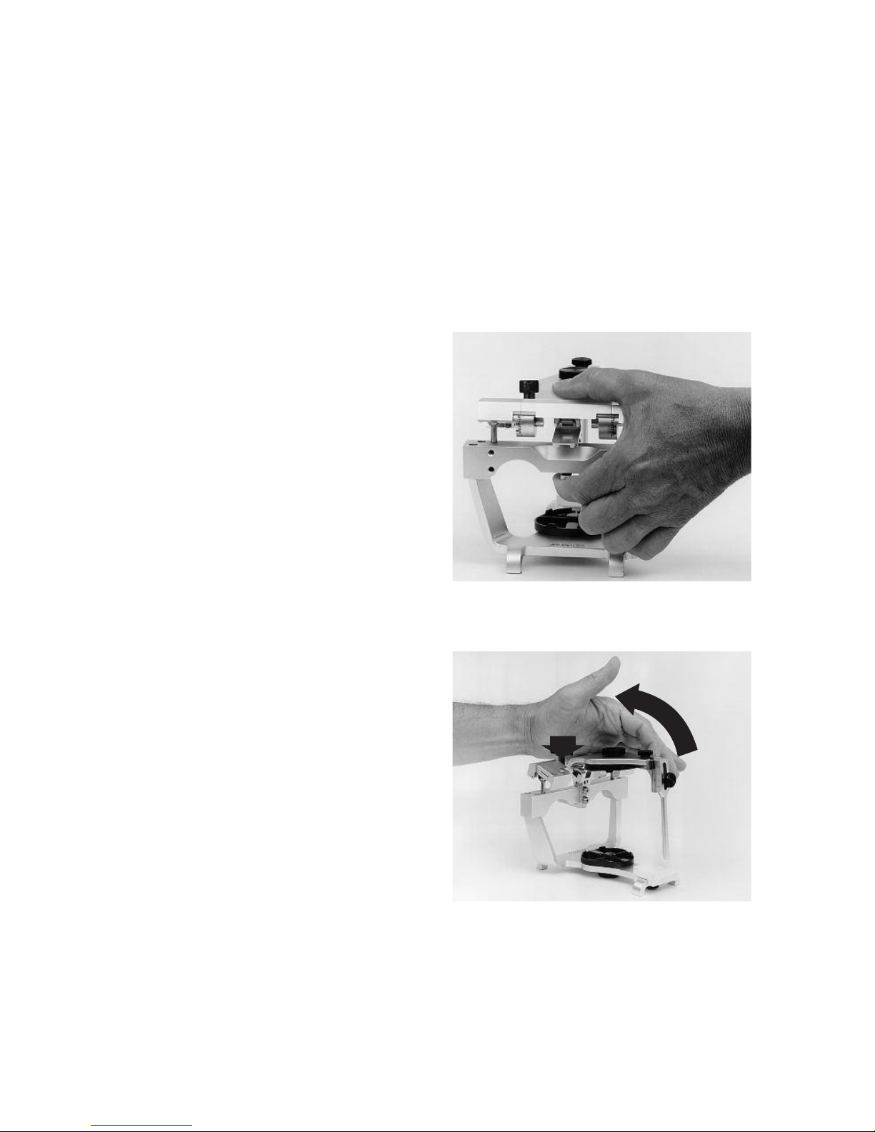
Centric Latch Operation
When the articulator is closed it can be
locked in the centric position by pushing
the centric latch to the down position.
The centric latch is opened by placing
the index finger on the trigger located
underneath the center of the crossbar of
the lower bow and by placing the thumb
on top of the upper bow (fig. 3). Next
apply pressure with the index finger; it
must be released by the trigger. When
the centric latch is open the upper bow
can be removed from the lower bow by
lifting it vertically while maintaining the
upper bow parallel to the lower bow.
To Open the Articulator
Apply downward pressure to the top of
the upper bow over the centric latch and
fossa assemblies with the heel of the
palm of the left hand and simply open
the articulator. The opening movement
of the articulator automatically engages
the centric latch and locks it (fig. 4).
II. THE DÉNAR®MARK II ARTICU ATOR
fig. 3
fig. 4
8
To Lock in the Open Position
When the articulator is opened, the
upper bow can be moved downward
toward the lower bow so that the
condyles move forward in their fossae to
engage the lock open position (fig. 5).
To Close the Articulator
To close the articulator move the upper
bow up and forward to disengage the
lock-open position and close the articu-
lator (fig. 6).
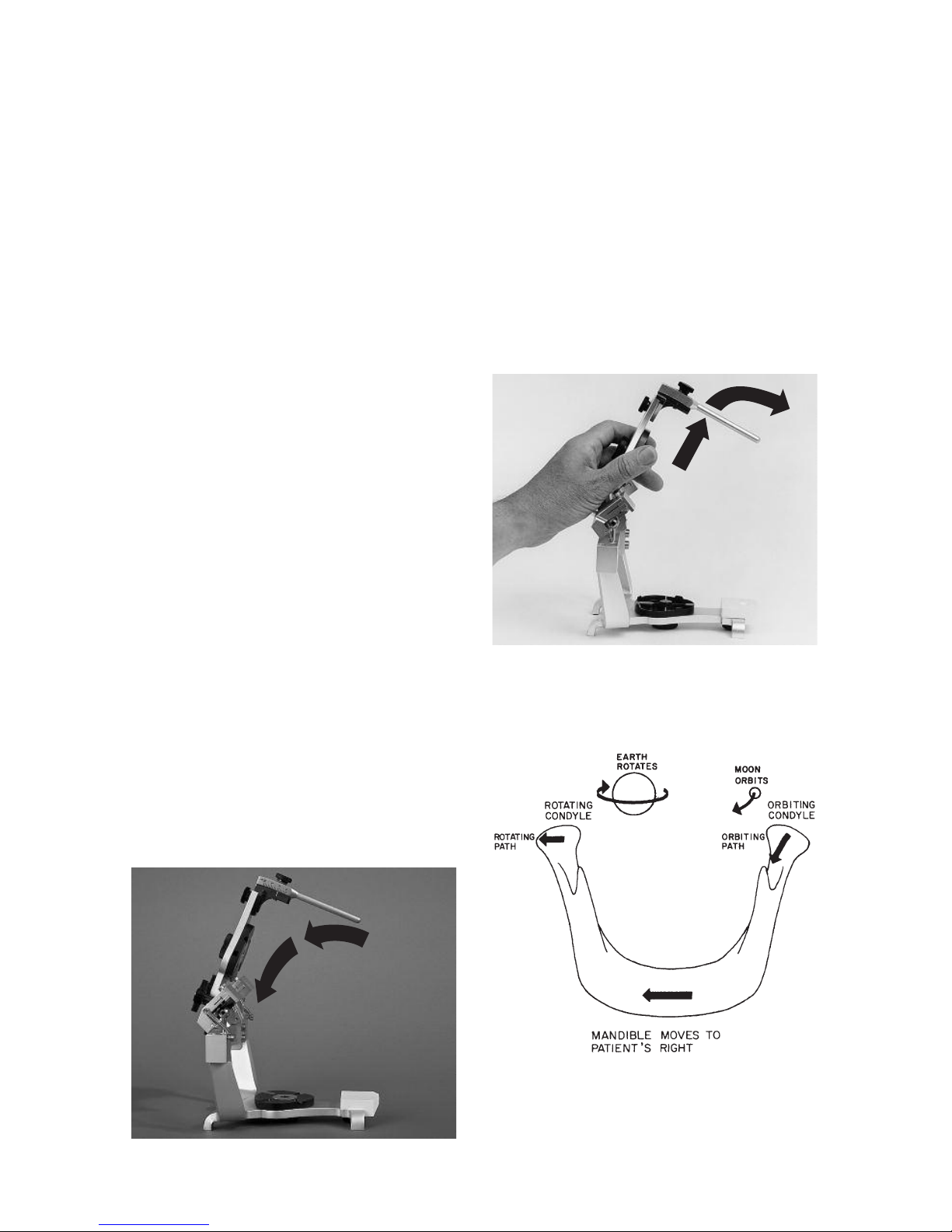
ARTICU ATOR ADJUSTMENTS
The articulator is a mechanical equiva-
lent of the lower half of the head __ a
mechanical jaw so to speak. In order to
discuss the adjustments of the articula-
tor or specifically the fossa controls, it
would be helpful to discuss the condylar
paths of movement of the human
mandible. In a lateral mandibular move-
ment the condyle on the side toward
which the mandible moves is termed the
rotating condyle (fig. 7). The condyle on
the side opposite the side towards
which the mandible moves is termed the
orbiting condyle.
In a lateral mandibular movement the
orbiting condyle moves inward, down-
ward and forward and orbits about the
rotating condyle which is simultaneous-
ly rotating and moving outward during
the mandibular side shift.
orbitin path - the path of move-
ment of the orbiting condyle.
rotatin path - the path of move-
ment of the rotating condyle.
protrusive path - the path of
movement of the condyle in a
straight protrusive movement.
fig. 5
fig. 6
fig. 7
9
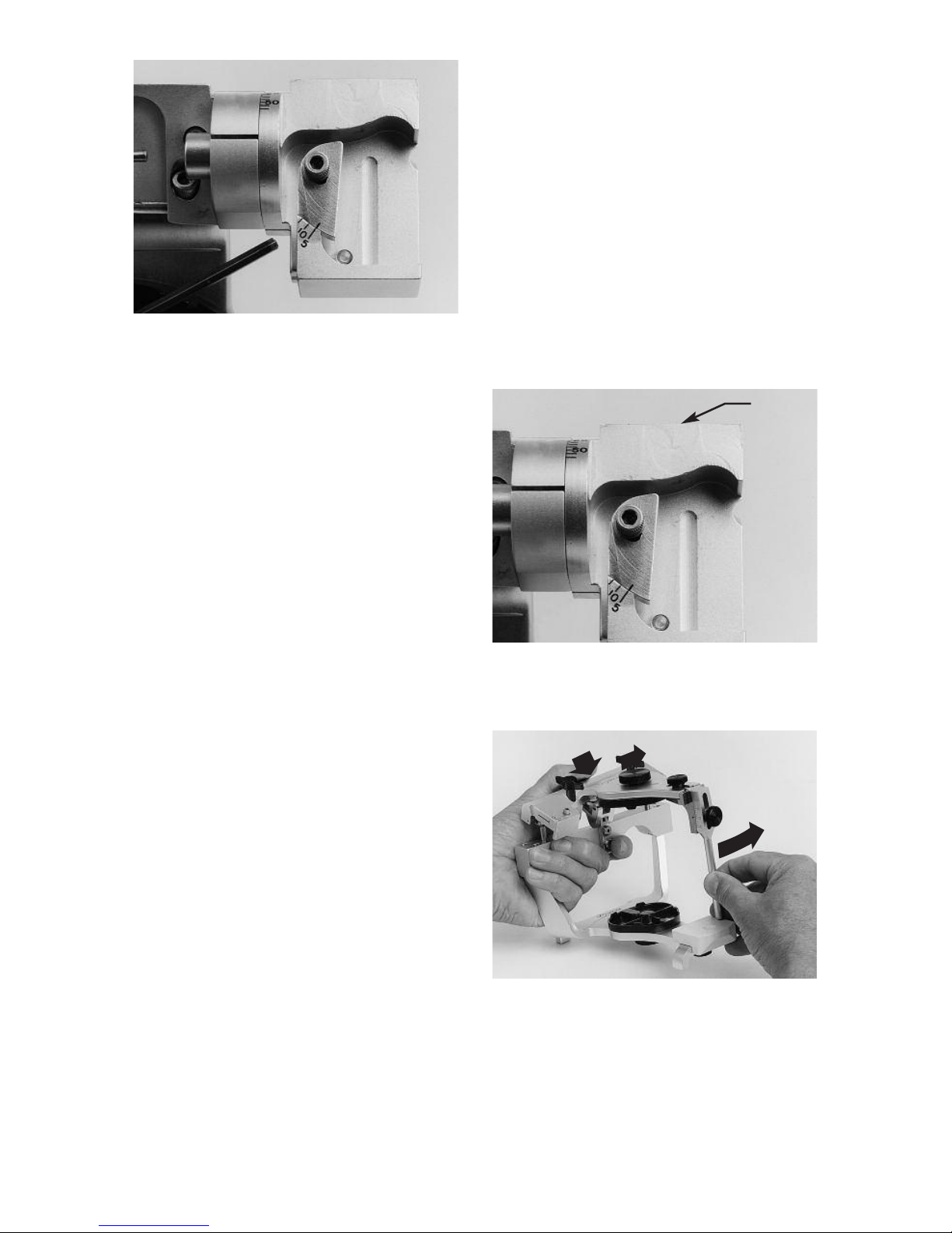
Protrusive Adjustments
The inclination of the protrusive condy-
lar path can be adjusted by loosening
the protrusive adjustment lockscrew.
The protrusive condylar path inclination
scale is below the protrusive adjustment
lockscrew and is calibrated in incre-
ments of 5 degrees (fig. 8).
Immediate Side Shift Adjustment
The medial fossa wall can be displaced
straight medially by means of the imme-
diate side shift adjustment. The scale for
the immediate side shift adjustment is
lateral to the adjustment lock screw on
top of the fossa (fig. 9). The scale is a
Vernier scale calibrated in .2 millimeter
increments. The scale reads medialward
from its lateral extremity.The index in fig.
10 indicates an immediate side shift set-
ting which is more than 0 but less than 1
full millimeter. By reading the Vernier
scale on the lower portion of the scale
medialward from the index it can be
determined that the immediate side shift
is .6 of a millimeter since it is the third
graduation that lines up with a millimeter
graduation on the upper portion of the
scale.
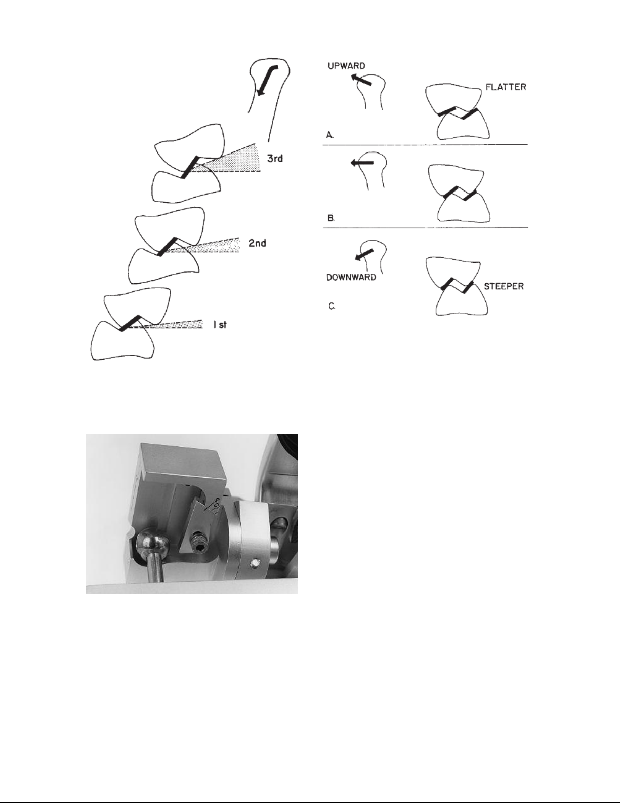
Pro ressive Side Shift Adjustment
The angle of inclination of the medial
fossa wall to the sagittal plane be
adjusted by loosening the progressive
side shift adjustment lockscrew and
moving the insert from 5 to 15 degrees.
The scale for the progressive side shift
adjustment is anterior to the adjustment
lockscrew and is calibrated in 5 degree
increments. (fig. 11).
fig. 8
fig. 9
fig. 10
Scale
ockscrew
10
Rear Wall Inclination
The posterior fossa wall of the Mark II
Articulator is nonadjustable but is con-
structed to average anatomic dimen-
sions. It is inclined posteriorly 25
degrees to allow for a backward move-
ment of the rotating condyle as it moves
outward (fig. 12).
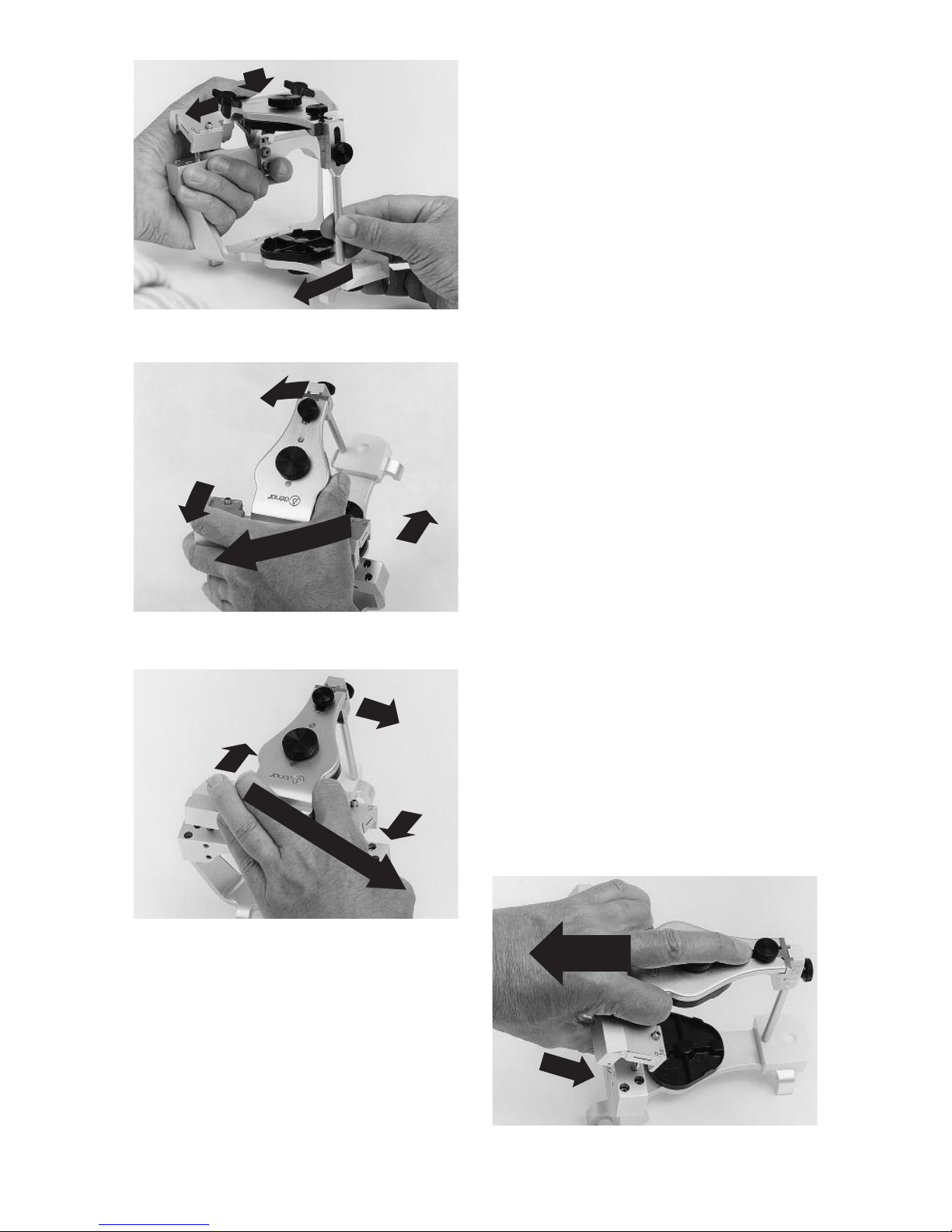
HAND GRASPS
To use the articulator properly the oper-
ator must master the proper hand
grasps. A right handed operator curls
the fingers of the left hand under the
mandibular crossbar and places his left
thumb on top of the upper bow (fig. 13).
To effect both left and right lateral excur-
sive movements the left thumb guides
the back of the upper bow while the
forefinger and thumb of the right hand
holds the incisal pin moving it in the
desired direction. These hand grasps
can be best described as the underhand
push __ pull grasps and the underhand
protrusive grasps. In order to execute
lateral movements the centric latch
must be open.
Underhand Push Grasps
To effect a right lateral mandibular
movement be sure the latch is open and
move the upper bow to the left. (The left
side of the articulator is the left side of
the instrument as it is viewed from the
rear.) Pressure is applied with the left
thumb to insure the left orbiting condyle
maintains contact with its superior and
medial fossa walls and the right rotating
condyle maintains contact with its supe-
rior and rear fossa walls (fig. 13).
fig. 11
fig. 12
fig. 13
Rear
Wall
11
Underhand Pull Grasps
To effect a left lateral mandibular move-
ment the upper bow is moved to the
right and pressure is applied with the
left thumb to insure that the right orbit-
ing condyle maintains contact with its
superior and medial fossa walls and the
left rotating condyle maintains contact
with its superior and rear fossa walls
(fig. 14).
Underhand Protrusive Grasps
(Protrusive Push Grasp)
To effect a straight protrusive movement
the upper bow is moved straight poste-
riorly with the right hand and the left
thumb is used to apply downward pres-
sure on the back of the upper bow so
that the condyles maintain contact with
their superior fossa walls.
The overhand grasps as contrasted
from the underhand grasps are also
useful in manipulating the articulator
and are required to efficiently set a fully
adjustable articulator to a pantographic
record. igure 15 illustrates the
Overhand Push Grasp; fig. 16 the
Overhand Pull Grasp, and fig. 17 the
Overhand Protrusive Grasp. When
employing the overhand grasps to
manipulate the articulator be sure to
apply pressure to the back of the articu-
lator to insure that the condyles main-
tain contact with their respective fossa
bearing surfaces.
fig. 14
fig. 15
fig. 16
fig. 17
12
The Dénar®Mark II Articulator is of the
Arcon construction; i.e., the condyles
are attached to mandibular bow and the
fossa assemblies are fixed to the maxil-
lary bow. This construction which is a
facsimile of the anatomical structures,
enables the articulator to more accu-
rately simulate condylar paths of move-
ment. In addition this construction
makes it easy to understand the relation
of condylar paths of movement to
occlusal anatomy.
An understanding of the relationships
which exist between condylar paths of
movement and occlusal anatomy is an
invaluable aid in the use of an articulator
for diagnosis and treatment. The follow-
ing exercises which utilize the articulator
as a teaching method are helpful to
enable you to quickly understand these
relationships.
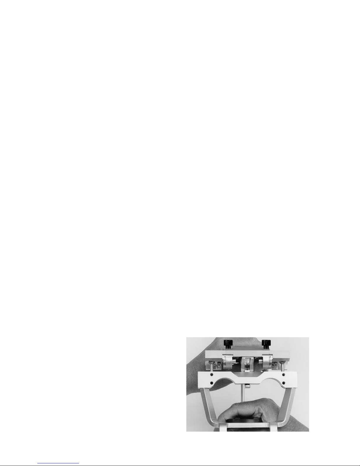
Set the left immediate side shift adjust-
ment to 1 millimeter and left progressive
side shift adjustment to 15 degrees. By
observing the articulator movements
from the back of the articulator it is easy
to understand why the immediate and
progressive side shifts are so named
(fig. 18). Hold the articulator in centric
relation. Since the left medial fossa wall
is set to permit a one millimeter immedi-
ate side shift, centric relation is achieved
when the right condyle touches its
medial fossa wall.
Move the articulator in a right lateral
mandibular movement until the left
orbiting condyle contacts its medial
fossa wall and note that the rotating
condyle and mandible move immediate-
ly to the right. As you continue the right
lateral mandibular movement the orbit-
ing condyle move downward, forward
and inward. Note that during this move-
ment of the orbiting condyle the rotating
condyle and mandible move progres-
sively more to the right as the orbiting
condyle advances. Repeat this articula-
tor movement and note that the rotating
condyle moves immediately to the right
and then progressively more to the right
as the orbiting condyle advances.
mandibular side shift (Bennett Shift):
the bodily side shift of the mandible
which occurs during a lateral jaw
movement.
immediate side shift: a mandibular
side shift in which the orbiting condyle
moves essentially straight medially as
it leaves centric relation.
pro ressive side shift: a mandibular
side shift which occurs at a rate or
amount which is directly proportional
to the forward movement of the orbit-
ing condyle.
By observing a right lateral mandibular
movement from the front of the articula-
tor you can see that the path of move-
ment of the orbiting condyle (orbiting
path) as it moves inward, downward and
forward is guided by the superior, rear
and medial fossa walls (fig 19). This
condylar path of movement is associat-
ed with and has its principal effect on
the balancing inclines of cusps on the
orbiting side (fig. 20B).
III. RE ATING CONDY AR MOVEMENTS
TO OCC USA ANATOMY
fig. 18
13
of the marginal ridge, fossa, or central
groove of the tooth (fig.21).
An increase of the progressive side shift
movement of the articulator has an effect
of flattening the balancing inclines of
cusps on the orbiting side mediolaterally
(fig. 22).
The closer a cuspal incline is to a condylar
path of movement the greater is the influ-
ence that condylar control has on occlusal
anatomy. Consequently due to the fact
that the orbiting condyle is moving down-
ward so rapidly as it moves forward, we
observe that as we move more distally in
the dental arches the lingual cusps of
maxillary molars project increasingly
downward and the buccal cusps of
mandibular molars project increasingly
upward to harmonize the occlusion to
condylar paths of movements (fig 23).
Again by observing a right lateral condylar
movement from the front of the articulator
you can see that the path of movement of
the rotating condyle (rotating path) as it
moves outward is guided by the rear and
top fossa walls (fig.24). This path of move-
ment is most closely associated with and
has its principle effect on the working
inclines of cusps on the working side (fig.
20A).
The rotating condylar path may be inclined
upward or downward as the rotating
condyle moves outward. This upward and
downward inclination of the rotating
condylar path in the coronal plane has its
principle influence on the height of the
working inclines of posterior cusps on the
rotating side (fig. 25). If the rotating condy-
lar path is inclined upward the cusps must
be flatter (fig. 25A). If the rotating condylar
path is inclined downward the cusps may
be steeper (fig. 25C). The Mark II Articu-
lator cannot be adjusted to upward or
downward movements of the rotating
condyle.
fig. 19
fig. 20
fig. 21 fig.22
Three articulator adjustments establish the
character of the orbiting path on the artic-
ulator: the immediate side shift adjustment,
the progressive side shift adjustment and
the protrusive inclination of the superior
fossa wall.
An increase of the immediate side shift
movement of the articulator has an effect
of increasing the bucco-lingual dimension
14
The rotating condylar path may be inclined
forward or backward as the rotating
condyle moves outward. This forward and
backward inclination of the rotating
condylar path in the horizontal plane has
its principle effect on the intermeshing of
the working inclines of cusps on the work-
ing side (ridge and groove direction).
The Dénar®Mark II Semi-adjustable
Articulator has the rotating condylar path
reset to the average anatomic inclination
(out and backward 25 degrees).
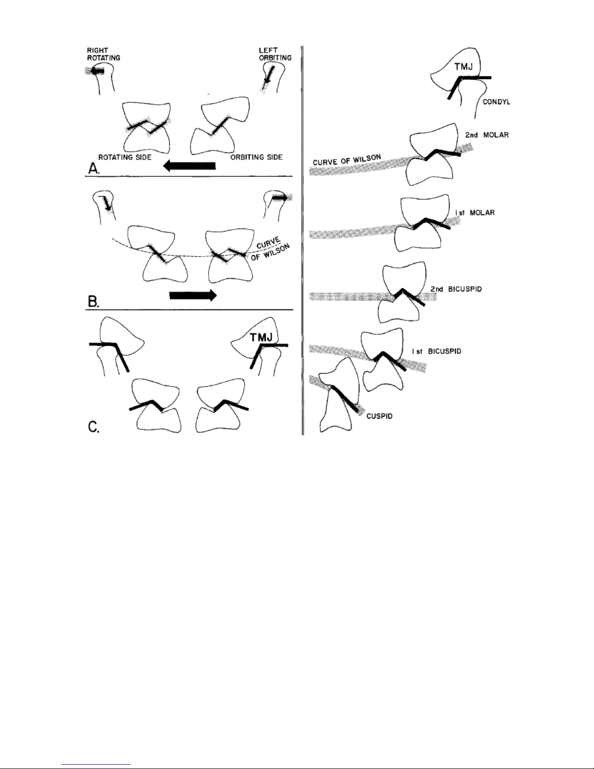
igure 26A illustrates a frontal view of
molar tooth relations in a right lateral
mandibular movement. Although the rotat-
ing condyle moves straight outward the
functioning tooth inclines on the rotating
side have a slight downward inclination
due to the fact that the path of movement
of the orbiting condyle is inclined remark-
able downward.
fig. 24
fig. 25
fig. 23
15
The closer the functioning tooth incline is
to the condylar path of movement the
more the tooth incline simulates that
condylar path of movement.The interrelat-
ing tooth inclines on the orbiting side in
figure 26A have steep inclines to comple-
ment the path of movement of the orbiting
condyle.
igure 26B illustrates a left lateral move-
ment. Due to the fact that the left rotating
condyle is moving straight outward the left
maxillary buccal cusps must be kept short
to allow the left mandibular buccal cusps
to escape. It is this influence of the rotat-
ing and orbiting condylar paths on
occlusal anatomy that establishes the
Curve of Wilson. The more posteriorly we
progress in the dental arches the
mandibular teeth take on a greater lingual
inclination and the maxillary teeth take on
a greater buccal inclination to harmonize
occlusal anatomy to condylar paths of
movement (fig. 27). The condyle tracks a
path in its fossa just as a buccal cusp of a
lower molar tracks a path in its fossa on
the occlusal surface of an upper molar. or
all practical purposes in the use of articu-
lators to establish dental articulation, the
temporo-mandibular joint can just be
thought of as another tooth, the fourth
molar__ another anatomic control of jaw
movement (figs. 26C and 27).
fig. 26 fig. 27
16
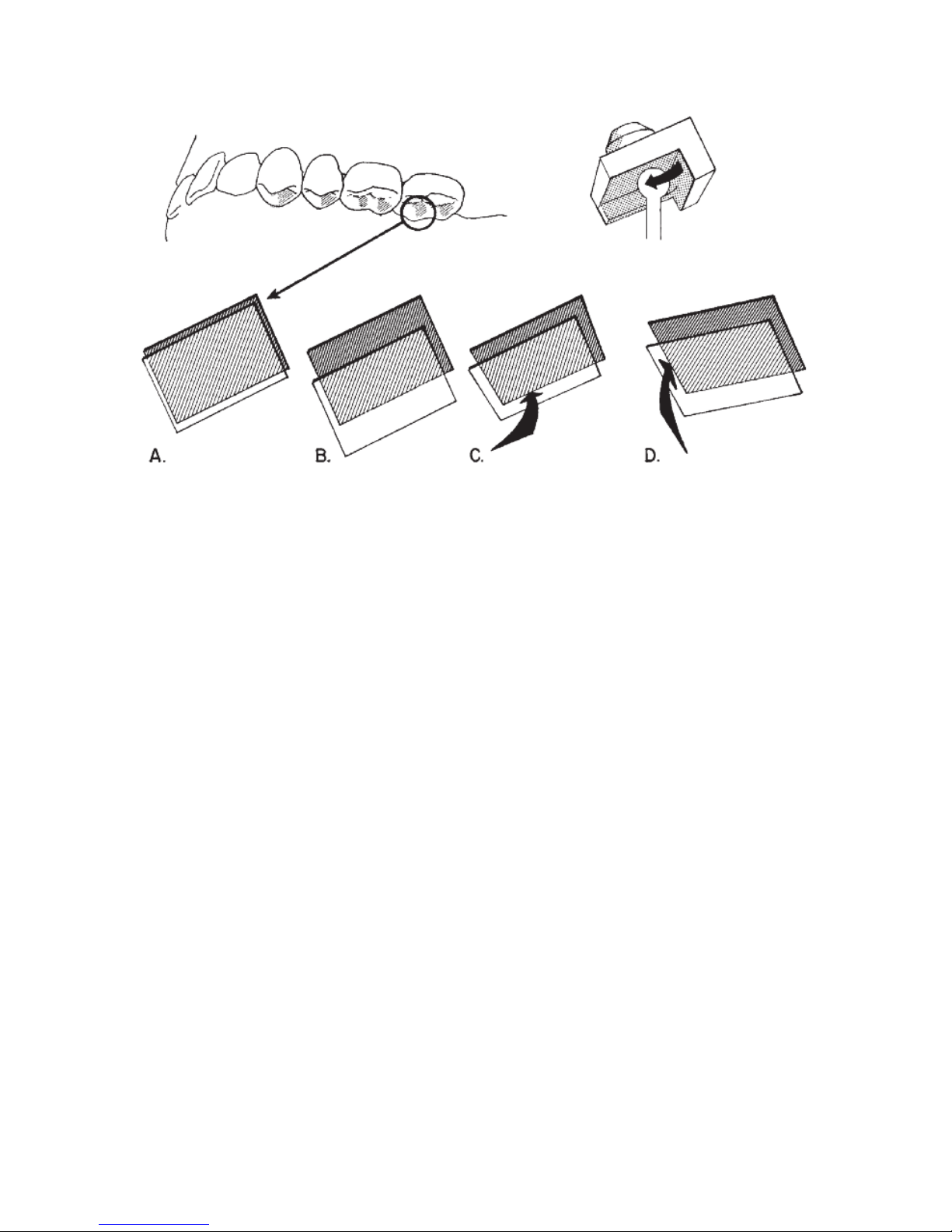
To facilitate a clear understanding of the
relation of the orbiting condylar path to
occlusal anatomy study fig. 28.
Illustrated are the cuspal inclines of the
left bicuspids and molars which are
associated with the orbiting condylar
path. It is the distal aspects of the max-
illary lingual cusps’ buccal inclines
(shaded) which interrelate with the
mandibular buccal cusps’ lingual
inclines, mesial aspects. In your mind’s
eye it is helpful to dissect out these cus-
pal inclines (fig. 28A) and visualize what
influence a change in the character of
the orbiting path on the articulator
would have on these aspects of the
cusps. Three articulator controls estab-
lish the character of the orbiting path on
the articulator __ the immediate side
shift adjustment and the inclination of
the medial and superior fossa walls. In-
creasing the immediate side shift adjust-
ment on the articulator increases the
clearance between these cuspal inclines
(fig. 28B). Increasing the progressive
side shift movement of the articulator
(increasing the inclination of the medial
fossa wall) flattens the cuspal inclines
mediolaterally (fig. 28C). A decrease of
the inclination of the superior fossa wall
flattens the cuspal inclines anterio-pos-
teriorly (fig. 28D).
fig. 28
17
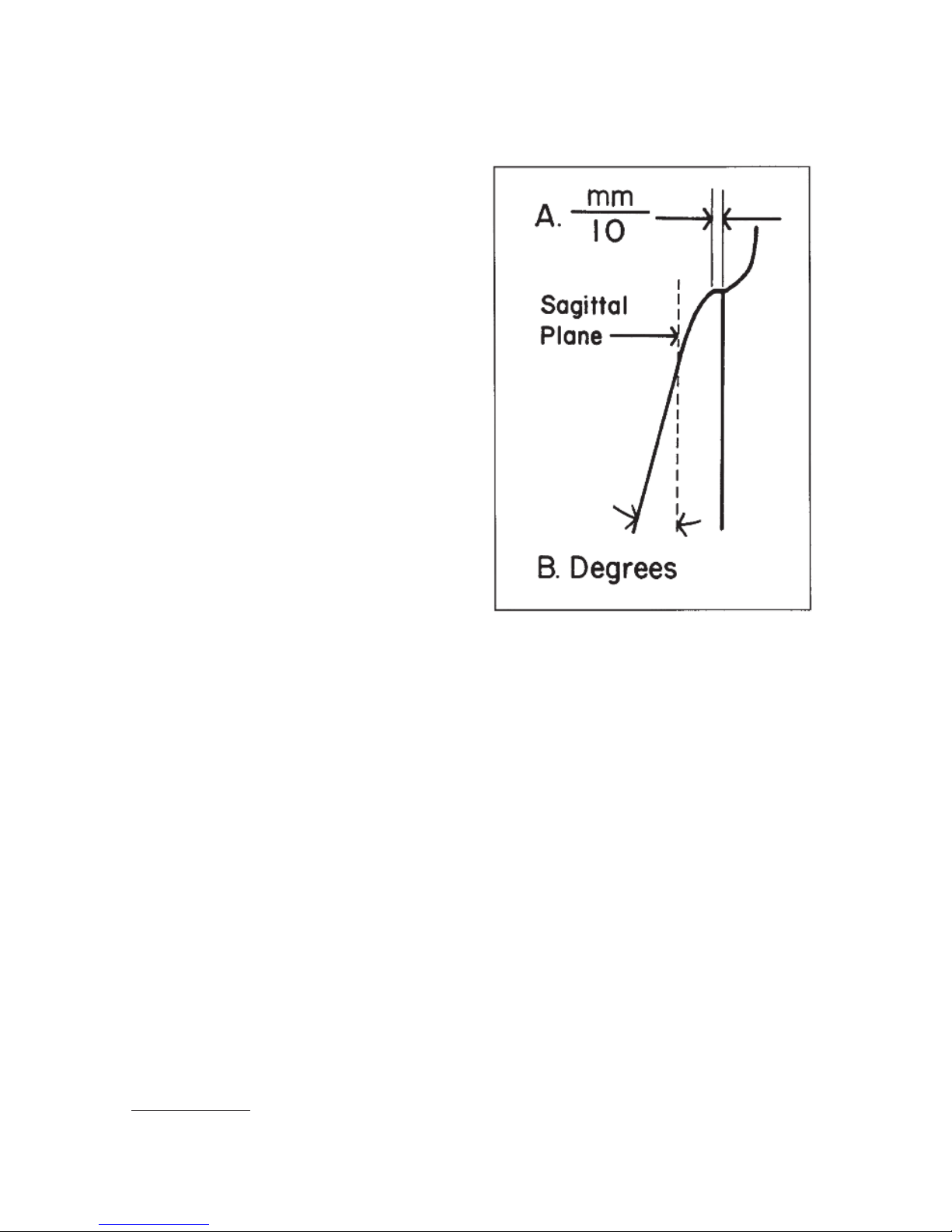
It should be noted that unlike most
semi-adjustable articulators the Denar®
Mark II Semi-adjustable Articulator has
the capability of more accurately simu-
lating the mandibular side shift (Bennett
Shift) by more accurately simulating the
component condylar movements: the
immediate side shift and the progressive
shift. The immediate side shift is
expressed in units of tenths of a millime-
ter (fig. 29A). The progressive side shift
is expressed in degrees (fig. 29B).
The immediate side shift of the mandible
has primary influence on the width of
the central groove of posterior teeth.The
progressive side shift has its principal
influence on the balancing inclines of
posterior cusps on the orbiting side and
on the direction of the ridges and
grooves of posterior teeth, primarily on
the orbiting side.
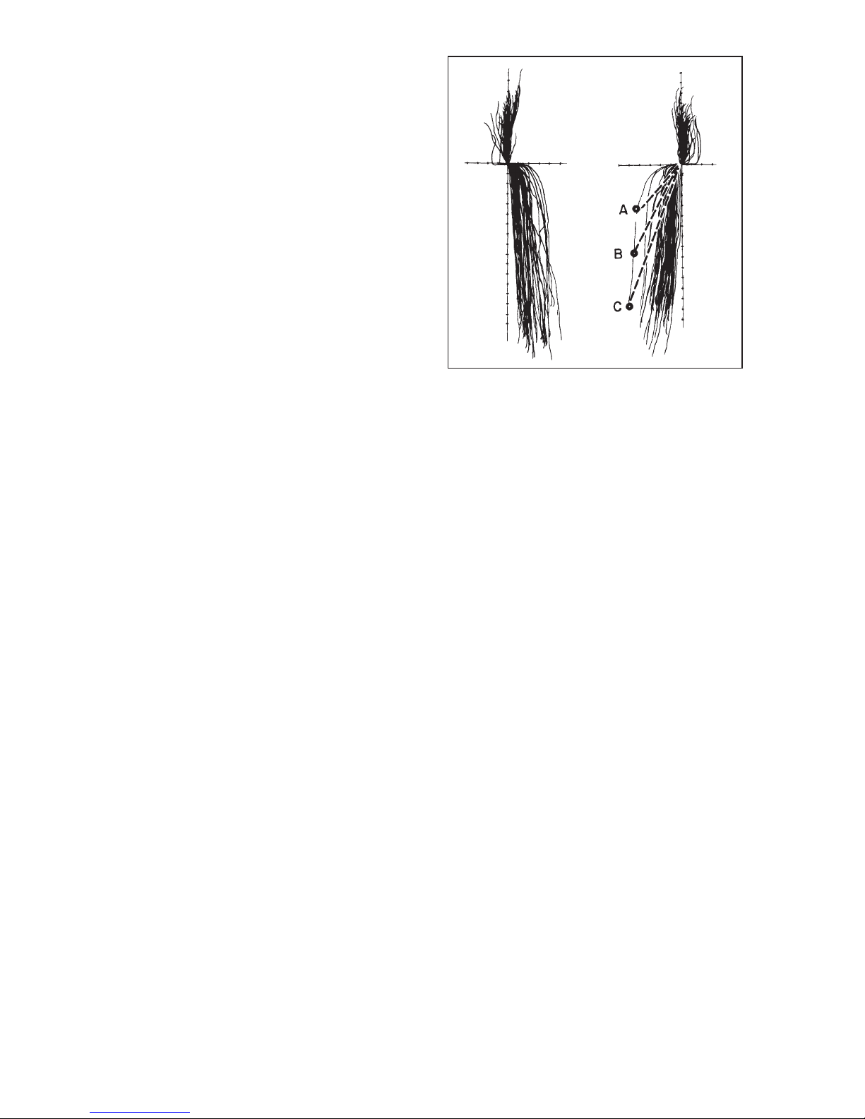
igure 30 illustrates the protrusive, orbit-
ing and rotating path records of the right
and left temporomandibular joints of 50
patients (100 TMJ records). 1 The X and
Y axes are calibrated in increments of 1
millimeter. You will note that the orbiting
path is divided essentially into two com-
ponents: immediate side shift and pro-
gressive side shift. urthermore with few
exceptions once the immediate side
shift has occurred the progressive side
shift records are approximately parallel
to each other and are inclined approxi-
mately five to seven degrees to the
sagittal plane. The biggest variable is
the immediate side shift component of
the orbiting path.
Points A, B and C on one orbiting path
represent three different condylar posi-
tions at which lateral checkbite position-
al records may be taken on one patient.
It should be noted that if an articulator
possessing a progressive side shift and
not an immediate side shift adjustment
were set to each of the three condylar
positions A, B and C as shown in fig. 30.
It would produce three different progres-
sive side shift inclinations correspon-
ding to the three dotted lines in figure 30
__ all of which inclinations would be
wrong. On the other hand, if an articula-
tor possessing a progressive as well as
an immediate side shift adjustment
IV. THE IMMEDIATE AND PROGRESSIVE SIDE
SHIFT ADJUSTMENT (Bennett Shift)
fig. 29
1. Lundeen, Harry C. and Wirth, Carl G.: Condylar Movement Patterns Engraved in Plastic Blocks,
J. Prothet. Dent. December 1973.
Pages 870-875.
18
(Dénar®Mark II) were adjusted so that
the progressive side shift was pre-set to
the average anatomic dimension of six
degrees, one immediate side shift
adjustment setting would intersect with
all three condylar position checkbite
records (A, B, and C) which remar ably
reduce the amount of irritation that oth-
erwise might be introduced in the occlu-
sion. Therefore when adjusting the Mark
II Articulator to lateral checkbite records,
always set the progressive side shift
adjustment to the 6˚ average anatomic
dimension for this diagnostic procedure.
fig. 30
Table of contents
Popular Medical Equipment manuals by other brands


Getinge
Getinge Arjohuntleigh Nimbus 3 Professional Instructions for use

Mettler Electronics
Mettler Electronics Sonicator 730 Maintenance manual

Pressalit Care
Pressalit Care R1100 Mounting instruction

Denas MS
Denas MS DENAS-T operating manual

bort medical
bort medical ActiveColor quick guide

AccuVein
AccuVein AV400 user manual


