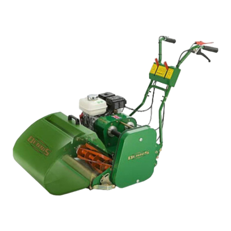
Dennis S500 PLUS User manual

INSTRUCTION MANUAL
DENNIS, Ashbourne Road, Kirk Langley, Derby, DE6 4NJ, United Kingdom
Telephone:- 01332 824777
Fax:- 01332 824 525
E-mail:- [email protected]
www.dennisuk.com SP20002_REV_1
10/12
S500 PLUS

FT Razor Razor Simplex G560 SuperSix G660/G760 Premier Contractor Bray Hand S500 Gang
Application Range 560 Ultra 560 Range G680 Range G860 Range Tools Plus Mower
Bowling Green üüüüüüü
Cricket Ground Maintenance: wicket üüüüüü
square üüüüüü
outeld üüü
Football Pitch üüü
Golf Course Maintenance: Tees üüüüüüü
Greens üüüüüü
Ornamental üüüüü
Croquet Green üüüüüüüü
Grass Tennis Court üüüüüüü
Race Course Maintenance: Parade Ring üüüüüüü
Ornamental üüüüüüüü
Rugby Pitch üüü
Hockey Pitch üü
Sports Club Maintenance üüüüüüüüüüüü
Schools, Colleges & University Grounds üüüüüüüüüüüü
Cemetery Maintenance üüüü
Contractors, Private Lawns & Commercial üüüüüüü
Local Authority & Government Contracts üüüüüüüüüüüü
Ornamental Lawn üüüüüüüü
THIS INFORMATION IS INTENDED FOR GUIDANCE PURPOSES ONLY. WE RECOMMEND THAT YOU DISCUSS YOUR SPECIFIC
REQUIREMENT WITH OUR HEAD OFFICE, SALES MANAGERS OR YOUR LOCAL DENNIS DEALER.
NOTE
Product Application Matrix

3
S500 Plus SP20003_REV_1
Certicate of Conformity
Cylinder mowers powered by Honda GX Petrol Engine
Manufacturer:- Howardson Ltd, Howardson Works, Kirk Langley, Derby, DE6 4NJ. UK
Owner of Technical Document:- Mr I.D. Howard, Howardson Ltd, Howardson Works Kirk Langley, Derby, DE6 4NJ, UK
I the under signed Declare that these machines:-
The reliability and quality of performance of this machine depends upon some simple care maintenance carried out
regularly. This manual has been prepared to allow the user to carry out all such work.
It is advisable to read the instructions carefully. Proper care and attention will enable the machine to give a continuous,
satisfactory, and reliable service. Failure to carry out regular lubrication and maintenance as outlined in this manual may
render any guarantee or warranty invalid.
Inthecaseofanydifculty,oriffurtherinformationoradviceisrequired,ourServiceDepartmentisalwaysatyourcall.In
the interests of speed and accuracy of information please quote the serial numbers of the machine and engine when
making enquiries.
For the machine, this is to be found on a plate attached to the engine deck. The engine number is stamped on either the
crank case or the gear casing facing towards the front of the machine. We suggest you write the numbers on the front
page of this book.
Introduction
Serial Numbers
MACHINE SERIAL NUMBER
MAKE A NOTE OF THE SERIAL NUMBERS OF YOUR MACHINE & ENGINE AND ALWAYS
QUOTE THEM IN ANY COMMUNICATION WITH PERSONNEL AT DENNIS.
NOTE
ENGINE SERIAL NUMBER
Model Operating Width Power (Honda) Measured Sound Power
Level
Guaranteed Sound
Power Level Serial Number
S500 Plus 20” (508mm) GX120 91dB Lwa 94dB Lwa See Product ID range
Tested at:- Howardson Works test site September 2011
Complies with the applicable requirements of:-
- Machine Directive 2006/42/EC
- Noise Directive 2000/14/EC (Annex V)
Managing Director
Ian Howard

4
S500 Plus SP20003_REV_1
Contents
Page
Product Application Matrix.................................................................................................................................................... 2
Declaration of Conformity..................................................................................................................................................... 3
Serial Numbers..................................................................................................................................................................... 3
Introduction........................................................................................................................................................................... 3
Technical Data ...................................................................................................................................................................... 4
Machine Description........................................................................................................................................................ 5 - 6
Important Safety Instructions................................................................................................................................................ 7
Controls ................................................................................................................................................................................ 8
Operating Instructions .......................................................................................................................................................... 9
General Adjustments .......................................................................................................................................................... 10
Routine Maintenance....................................................................................................................................................11 - 12
Storage............................................................................................................................................................................... 12
General Lubrication ............................................................................................................................................................ 12
Notes ..........................................................................................................................................................................13 & 21
Parts Listings............................................................................................................................................................... 14 - 20
Technical Data
Model S500 Plus
A - Width (mm) 840
B - Length with Grassbox (mm) 919
C - Height (mm) 1014
Weight (Kg) 110
Working Width (mm) 560
Engine Honda GX120
Drive System “V” Belt
Final Drive Poly “V” high performance
belts under constant tension
Hand Arm Vibration (m/sec2) 2.5
Measured Sound Power Level dB(A) LWA 91
Guaranteed Sound Power Level dB(A) LWA 94
AB
C

5
S500 Plus SP20003_REV_1
Machine Description
Manufactured with a 20” (51cm) reel width, this machine is powered by a 4 h.p. air cooled, single cylinder, four stroke,
petrol engine. The drive is via a clutching belt.
In the design of the machine, special attention has been given to the importance of easy service and maintenance, with
the construction based on a sectional assembly system. These are: “Reel”, “Handle Bar” and “Drive system”, all of
which can be readily removed from the “Chassis unit”.
1. Stand 8. Seeder Box
2. Reel 9. Latch
3. Belt Guard 10. Seeder Drive Wheel
4. Throttle Lever 11. Exhaust
5. Handle Bar 12. Clutch Lever
6. Air Filter 13. Seeder Control
7. Fuel Tank 14. Stand Latch
1
3
8
4
5
6
7
2
9
14
10
11
12
13

6
S500 Plus SP20003_REV_1
Machine Description
INTERCHANGABLE REELS
There are 2 types of interchangable reels that can be swapped in less than 2 minutes.
Seeder / Slotter Reel
The Seeder / Slotter reel creates germination pockets reducing seed wastage and improving the chances of survival.
Spiker Reel
The Spiker Reel is for surface aeration, punching through the surface pan and allowing water and fertiliser to penetrate to
the root zone.
The 3mm x 20mm slots gives a massive 3% of holes on any green.
Drive Gear
Handle
Seeder /
Slotter Disc
Seeder / Slotter Reel
Drive Gear
Spiker Disc
Handle
Spiker Reel

7
S500 Plus SP20003_REV_1
Important Safety Instructions
In order to operate the machine safely please follow these Health and Safety guidelines.
TRAINING
READ THE INSTRUCTIONS CONTAINED IN THIS MANUAL WITH CARE. IF YOU ARE IN
ANY DOUBT PLEASE ASK YOUR EMPLOYER OR CONTACT US DIRECT AT DENNIS.
CAUTION
• Be familiar with the controls and the proper use of the equipment.
• Never allow children or people unfamiliar with these instructions to use the mower. Local regulations or insurance may
restrict the age of the operator.
• Never mow while people, especially children, or pets are nearby.
• Keep in mind that the operator or user is responsible for accidents or hazards occurring to other people or their
property.
PREPARATION
• While operating always wear substantial footwear and long trousers. Do not operate the mower barefoot or in open
sandals.
•
Thoroughly inspect where the equipment is to be used and remove all stones, sticks, wire, bones and other foreign objects.
PETROL IS HIGHLY FLAMMABLE AND WILL DAMAGE GRASS IF SPILT.
WARNING
A) Storefuelincontainersspecicallydesignedforthispurpose.
B) Refuel out doors and do not refuel whilst smoking.
C) Add fuel before starting the engine. Never remove the cap of the fuel tank or add petrol while the engine is running or
when the engine is hot.
D) If petrol is spilled do not attempt to start the engine but move the machine away from the area of spill and avoid
creating any sources of ignition until the vapours have dissipated.
• Replace damaged or faulty silencers.
• Before using the machine always inspect the safety devices including the cut off switch and the blades for excessive
wear or damage. Replace if necessary.
OPERATION
• DonotoperatetheengineinaconnedspacewheredangerousCARBON MONOXIDE fumes can collect.
• Operateonlyindaylightorgoodarticiallight.
• Always be sure of your footing on slopes.
• Walk. Never run.
• Walk across the face of slopes, never up and down.
• Exercise extreme care on slopes when changing direction.
• Do not operate excessively steep slopes.
• Use extreme caution when reversing or pulling the machine towards you.
• Never operate with defective guards or shields.
• Do not change the engine governor settings or overspeed the engine.
• Start the engine carefully following the instructions with feet well away from the blades.
• Do not tilt the machine when starting the engine.
• Do not put hands or feet near or under rotating parts. Keep clear of the discharge opening at all times.
• Never pick up or carry the machine while the engine is running.

8
S500 Plus SP20003_REV_1
Controls
FOR THE LOCATION OF CONTROLS AND COMPONENTS REF. “MACHINE DESCRIPTION” PAGE 5.
ON / OFF SWITCH (Mounted on the Engine)
This switch stops the engine and can be used to do so at anytime during the operation of the machine. Ensure it is in the
“ON” position before attempting to start the engine.
THROTTLE CONTROL (Item 4)
This controls the RPM of the engine and the resultant speed of the machine. Pushing the lever forwards will increase the
RPM, pulling it back returns the engine to idle.
CLUTCH (Drive Control)
This controls the machines movment. Pulling the lever towards the handle will engage the belt drive and cause the Reel
to rotate, driving the machine forwards
SEEDER CONTROL (Item 13)
For the seeder to operate it must be in the down
position (wheels in contact with ground) see diagram.
To achieve this, release the latches on both sides
(item1).Theseederboxisnowfreetooat,
following the contours on the ground.
The quantity of seed delivered can be varied using
the control on the seeder box handle. By sliding the
control to the right and twisting it forwards /
backwards it can be locked in any of 9 positions to
give the required amount of seed.
When seeding is complete, simply push down on the
handle bars causing the machine to lean backwards and latching onto the seed box. Return the machine to the upright
position and the seed box will raise off the ground.
Item 1

9
S500 Plus SP20003_REV_1
Controls
Operating Instructions
FOR THE LOCATION OF CONTROLS AND COMPONENTS REF. “MACHINE DESCRIPTION” PAGE 5.
PREPARATION FOR USE
• Ensuretheturfisfreefromstonesorotherobstructionswhichmaydamagethereel.
• Checkthemachine(inc.engine)isserviceable,hasallguardsinplaceandhasnovisibledamage.
• Checktheengineoillevel.(FulldetailsaregivenintheENGINEManualsupplied)
• Fillthefueltank3/4fullwithunleadedpetrol.
• Ensurethedriveisdisengaged.
BEFORE YOU OPERATE THIS MACHINE YOU MUST READ AND STUDY THIS MANUAL.
IF YOU ARE IN ANY DOUBT PLEASE ASK YOUR EMPLOYER OR CONTACT US DIRECT.
CAUTION
IMPORTANT INFORMATION PLEASE READ ALL THE DETAILS IN THIS SECTION AND
FAMILIARIZE YOURSELF AND ALL MACHINE OPERATORS WITH THE CONTENTS.
CAUTION
STARTING THE ENGINE
• Switchonthefueltap.
• Switchthecutoffswitchto“ON” (Mounted on Engine)
• Setthethrottlecontroltoahalfopen.
• Shiftthechokelevertothe“Closed” position. (Note: The choke is not required if the engine is warm or the air
temperature high.)
• Grasptherecoilstarthandleuntilresistanceisfelt,thenpullitwithforce.
• Donotallowthestartergriptosnapbackagainsttheengine.Returnitgentlytopreventdamagetothestarter.
• Oncetheengineisstarted,gradually“Open” the choke lever. (Warm-up running of 3-5 minutes is recommended.)
• Setthethrottlecontrolbacktotheidleposition.
STOPPING THE ENGINE
• Setthethrottlecontroltotheidleposition.
• SwitchthecutofftoOFF (Mounted on Engine)
• Closethefueltap.

10
S500 Plus SP20003_REV_1
General Adjustments
HANDLE BAR ADJUSTMENT
The “Handle bars” are adjustable to achieve the
correct working height for the operator.
To set:
• Slacken2-offnuts(Item1)¼”turn
[17mm spanner]
• Raise/lowerthe“HandleBar”tothedesired
position”
• Whenset,tightenthenuts(Item1).
CHANGE A REEL
TheReelcanberemovedeasilyformaintenanceortotaninterchangeableunit.
• Withthestandinthe“Down”position(seeimage1),slackenthe3-offbolts
(item 1) [13mm spanner]
• RotatetheReelhandletoalignthelargeholeswiththeboltheads.
• Pullthehandle,thiswillcausethedrivetodisengageandthereeltoreston
theoor.
• Movetothebackofthemachine,pushdownonthehandlescausingthefront
of the machine to lift.
• Putthestandinthe“Up”position(seeimage2)andsimplymaneuverthemachine
off the Reel. Leaving it on the ground.
• TotthenewReel,reversetheabove.
A
Item 1
Item 1
Image 1
Item 1
Image 2

11
S500 Plus SP20003_REV_1
Routine Maintenance
DRIVING BELTS
ThenaldrivetoreelisviahardwearingTBApoly-Vtypebeltswhichprovidefor
smooth trouble free operation. To ensure the best performance the
following instructions should be carefully followed.
Belt tension is the single most important factor necessary for long, satisfactory service
life of any belt drive.
Under-tensioning leads to belt slip causing rapid wear; over tensioning means
excessive strain on belt and bearings. Between these two extreme conditions is a
reasonable range of tension within which the belt will operate. Belt tension can be
assessedbythe‘deection’method.
CORRECTION CAN BE MADE BY ADJUSTMENT OF THE BELT TENSIONERS. REMOVE
THE DRIVING BELT COVER. THE BELT TENSIONERS ARE RETAINED IN A SLOTTED
HOLE ALLOWING ADJUSTMENT TO BE MADE ONCE THE HOLDING HEXAGON
HEADED BOLTS HAVE BEEN LOOSENED. WHEN ADJUSTED CORRECTLY THE
TENSIONERS SHOULD STILL ROTATE EASILY WITH FINGER PRESSURE. ENSURE THE
TENSIONER BOLTS ARE SECURE BEFORE REPLACING THE COVER.
NOTE
“Beltswillbesufcientlytensionedifthedeectionforceappliedatmidspantoproduceadeectionequalto16mmper
meter of span distance falls between 5 and 9 Newtons per Rib” (TBA Belting).
Inpracticaltermsthisrelatestoabout5mmofdeectionundermoderatengerpressureonthenontensionerside.
Ifttingnewbeltsitisadvisabletoobservethedrivefortherst20-30minutes.Itmaybenecessarytomakean
adjustment to compensate for the normal drop in tension during the run-in period.
OIL / FUEL TYPE & QUANTITY - SPARK PLUG TYPE
Engine Model Oil Type Quantity
(Ltr) Fuel Type Capacity
(Ltr) Spark Plug Type Electrode Gap
(mm)
Honda GX120 Petrol SAE 10W-40 0.6 Unleaded 2.5 BM6ES or BPR6ES 0.7 - 0.8
Area Maintenance First 4 Hours First Month / 20 Hours 3 Months / 50 Hours 6 Months / 100 Hours
Engine Oil Check Level ü
Engine Oil Change ü ü
Air Filter Check Condition /
Clean ü ü
Spark Plug Change ü
ENGINE
ThemachineisttedwithaHondaGX120petrolengine.
Forfullspecicationspleaserefertothemanufacturersinstructionmanualincluded.

12
S500 Plus SP20003_REV_1
Routine Maintenance
CLUTCH CABLE ADJUSTMENT
Over time the cables that operate the drive will need adjusting. This
adjustment can be done at the “Handle Bar” or at the “Chassis”.
To set at “Handle Bar”
• Removerubbercoverfromlever.
• Slackenlocknutsoncable[10mmand7/16”spanner]
• Adjustcabletodesiredtension.
• Whenset,tightenthelocknuts.
To set at “Chassis”
• Slacken2-offlocknutsonrelevantcable[2-off13mmspanners]
• Adjustcabletodesiredtension.
• Whenset,tightenthelocknuts.
ENSURE THE LOCK NUTS ARE TIGHT AND SECURE AND CHECK OPERATION IS
SATISFACTORY BEFORE REPLACING THE CLUTCH COVER AND SCREWS.
NOTE
Storage
The machine should always be kept in a clean dry place, free from condensation. After use ensure that the machine is
thoroughly clean, dry and free from grass and mud.
Under no circumstances must the machine be steam cleaned as this may remove grease from the pre packed bearings.
Because of the nature of lead free petrol we recomend that if the machine is being left unused for more than 2 weeks the
carburetor is run dry. Allow the engine to run out of fuel with the fuel tap switched off.
General Lubrication
REEL
(1-Month)
A grease point is located under the belt guard on the side plate of the machine. This is
to lubricate the internal spur gear that provides drive to the reel. Apply one pump
of grease. Do not over grease.

13
S500 Plus SP20003_REV_1

14
S500 Plus SP20003_REV_1
Item No. Part No. Description Quantity
1 229000 Support Plate 1
2 229004 Engine Bearers 2
3 229005 Cable Stop 1
4 229089 Tie Bar 20” - 22” 1
5 229115 Chain Case Stud 2
6 229492 Retaining Plate Assembly 1
7 229811 Engine Bed 20” (Simplex) 1
8 230004 Support Bracket 1
9 250001 Side Plate L.H. (Slotter) 1
10 250002 Side Plate R.H. (Slotter) 1
11 250021 Collar Front Tie Bar 2
12 250023 Weight Bar 1
13 250024 Stand Leg L.H. (Slotter) 1
14 250025 Stand Leg R.H. (Slotter) 1
15 250026 Stand Leg Brace (Slotter) 1
16 250066 Stand Latch 1
17 250089 Seeder Latch 2
18 J20023 Unit Limiting Stud 2
19 J20064 Grease Nipple 1/4” UNF 1
20 J20297 Serial Number Plate 1
21 SP01009 Hex Set Screw M8 x 20 6
22 SP01021 Hex Set Screw M12 x 20 2
23 SP01025 Cap Head Screw M8 x 30 4
24 SP01027 Hex Set Screw M8 x 40 2
25 SP01035 Hex Set Screw M10 x 25 12
26 SP01043 Cap Head Screw M5 X 16 2
27 SP02002 Nut M5 Nyloc 2
28 SP02006 Nut M8 Nyloc 12
29 SP02008 Nut M10 Nyloc 3
30 SP03004 Washer M8 Toothed 2
31 SP03008 Washer M8 Form A 10
32 SP03016 Washer M10 Form C 3
33 SP05001 Rivet 4.8 x 10 2
34 SP01045 Hex Set M8 x 25 2
1.01 Chassis
29
28
429
25
16
28
6
8
7
30
21
28
31
26 31
2
23
24
33
20
34
31
25
25
22 11 18
31
27
13 19 5
25
9
21
303
32
1
17
21
31
15
12
10
14

15
S500 Plus SP20003_REV_1
2.01 Handle
Item No. Part No. Description Quantity
1 228093 Bolt Saddle M8 x 43 4
2 230013 Console Cover (No Switch) 1
3 230040 Handle Upper W.A. 1
4 250010 Lower Handle Assembly (Slotter) 1
5 250016 Handle Boss (Slotter) 2
6 B32902 Decal Dennis 1
7 J20107 Handle Grip Rubber 2
8 J20108 Throttlle Control Lever 1
9 J20109 Brake Band Lever 1
10 SP01031 Hex Set Screw M10 x 50 2
11 SP01044 Coach Bolt M10 x 25 2
12 SP02005 Nut M8 STD 4
13 SP02008 Nut M10 Nyloc 4
14 SP03004 Washer M8 Toothed 4
15 SP03008 Washer M8 Form A 4
16 SP03009 Washer M5 Form A 4
17 SP03011 Washer M10 Form A 6
18 SP04001 Screw M5 x 16 Slotted 4
NOT SHOWN
- J20112 Throttle Cable 1
- 229723 Drive Cable 1
7
1
14
6
2
9
18
3
8
16
11
4
12
15
10
5
17
13
17
17
13

16
S500 Plus SP20003_REV_1
3.01 Engine & Drive Assembly 1
Item No. Part No. Description Quantity
1 062662 Bearing 6205-2rs 3 1
2 073445 Key 3/16” x 3/16” x 1 1/2” Rd End 1
3 228001 Tapered Bush 1610 - 3/4” 1
4 228002 Tapered Bush 1108 - 3/4” 1
5 228004 Pulley SPZ-71 1
6 228005 Pulley SPZ-132 1
7 228011 Coupling Half (3/4”) 2
9 228103 Coupling Element 1
10 229000 Support Plate 1
11 229003 Drive Pulley Land Roll 1
12 229004 Engine Bearers 2
13 229005 Cable Stop 1
14 229006 Belt Guide Roller Clutch Top 1
15 229007 Belt Guide Roller Clutch Pulley 1
16 229009 Drive Idler Arm 1
17 229011 Pinion Shaft 11T 1
18 229013 Pulley Spacer 1
19 229014 Belt Guide Peg 1
20 229031 Dirt Excluder 1
21 229033 Roller Bearing Housing Oblong 1
22 229038 Tensioner Pulley 1
23 229044 Idler Lever 1
24 229089 Tie Bar 20” - 22” 1
25 229090 Layshaft Guard 20” - 22” 1
26 229091 Bearing Housing 3
27 229092 Bearing Spacer 3
28 229115 Chain Case Stud 2
29 229322 4 Groove Drive Pulley 1
30 229382 Brg Housing 1
31 229492 Retaining Plate Assy 1
32 229811 Engine Bed 20” (Simplex) 1
33 229900 Engine 4.5 Hp Honda GX120 Q9 Type 1
34 230004 Support Bracket 1
35 240088 Slot Blank 1
36 250001 Side Plate L.H. Slotter 1
37 250002 Side Plate R.H. Assy (Slotter) 1
38 250021 Collar Front Tie Bar 2
39 250023 Weight Bar 1
30
63
72
69 18
67
74
23
30
71
75
55
11
59
35 53
20
21
72
64
22
14
66
54
56
26
64
29
72
53
35
18
20
21
11
78
17
63
51 27
56
73
72
15
15
59
671
17
1
62
73
16
3
Item No. Part No. Description Quantity
40 250024 Stand Leg L.H. (Slotter) 1
41 250025 Stand Leg R.H. (Slotter) 1
42 250026 Stand Leg Brace (Slotter) 1
43 250035 Drive Shaft Engine (Slotter) 1
44 250036 Drive Shaft Drive (Slotter) 1
45 250066 Stand Latch 1
46 250089 Seeder Latch 2
47 J20023 Unit Limiting Stud 2
48 J20052 Bearing 6204-2RS 3 5
49 J20064 Grease Nipple 1/4” UNF 1
50 J20297 Serial Number Plate 1
51 J20467 Grub Screw M8 x 8 3
52 J209030 Key 3/16” x 3/16” x 3/4” Rd End 3
53 J209047 Tensioner Pulley 1
54 J209249 Washer 9 x 35 x 3 1
55 SP01008 Hex Set Screw M6 x 16 4
56 SP01009 Hex Set Screw M8 x 20 16
57 SP01021 Hex Set Screw M12 x 20 2
58 SP01025 Cap Head M8 x 30 4
59 SP01027 Hex Set Screw M8 x 40 6
60 SP01035 Hex Set Screw M10 x 25 14
61 SP01043 Cap Head M5 x 16 2
62 SP01045 Hex Set Screw M8 x 25 5
63 SP01068 Hex Set Screw 3/8” UNF x 2 1/2” 1
64 SP01071 Hex Set Screw 3/8” UNF x 1 1/2” 1
65 SP02002 Nut M5 Nyloc 2
66 SP02004 Nut M6 Nyloc 4
67 SP02006 Nut M8 Nyloc 13
68 SP02008 Nut M10 Nyloc 3
69 SP02018 Nut 3/8” UNF Nyloc 1
70 SP02033 Nut 3/8” UNF Lock (Thin) 1
71 SP02034 Nut 3/4” UNF Std 1
72 SP03002 Washer 3/8” 3
73 SP03004 Washer M8 Toothed 16
74 SP03008 Washer M8 Form A 7
75 SP03010 Washer M6 Form A 6
76 SP03016 Washer M10 Form C 7
77 SP05001 Rivet 4.8 x 10 2
78 SP05008 Pin Spirol M5 x 50 1

17
S500 Plus SP20003_REV_1
3.01 Engine & Drive Assembly 1
3.02 Engine & Drive Assembly 2
Item No. Part No. Description Quantity
1 062662 Bearing 6205-2RS 3 1
2 073445 Key 3/16” x 3/16” x 1 1/2” Rd End 1
3 228001 Tapered Bush 1610 - 3/4” 1
4 228002 Tapered Bush 1108 - 3/4” 1
5 228004 Pulley SPZ-71 1
6 228005 Pulley SPZ-132 1
7 228011 Coupling Half (3/4”) 2
9 228103 Coupling Element 1
10 229000 Support Plate 1
11 229003 Drive Pulley Land Roll 1
12 229004 Engine Bearers 2
13 229005 Cable Stop 1
14 229006 Belt Guide Roller Clutch Top 1
15 229007 Belt Guide Roller Clutch Pulley 1
16 229009 Drive Idler Arm 1
17 229011 Pinion Shaft 11T 1
18 229013 Pulley Spacer 1
19 229014 Belt Guide Peg 1
20 229031 Dirt Excluder 1
21 229033 Roller Bearing Housing Oblong 1
22 229038 Tensioner Pulley 1
23 229044 Idler Lever 1
24 229089 Tie Bar 20” - 22” 1
25 229090 Layshaft Guard 20” - 22” 1
26 229091 Bearing Housing 3
27 229092 Bearing Spacer 3
28 229115 Chain Case Stud 2
29 229322 4 Groove Drive Pulley 1
30 229382 Brg Housing 1
31 229492 Retaining Plate Assy 1
32 229811 Engine Bed 20” (Simplex) 1
33 229900 Engine 4.5 Hp Honda GX120 Q9 Type 1
34 230004 Support Bracket 1
35 240088 Slot Blank 1
36 250001 Side Plate L.H. Slotter 1
37 250002 Side Plate R.H. Assy (Slotter) 1
38 250021 Collar Front Tie Bar 2
39 250023 Weight Bar 1
Item No. Part No. Description Quantity
40 250024 Stand Leg L.H. (Slotter) 1
41 250025 Stand Leg R.H. (Slotter) 1
42 250026 Stand Leg Brace (Slotter) 1
43 250035 Drive Shaft Engine (Slotter) 1
44 250036 Drive Shaft Drive (Slotter) 1
45 250066 Stand Latch 1
46 250089 Seeder Latch 2
47 J20023 Unit Limiting Stud 2
48 J20052 Bearing 6204-2RS 3 5
49 J20064 Grease Nipple 1/4” UNF 1
50 J20297 Serial Number Plate 1
51 J20467 Grub Screw M8 x 8 3
52 J209030 Key 3/16” x 3/16” x 3/4” Rd End 3
53 J209047 Tensioner Pulley 1
54 J209249 Washer 9 x 35 x 3 1
55 SP01008 Hex Set Screw M6 x 16 4
56 SP01009 Hex Set Screw M8 x 20 16
57 SP01021 Hex Set Screw M12 x 20 2
58 SP01025 Cap Head M8 x 30 4
59 SP01027 Hex Set Screw M8 x 40 6
60 SP01035 Hex Set Screw M10 x 25 14
61 SP01043 Cap Head M5 x 16 2
62 SP01045 Hex Set Screw M8 x 25 5
63 SP01068 Hex Set Screw 3/8” UNF x 2 1/2” 1
64 SP01071 Hex Set Screw 3/8” UNF x 1 1/2” 1
65 SP02002 Nut M5 Nyloc 2
66 SP02004 Nut M6 Nyloc 4
67 SP02006 Nut M8 Nyloc 13
68 SP02008 Nut M10 Nyloc 3
69 SP02018 Nut 3/8” UNF Nyloc 1
70 SP02033 Nut 3/8” UNF Lock (Thin) 1
71 SP02034 Nut 3/4” UNF Std 1
72 SP03002 Washer 3/8” 3
73 SP03004 Washer M8 Toothed 16
74 SP03008 Washer M8 Form A 7
75 SP03010 Washer M6 Form A 6
76 SP03016 Washer M10 Form C 7
77 SP05001 Rivet 4.8 x 10 2
78 SP05008 Pin Spirol M5 x 50 1
5
2
43
27
48
62
48
26
52
7
7
9
4
51
48
33
20 73
26
1
21
11
78
17
B
B
A
A
VIEWS
72
35
73
48
27
51
29
52
54
56
25
26
48
52
3
6
63
44
72
56
33
27
70
16
71
30
67
69
18
53
B-B
A-A

18
S500 Plus SP20003_REV_1
4.01 Wheels
Item No. Part No. Description Quantity
1 228071 Pin Linch 2
2 250019 Wheel Spacer 2
3 250045 Axle (Slotter) 1
4 SP03001 Washer ID25 4 Form C 4
5 SP09002 Wheel Assembly 9 3.50 - 4.4PR 2
4
5
3
2
1
4

19
S500 Plus SP20003_REV_1
5.01 Seeder Assembly
Item No. Description Part Number Quantity
1 060174 Pin Spirol M5 x 35 1
2 228071 Pin Linch 89410 2
3 250060 Link Pivot Assy 2
4 250063 Top Link Assy 2
5 250071 Brace Plate 1
6 250080 Seeder Drive 1
7 250082 Seeder Drive Shaft 1
8 250085 Seeder Support Assy 1
9 250090 Index Plate Assy 1
10 250092 Stop Plate 1
11 250099 Index Grip Assy 1
12 250111 Scott Seeder Box 1
13 250119 Scott Seeder Handle Mod 1
14 250120 Scott Seeder Axle Mod 1
15 J20404 Pin Spirol M5 x 24 1
16 J209246 Top Drive SPring 1
17 SP03017 Washer M12 Form C 2
18 SP03022 Washer M20 Form A 6
19 SP05012 Clevis Pin 20 x 30 2
20 SP05013 Pin Spirol M5 x 30 2
21 SP07001 Starlock 12mm 2
22 SP12006 Cable Seeder 1
18
1818
21
8720
18
20
21
18
18
19
2
4
3
15 16 11 1
19
2
18 12
22
8
4
10
11
18
9
13
6
3
20
17 17
14 20
B-B
A-A
5
A
A
B
B
VIEWS

20
S500 Plus SP20003_REV_1
6.01 Guards
Item No. Description Part Number Quantity
1 194946 Chain Case Screw 2
2 228031E Chain Case Seal 1
3 229093 Transmission Guard W.A. 1
4 250100 Guard Drive Belt 1
5 D136-1 Slotter Reel 1
6 SP01066 Hex Taptite Screw M8 x 20 9
NOT SHOWN
- D136-2 Spiker Reel 1
3
5
2
1
4
6
Table of contents
Other Dennis Lawn And Garden Equipment manuals
Popular Lawn And Garden Equipment manuals by other brands

NuLeaf Tech
NuLeaf Tech NuTree user manual

Ryobi
Ryobi RCP1000 Operator's manual

Carlton
Carlton SP7015 TRX owner's manual

TetraPond
TetraPond Pond De-icer Instruction and safety manual

Lentek
Lentek Eco Trap Directions for use

Grizzly Tools
Grizzly Tools ERV 1201-31 ZV Set Translation of the original instructions for use