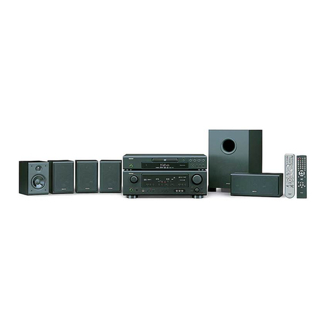
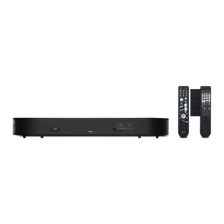
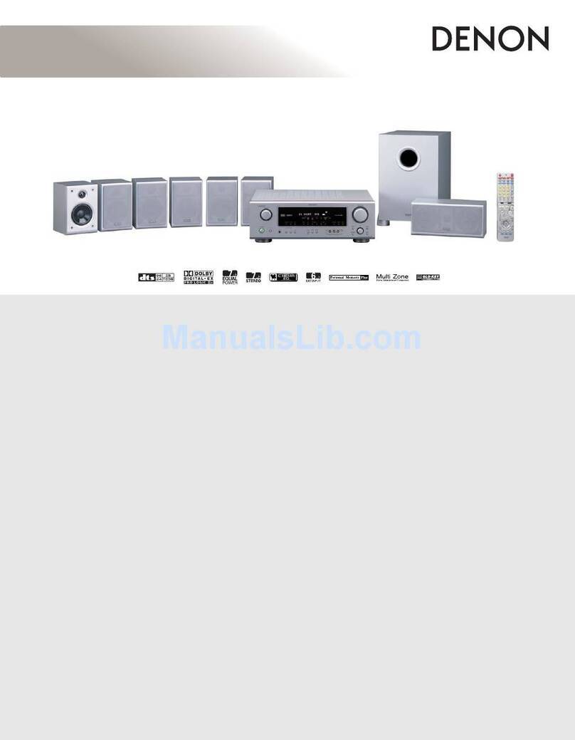
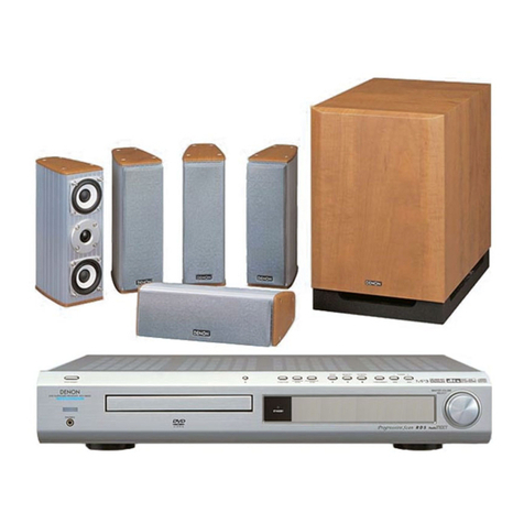
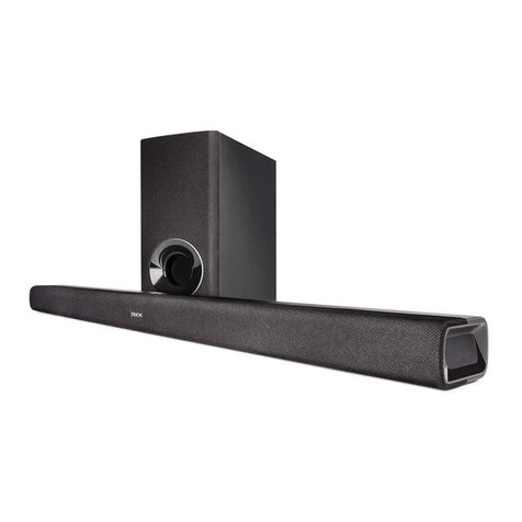
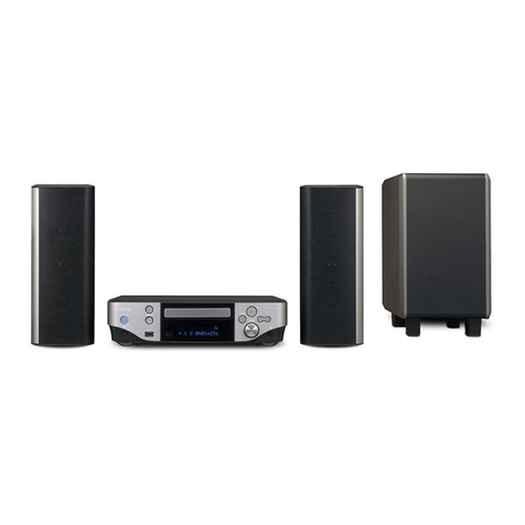
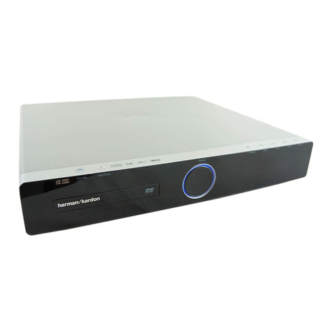
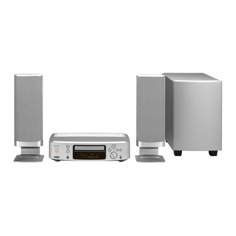
Denon DHT FS5 - X-SPACE Surround System Home Theater Speaker... User manual

Denon Brand Company, D&M Holdings lnc.
e
●For purposes of improvement, specifications and
design are subject to change without notice.
●Please use this service manual with referring to the
operating instructions without fail.
●Some illustrations using in this service manual are
slightly different from the actual set.
注 意
サービスをおこなう前に、このサービスマニュアルを
必ずお読みください。本機は、火災、感電、けがなど
に対する安全性を確保するために、さまざまな配慮を
おこなっており、また法的には「電気用品安全法」に
もとづき、所定の許可を得て製造されております。
従ってサービスをおこなう際は、これらの安全性が維
持されるよう、このサービスマニュアルに記載されて
いる注意事項を必ずお守りください。
●本機の仕様は性能改良のため、予告なく変更すること
があります。
●補修用性能部品の保有期間は、製造打切後 8 年です。
●修理の際は、必ず取扱説明書を参照の上、作業を行っ
てください。
●本文中に使用しているイラストは、説明の都合上現物
と多少異なる場合があります。
X0366V.02 DE/CDM 0802
SERVICE MANUAL
HOME THEATER SYSTEM
MODEL JP E3 E2 EK E2A E1C E1K EUT
DHT-FS5
333
Ver. 2
Please refer to the
MODIFICATION NOTICE.

2
DHT-FS5
Please heed the points listed below during servicing and inspection.
◎Heed the cautions!
Spots requiring particular attention when servicing, such as
the cabinet, parts, chassis, etc., have cautions indicated on
labels or seals. Be sure to heed these cautions and the cau-
tions indicated in the handling instructions.
◎Caution concerning electric shock!
(1) An AC voltage is impressed on this set, so touching inter-
nal metal parts when the set is energized could cause
electric shock. Take care to avoid electric shock, by for ex-
ample using an isolating transformer and gloves when
servicing while the set is energized, unplugging the power
cord when replacing parts, etc.
(2)There are high voltage parts inside. Handle with extra care
when the set is energized.
◎
Caution concerning disassembly and assembly!
Though great care is taken when manufacturing parts from
sheet metal, there may in some rare cases be burrs on the
edges of parts which could cause injury if fingers are moved
across them. Use gloves to protect your hands.
◎Only use designated parts!
The set's parts have specific safety properties (fire resis-
tance, voltage resistance, etc.). For replacement parts, be
sure to use parts which have the same properties. In particu-
lar, for the important safety parts that are marked ! on wiring
diagrams and parts lists, be sure to use the designated parts.
◎Be sure to mount parts and arrange the
wires as they were originally!
For safety reasons, some parts use tape, tubes or other insu-
lating materials, and some parts are mounted away from the
surface of printed circuit boards. Care is also taken with the
positions of the wires inside and clamps are used to keep
wires away from heating and high voltage parts, so be sure to
set everything back as it was originally.
◎Inspect for safety after servicing!
Check that all screws, parts and wires removed or discon-
nected for servicing have been put back in their original posi-
tions, inspect that no parts around the area that has been
serviced have been negatively affected, conduct an insulation
check on the external metal connectors and between the
blades of the power plug, and otherwise check that safety is
ensured.
(Insulation check procedure)
Unplug the power cord from the power outlet, disconnect the
antenna, plugs, etc., and turn the power switch on. Using a
500V insulation resistance tester, check that the insulation re-
sistance between the terminals of the power plug and the ex-
ternally exposed metal parts (antenna terminal, headphones
terminal, microphone terminal, input terminal, etc.) is 1MΩor
greater. If it is less, the set must be inspected and repaired.
Concerning important safety parts
Many of the electric and structural parts used in the set have
special safety properties. In most cases these properties are
difficult to distinguish by sight, and using replacement parts
with higher ratings (rated power and withstand voltage) does
not necessarily guarantee that safety performance will be pre-
served. Parts with safety properties are indicated as shown
below on the wiring diagrams and parts lists is this service
manual. Be sure to replace them with parts with the designat-
ed part number.
(1) Schematic diagrams ... Indicated by the ! mark.
(2) Parts lists ... Indicated by the ! mark.
Using parts other than the designated parts
could result in electric shock, fires or other
dangerous situations.
SAFETY PRECAUTIONS
The following check should be performed for the continued protection of the customer and service technician.
LEAKAGE CURRENT CHECK
Before returning the unit to the customer, make sure you make either (1) a leakage current check or (2) a line to chassis
resistance check. If the leakage current exceeds 0.5 milliamps, or if the resistance from chassis to either side of the power
cord is less than 460 kohms, the unit is defective.
CAUTION
CAUTION
サービス、点検時にはつぎのことにご注意願います。
◎注意事項をお守りください!
サービスのとき特に注意を必要とする個所についてはキャ
ビネット、部品、シャーシなどにラベルや捺印で注意事項を
表示しています。これらの注意書きおよび取扱説明書などの
注意事項を必ずお守りください。
◎感電に注意!
(1) このセットは、交流電圧が印加されていますので通電時
に内部金属部に触れると感電することがあります。従っ
て通電サービス時には、絶縁トランスの使用や手袋の着
用、部品交換には、電源プラグを抜くなどして感電にご
注意ください。
(2) 内部には高電圧の部分がありますので、通電時の取扱に
は十分ご注意ください。
◎分解、組み立て作業時のご注意!
板金部品の端面の『バリ』は、部品製造時に充分管理をして
おりますが、板金端面は鋭利となっている箇所が有りますの
で、部品端面に触れたまま指を動かすとまれに怪我をする場
合がありますので十分注意して作業して下さい。手の保護の
ために手袋を着用してください。
◎指定部品の使用!
セットの部品は難燃性や耐電圧など安全上の特性を持った
ものとなっています。従って交換部品は、使用されていたも
のと同じ特性の部品を使用してください。特に配線図、部品
表に!印で指定されている安全上重要な部品は必ず指定の
ものをご使用ください。
◎部品の取付けや配線の引きまわしは、
元どおりに!
安全上、テープやチューブなどの絶縁材料を使用したり、プ
リント基板から浮かして取付けた部品があります。また内部
配線は引きまわしやクランパーによって発熱部品や高圧部
品に接近しないように配慮されていますので、これらは必ず
元どおりにしてください。
◎サービス後は安全点検を!
サービスのために取り外したねじ、部品、配線などが元どお
りになっているか、またサービスした個所の周辺を劣化させ
てしまったところがないかなどを点検し、外部金属端子部
と、電源プラグの刃の間の絶縁チェックをおこなうなど、安
全性が確保されていることを確認してください。
(絶縁チェックの方法)
電源コンセントから電源プラグを抜き、アンテナやプラグな
どを外し、電源スイッチを入れます。500V 絶縁抵抗計を用
いて、電源プラグのそれぞれの端子と外部露出金属部[アン
テナ端子、ヘッドホン端子、マイク端子、入力端子など]と
の間で、絶縁抵抗値が1 MΩ 以上であることを確認してく
ださい。この値以下のときはセットの点検修理が必要です。
安全上重要な部品について
本機に使用している多くの電気部品、および機構部品は安全
上、特別な特性を持っています。この特性はほとんどの場合、
外観では判別つきにくく、またもとの部品より高い定格(定
格電力、耐圧)を持ったものを使用しても安全性が維持され
るとは、限りません。安全上の特性を持った部品は、この
サービスマニュアルの配線図、部品表につぎのように表示し
ていますので必ず指定されている部品番号のものを使用願
います。
(1) 配線図…!マークで表示しています。
(2) 部品表…!マークで表示しています。
指定された部品と異なるものを使用した場合に
は、感電、火災などの危険を生じる恐れがあり
ます。
注 意
注 意
3
DHT-FS5
DIMENSION
DHT-FS5
Without feet : 750 (W) x 118 (H) x 138 (D) mm
With 35mm (height) feet(JP) : 750 (W) x 140 (H) x 138 (D)mm
With 25mm (height) feet(E2,E3) : 750 (W) x 130 (H) x 138 (D)mm

4
DHT-FS5
ワイヤー整形図
調整や部品の交換等により、ワイヤー類の結束をはずしたり移
動させた場合には、それらの作業が完了した時点でワイヤーの
整形をおこなってください。正しく整形されてないとノイズ発
生の原因となることがあります。
1. AMPLIFIERP.W.BUNIT部
(1) qCABLEXARR-12L135 を 4P/5P/6P コネクタよりの位置
でコードが広がらないようクランプバンドで固定する。
2. TOTALCOVERREARASSY部
(1) w5PPH-PHCORD を Cover-Rear のリブのスリットに通
してワイヤーを整形する。
WIRE ARRANGEMENT
If wire bundles are untied or moved to perform adjustment or
parts replacement etc., be sure to rearrange them neatly as
they were originally bundled or placed afterward.
Otherwise, incorrect arrangement can be a cause of noise
generation.
1. AMPLIFIER P.W.B UNIT
(1) qFasten the CABLE XARR-12 L135 with a clamp band
at the position from the 4P/5P/6 connector .For the CA-
BLE XARR-12 L135 is not extended.
2. TOTAL COVER REAR ASSY
(1) Pass the 5P PH-PH CORD(w) through the slit of rib on
the Cover-Rear, and arrange the wire.
①
②

5
DHT-FS5
(2) e5PPH-PHCORD を Plate-Shielding にクランプバンド
で3ヶ所固定する。Foam を2ヶ所貼付け固定する。
(3) rCABLEVH-3L125 を Cover-Rear のリブの 2ヶ所のス
リットに通してワイヤーを整形する。
(4) tCABLEXARR-12L135 を Cover-Rear にクランプバンド
で固定する。
(2) Fasten the 5P PH-PH CORD(e) three times on the
Plate-Shielding with a clamp band, and paste the Foam
twice on.
(3) rPass the CABLE VH-3 L125(r) through twice slits of
rib on the Cover-Rear and arrange the wire.
(4) Fasten the CABLE XARR-12 L135(t) on the Cover-
Rear with the clamp band.
Foam
㽴
④
⑤

6
DHT-FS5
(5) yCABLEXARR-12L135 が Cover-Rear の凹部からはみ出
さないようにワイヤーを整形する。
(6) u5PPH-PHCORD を Cover-Rear のリブのスリットに通
し、18PFFC の内側を通して 1305 へ接続する。
(7) iCABLEEH-2L100をCover-Rearの基板固定用リブの外
側に沿わせ、Cover-Rear のリブのスリットに通してワイ
ヤーを整形する。
(5) Arrange the wire for the CABLE XARR-12 L135 is not
hung out of concave of Cover-Rear.
(6) Pass the 5P PH-PH CORD(u) through slit of rib on the
Cover-Rear, and inside of 18P FFC then connect to
1305.
(7) CABLE EH-2 L100 is along the outside of rib for fastening
the circuit board, then pass it through the slit of rib on the
Cover-Rear.
⑥
㽹
㪈㪊㪇㪌
㽸
㽹
Diagonal

7
DHT-FS5
各部のはずしかた
(組み立てるときは、逆の順序でおこなってください。)
1. ネットのはずしかた
(1) 先端の細いマイナスドライバー等を本体底面の穴へ差
し込み、フロント側へネットを押し出す(3ヶ所)。
(2) ネットを矢印の方向へはずす。
2. リアパネルのはずしかた
(1) 背面よりネジを 12 本はずす。
(2) リアパネルを矢印の方向へはずす。
3. DISPLAY 基板のはずしかた
(1) フロント面よりネジを 3 本はずす。
(2) FRONT 基板を矢印の方向へはずす。
(3) DISPLAY 基板上のコネクタをはずす。
DISASSEMBLY
(Follow the procedure below in reverse order when reassem-
bling.)
1. Nets
(1) A thin minus driver in the point etc. are inserted in the
hole of the main body bottom, and the net is pushed out
to the front side (three places).
(2) Detach the Net as shown in the arrow direction.
2. Rear Panel
(1) Remove 12 screws on the rear.
(2) Detach the Rear Panel as shown in the arrow direction.
3. Display P.W.B.
(1) Remove 3 screws on the front.
(2) Detach the FRONT P.W.B. as shown in the arrow direc-
tion.
(3) Disconnect the connectors on the DISPLAY P.W.B..

8
DHT-FS5
4. ボトムカバーのはずしかた
bボトムカバーをはずす前に必ず DISPLAY 基板をはずす。
(1) 本体底面よりネジを 16 本はずす。
(2) ボトムカバーを矢印の方向へはずします。
5. シールドプレートのはずしかた
(1) シールドプレート上のネジを 11 本はずす。(b印ネジ
のみ種類が異なる)
(2) シールドプレートを持ち上げ、SMPS 基板、SIGNAL 基
板上の二箇所のコネクターをはずす。
6. SMPS 基板のはずしかた
(1) SMPS 基板上のネジを 3 本はずす。
(2) AC コードブッシュを矢印方向へずらしてはずす。
(3) SMPS 基板を矢印の方向へはずす。
4. Bottom cover
bRemove the DISPLAY P.W.B. without fail. Before the bottom
cover is removed.
(1) Remove 16 screws on the bottom.
(2) Detach the Bottom cover as shown in the arrow direction.
5. Shield Plate
(1) Remove 11 screws fixing the Shield Plate.(Only the b
sign screw is different the kind. )
(2) Lift up the Shield Plate and disconnect the 2 connectors
on the SMPS and SIGNAL P.W.B unit.
6. SMPS P.W.B.
(1) Remove the 3 screws on the SMPS P.W.B.
(2) Detach the AC cord bush in the direction of the arrow.
(3) Detach the SMPS P.W.B. as shown in the arrow direction
.
b
Connector
Connector

9
DHT-FS5
(4) SMPS 基板上のコネクタをはずす。
b組み立て時には、AC コードの側線が写真のようになるこ
と。
7. SIGNAL 基板のはずしかた
(1) SIGNAL 基板上の FFC をはずす。
(2) 矢印 A の方向へ SIGNAL 基板をずらした後、矢印 B の
方向へ基板を裏返す。
(4) Disconnect the connector on the SMPS P.W.B..
.
bWhen assembling, lateral code of AC code becomes as
shown in the photograph.
7. SIGNAL P.W.B.
(1) Disconnect the FFC on the SIGNAL P.W.B..
(2) Move the SIGNAL P.W.B. in the direction of the arrow A.
Then turn over the SIGNAL P.W.B. in the direction of the
arrow B.
A
B

10
DHT-FS5
(3) FFC 二箇所をはずす。
8. AMP 基板のはずしかた
(1) リアパネルのねじを 2 本はずす。
(2) AMP 基板上のネジを2本はずす。
(3) 金具の止めネジをはずす。
(4) 金具を 2 個はずす。
(3) Disconnect the 2 FFC on the SIGNAL P.W.B..
8. AMP P.W.B.
(1) Remove the 2 screws on the rear panel.
(2) Remove the 2 screws fixing the AMP P.W.B..
(3) Remove the metal fitting fixation screw.
(4) Remove the 2 metal fittings.

11
DHT-FS5
(5) AMP 基板を持ち上げ、基板上の 2 箇所のコネクタをは
ずす。
(6) AMP 基板を 90°に立て、基板上 4 箇所のコネクタをは
ずす。
9. コネクタ基板のはずしかた
(1) リアパネル下面のネジを 5 本はずす。
(5) Lift up the AMP P.W.B. then disconnect 2 connectors fix-
ing the AMP P.W.B..
(6) Stand the AMP P.W.B. vertically and disconnect the 4
connectors on the AMP P.W.B..
9. Connector P.W.B.
(1) Disconnect 5 screws lower side of the rear panel.

12
DHT-FS5
(2) コネクタ基板を矢印の方向へはずす。
(3) コネクタ基板上各 1 箇所のコネクタと FFC をはずす。
10.アルミプレートのはずしかた
(1) アルミプレート固定ネジをはずす。
(2) アルミプレートを矢印の方向へはずす。
11.シールドプレートのはずしかた
(1) シールドプレートを矢印の方向へはずす。
(2) Detach the Connector P.W.B. as shown in the arrow di-
rection.
(3) Disconnect the each 1 connector and the FFC on the
Connector P.W.B..
10.Aluminum Plate
(1) Remove the Aluminum plate fixation screw.
(2) Detach the Aluminum Plate as shown in the arrow direc-
tion.
11.Shield Plate
(1) Detach the shield plate in the direction of the arrow.

13
DHT-FS5
12.スピーカーユニットのはずしかた
(1) 各スピーカーユニット4本の固定ネジをはずす。
(2) ファストン端子をはずす。(ファストン端子をはずす場
合は、先端の細いマイナスドライバー等で矢印の突起
を押しながら引き抜く)
(3) スピーカーユニットを前方にはずす。
12.Each Speaker Unit
(1) Remove 4 screws fixing the each Speaker Unit.
(2) Disconnect the faston terminal.(If the faston terminal is
disconnected, keep on pushing the projection of the ar-
row. By the point of the minus driver etc. and pull the Fas-
ten terminal.)
(3) Detach the Speaker Unit as shown in the arrow direction.
Center Speaker Unit Surround Speaker Unit
Keep on pushing the projection, and
pull the faston terminals
突起を押しながら引き抜く
Red circle partial closeup

14
DHT-FS5
CAUTION IN SERVICING
Initializing DHT-FS5
DHT-FS5 initialization should be performed when Signal P.W.B.
is replaced.
1. "SETUP" button of remote control is pushed for two seconds
or more in the state of power supply ON.
2. "rE" is displayed when becoming an initialization mode.
*The µcom is initialized.
Note:・All user settings (Details in listening room,Set value
of tone quality and various modes)will be lost and this
factory setting will be recovered when this initializa-
tion mode.
So make sure to memorize your setting for restoring
after the initialization.
サービス時の注意事項
本機の初期化について
Signal 基板を交換した場合は、本機の初期化を行って下さい。
1. 電源 ON 状態でリモコンの " 設定 " ボタンを 2 秒以上押す。
2. 初期設定モードになると、"rE" を表示します。
*マイコンが初期化されます。
注意 :・初期化を行うとお客様が設定した内容 ( リスニング
ルームの詳細、音質や各種モードの設定値 ) が工場
出荷状態に戻りますので、あらかじめ設定内容を控
えておき初期化後に再設定してください。

15
DHT-FS5
TEST MODE
1. INTRODUCTION
The DHT-FS5 has 2 test modes.
1) BYPASS mode : for electrical measurements
2) CERTIFICATION mode: for Dolby, DTS and AAC certification tests
2. HOW TO ENTER THE TEST MODES
Perform following actions:
1) Unplug the AC cord during the power turned on.
2) Pressing the set with the mains switch, plug the AC cord into a power outlet.
3) Release the main switch after the display lights.
4) If you want to enter "BYPASS mode":
Press the "TV(d1)" button on the remote control unit within 2 sec the display will show "bp".
If you want to enter "CERTIFICATION mode":
Press the "DVD(d2)" button on the remote control unit within 2 sec the display will show "CE"
3. HOW TO LEAVE THE TEST MODES
1) Switch off the set (with the mains switch) and switch on again
4. BYPASS MODE
4.1. Configuration
- The multichannel decoder is forced to PCM
- The X-space surround encoder is disabled
テストモード
1. はじめに
DHT-FS5 には 2 つのテストモードがあります。
1)BYPASSモード : 電気的測定用
2)CERTIFICATIONモード : DOLBY、DTS、AACの承認テスト用
2. テストモードへの入り方
以下のように操作する。
1) DHT-FS5 が電源 ON状態で AC コードを抜く。
2) 電源ボタンを押しながら AC コードを接続する。
3) ディスプレイが点灯したら、電源ボタンを離す。
4) "BYPASSモード " にする時は、2 秒以内にリモコンの" テレビ(d1)"ボタンを押す。
ディスプレイに"bp"と表示される。
"CERTIFICATIONモード " にする時は、2 秒以内にリモコンの"DVD(d2)"ボタンを押す。
ディスプレイに"CE"と表示される。
3. テストモードの終わり方
1)DHT-FS5 の電源ボタンを押して OFF にし、再度 ON にする。
4. BYPASSモード
4.1. 設定
-マルチチャンネル処理は PCM
-X-spacesurround 処理機能は無効

16
DHT-FS5
4.2. Switching the bass manager
When entering "BYPASS mode", the bass manager is set for "configuration 1".
It is possible to switch the bass manager between "off" and "configuration 1". This can be selected with the "SETUP" button
on the remote control unit. The display will show "oF" or "C1".
4.3. Switching on/off individual amplifier channels
When entering the "BYPASS mode", all output channels will be active.
However, for certain tests it is required to switch off one or more output channels.
Different speaker modes can be selected with the "SDB" button on remote control unit.
When pressing the "SDB" button, you will see the output channels which are active. By default you will see "AL" which means
that all speakers are active. By pressing "SDB" several times, you can switch off different output channels:
Speaker modes:
AL
1
2
3
4
5
6
"1" - "5" correspond to F1-F5 of the speaker
"6" is the PRE OUT
5. CERTIFICATION MODE
5.1. Configuration
- The X-space surround encoder is switched off
The complete signal routing is shown in below diagrams:
5.2. Switching the bass manager
When entering "certification mode", the bass manager is set for "configuration 1".
It is possible to switch the bass manager between "off" and "configuration 1".
This can be selected with the "SETUP" button of Remote Controller. The display will show alternatively "oF" and "C1".
4.2. ベースマネージメントの切り替え
"BYPASSモード " に入ると、ベースマネージメントは "CF1" に設定される。
リモコンの " 設定 " ボタンでベースマネージメントを、"OFF"または"CF1"に切り替えることができる。
"oF"( ベースマネージメント OFF)または"C1"( ベースマネージメント CF1) が表示される。
4.3. 各アンプチャンネルの ON/OFF 切り替え
"BYPASSモード " に入ると、全チャンネルの出力が有効になる。ただし、ある種のテストにおいては、いくつかの出力
チャンネルを OFF に切り替える必要がある。
リモコンの " 重低音 "ボタンでスピーカ出力チャンネルを選択できる。" 重低音 " ボタンを押している間、有効な出力チャ
ンネルを確認できる。
初めに全スピーカーが有効であることを示す "AL" が表示される。" 重低音 "ボタンを押す毎に , 下記の q〜uのようにス
ピーカー出力チャンネルを OFF に切り替えられる。
スピーカーモード :
①AL
②1
③2
④3
⑤4
⑥5
⑦6
"1"〜 "5" はスピーカのF1 〜 F5 に対応する。
"6"は PRE OUT
5. CERTIFICATIONモード
5.1. 設定
-X-spacesurround 処理機能は OFF
全体の信号の流れを下図に示す。
5.2. ベースマネージメントの切り替え
"CERTIFICATIONモード " に入ると、ベースマネージメントは"CF1"に設定される。
リモコンの " 設定 " ボタンでベースマネージメントを、"OFF"または"CF1"に切り替えることができる。
"oF"( ベースマネージメント OFF)と"C1"( ベースマネージメント CF1) のどちらかが表示される。

17
DHT-FS5
ERROR CODES
1. DIAGNOSTICS ERRORS
The set performs a system diagnostic test after power on. All peripheral ICs are checked. If one or more ICs are failing, the
display will flash the following message:
Er
When pressing the mains switch, the display will show which IC is failing. Multiple ICs might be indicate:
1 = M24C02
2 = AK4113
3 = TAS5086
4 = (not used)
5 = M25P20
6 = DSP
2. AMPLIFIER SHUT-DOWN ERROR
When amplifier shut-down occurs, following error will flash:
C1
3. AMPLIFIER DC ERROR
When amplifier DC error occurs, following error will flash:
C2
4. AMPLIFIER OVER TEMPERATURE ERROR
When amplifier is too hot, following error will flash:
C3
エラーコード
1.自己診断エラー
DHT-FS5 は電源を ON にすると自己システム診断を行う。全ての周辺 IC を診断し、IC に不都合を検出すると、
Erを点滅表示する。
Er
フロントパネルの電源ボタンを押すと、不都合のあった IC が下記のように表示される。
複数の IC に不都合があった場合は、該当する IC が同時に表示される。
1=M24C02
2=AK4113
3=TAS5086
4=(not used)
5=M25P20
6=DSP
2.アンプシャットダウンエラー
アンプがシャットダウンした場合、C1 が点滅表示する。
C1
3.アンプDC エラー
アンプに DC エラーが発生した場合、C2 が点滅表示する。
C2
4.アンプ温度超過エラー
アンプが過熱した場合、C3 が点滅表示する。
C3

18
DHT-FS5
TROUBLE SHOOTING トラブルシューティング
1.Power not turn on
N.G
O.K.
N.G
O.K.
N.G N.G
O.K. O.K.
N.G
2.DISPLAY(7Seg-LED、Mode-LED) doesn't show
N.G
O.K.
N.G
O.K. O.K.
Check the Soldering.
connector 1107:3,8pin on FRONT UNIT
connector 1302:3,8pin on SIGNAL UNIT
Check the Power Supply Voltages.
FRONT UNIT
+3.3V[connector 1107:3pin](Voltage value:3.3V)
+5.1V[connector 1107:8pin](Voltage value:5.1V)
Check the Communication waveform for µCOM.
FRONT UNIT
CP[connector 1107:4pin]
DA[connector 1107:5pin]
STR[connector 1107:6pin]
Communication O.K.?
Check the Soldering.
connector 1107:4-6pin on FRONT UNIT
connector 1302:4-6pin on SIGNAL UNIT
FRONT UNIT is replaced.
Check the FUSE condition.
PSU UNIT
F1
Check the Power Supply Voltages.
PSU UNIT
+5.1V[connector CN3(J2):1pin](Voltage
value:5.1V)
PSU UNIT is replaced.
SIGNAL UNIT is replaced.
Check the Power On signal.
PSU UNIT
STBY[connector CN3(J2):3pin]
Is the "H" signal inputted, pressing set with the main
switch?
Check the Power Supply Voltages.
PSU UNIT
+38V[connector CN2(J3):1pin](Voltage value:38V)
+16V[connector CN2(J3):3pin](Voltage value:14V)
Check the POWER KEY signal.
SIGNALޓUNIT
KEY[connector 1302:7pin]
Is the "H-Pulse" signal inputted, pressing set with
the main switch?
SIGNAL UNIT is replaced.
FRONT UNIT is replaced.
PSU UNIT is replaced.
1.電
源
入ら
ず
N.
G
O
.K.
N.G
O
.K.
N.
G
N.
G
O
.K.
O
.K.
N.G
2.DISPLA
Y
(7Seg-LED、Mode-LED)表示せず
N.
G
O
.K.
N.
G
O
.K.
O
.K.
半田付けを確認
・コネクタ1107:3,8pinonFRONTUNIT
・コネクタ1302:3,8pinonSIGNALUNIT
電源電圧確認
FRONTUNIT
・+3.3V[コネクタ1107:3pin](電圧値:3.3V)
・+5.1V[コネクタ1107:8pin](電圧値:5.1V)
マイコン通信波形の確認
FRONTUNIT
・CP[コネクタ1107:4pin]
・DA[コネクタ1107:5pin]
・STR[コネクタ1107:6pin]
通信 O.K.?
半田付けを確認
・コネクタ1107:4-6pinonFRONTUNIT
・コネクタ1302:4-6pinonSIGNALUNIT
FRONTUNITを交換する
ヒューズ確認
PSUUNIT
・F1
電源電圧確認
PSUUNIT
・+5.1V[コネクタCN3(J2):1pin](電圧値:5.1V)
PSUUNITを交換する
SIGNALUNITを交換する
POWERON信号の確認
PSUUNIT
・STBY[コネクタCN3(J2):3pin]
電源ボタンを押したとき"H"になるか?
電源電圧確認
PSUUNIT
・+38V[コネクタCN2(J3):1pin](電圧値:38V)
・+16V[コネクタCN2(J3):3pin](電圧値:14V)
POWERKEY信号の確認
SIGNAL UNIT
・KEY[コネクタ1302:7pin]
電源ボタンを押したとき"H-Pulse"になるか?
SIGNALUNITを交換する
FRONTUNITを交換する
PSUUNITを交換する

19
DHT-FS5
3.Error Code is displayed
(1)."c_" is displayed.
①
②
N.G
O.K.
N.G
O.K.
(2)."Er" is displayed.(IC failing)
①
②
Check the Power Supply Voltages.
PSU UNIT
+38V[connector CN2(J3):1pin](Voltage value:38V)
+16V[connector CN2(J3):3pin](Voltage value:14V)
AMP UNIT is replaced.
PSU UNIT is replaced.
AMP UNIT is replaced.
SIGNAL UNIT is replaced.
Check the display when the ON/STANDBY button is
pressed.
"1":M24C02 error,
"2":AK4113 errer, →①
"5":M25P20 error,
"6":DSPC56371 error
"3":TAS5086 error →②
Check the indication of DISPLAY.
"c1"(Amplifirer shut down error)→①
"c2"(Amplifirer DC error)→②
Check the Power Supply Voltages.
AMP UNIT
+38V[connector 1700:1pin](Voltage value:38V)
+16V[connector 1700:3pin](Voltage value:14V)
Check the Soldering.
connector 1700:1pinޓon AMP UNIT
connector 1700:3pinޓon AMP UNIT
AMP UNIT is replaced.
3.エラーコードの表示がでる
(
1
)
.
"
c_
"
表示
①
②
N
.
G
O
.K.
N
.
G
O
.K.
(2)."Er"表示(ICfailing)
①
②
電源電圧確認
PSUUNIT
・+38V[コネクタCN2(J3):1pin](電圧値:38V)
・+16V[コネクタCN2(J3):3pin](電圧値:14V)
AMPUNITを交換する
PSUUNITを交換する
AMPUNITを交換する
SIGNALUNITを交換する
ON/STANDBYボタンを押した時の表示を確認する。
"1":M24C02error,
"2":AK4113errer, →①
"5":M25P20error,
"6":DSPC56371error
"3":TAS5086error →②
DISPLAYの表示を確認する。
"c1"(Amplifirershutdownerror)→①
"c2"(AmplifirerDCerror)→②
電源電圧確認
AMPUNIT
・+38V[コネクタ1700:1pin](電圧値:38V)
・+16V[コネクタ1700:3pin](電圧値:14V)
半田付けを確認
・コネクタ1700:1pin onAMPUNIT
・コネクタ1700:3pin onAMPUNIT
AMPUNITを交換する

20
DHT-FS5
4.No sound is output
(1).Analog(An) input
N.G
O.K. O.K.
【
A
】
【
B
】
(2)TV(d1) input
N.G
O.K. O.K.
【
A
】
【
B
】
(3).DVD(d2) input
N.G
O.K. O.K.
【
A
】
【
B
】
(4).Digital(D) input
N.G
O.K. O.K.
【
A
】
【
B
】
Check the Digital Audio output to SIGNAL UNIT
SIGNAL UNIT
OPT1[connector 1200:13pin]
Check the Soldering.
OPT Receiver 7000:1pin on connector UNIT
connector 1005:13pin on connector UNIT
connector 1200:13pin on SIGNAL UNIT
Check the Digital Audio output to SIGNAL UNIT
SIGNAL UNIT
DIG1[connector 1200:11pin]
Check the Soldering.
Jack 1006:2pin on connector UNIT
connector 1005:11pin on connector UNIT
connector 1200:11pin on SIGNAL UNIT
Check the Digital Audio output to SIGNAL UNIT
SIGNAL UNIT
OPT2[connector 1200:15pin]
Check the Soldering.
OPT Receiver 7001:1pin on connector UNIT
connector 1005:15pin on connector UNIT
connector 1200:15pin on SIGNAL UNIT
Check the Analog Audio output to SIGNAL UNIT
SIGNAL UNIT
TV_L[connector 1200:1pin]
TV_R[connector 1200:3pin]
Check the Soldering.
Jack1000:1-2pin on connector UNIT
connector 1005:1,3pin on connector UNIT
connector 1200:1,3pin on SIGNAL UNIT
4.音声出力せず
(
1
)
.ア
ナ
ロ
グ
(
An
)
入力
N.
G
O
.K.
O
.K.
【
A
】
へ
【
B
】
へ
(
2
)
T
V
(
d
1
)
入力
N.
G
O
.K.
O
.K.
【
A
】
へ
【
B
】
へ
(
3
)
.DVD
(
d
2
)
入力
N.
G
O
.K.
O
.K.
【
A
】
へ
【
B
】
へ
(
4
)
.
デジタル
(
D
)
入力
N.
G
O
.K.
O
.K.
【
A
】
へ
【
B
】
へ
SIGNALUNITへのディジタルオーディオ出力確認
SIGNALUNIT
・OPT1[コネクタ1200:13pin]
半田付けを確認
・OPTReceiver7000:1pinonCONNECTORUNIT
・コネクタ1005:13pinonCONNECTORUNIT
・コネクタ1200:13pinonSIGNALUNIT
SIGNALUNITへのディジタルオーディオ出力確認
SIGNALUNIT
・DIG1[コネクタ1200:11pin]
半田付けを確認
・Jack1006:2pinonCONNECTORUNIT
・コネクタ1005:11pinonCONNECTORUNIT
・コネクタ1200:11pinonSIGNALUNIT
SIGNALUNITへのディジタルオーディオ出力確認
SIGNALUNIT
・OPT2[コネクタ1200:15pin]
半田付けを確認
・OPTReceiver7001:1pinonCONNECTORUNIT
・コネクタ1005:15pinonCONNECTORUNIT
・コネクタ1200:15pinonSIGNALUNIT
SIGNALUNITへのアナログオーディオ出力確認
SIGNALUNIT
・TVL[コネクタ1200:1pin]
・TVR[コネクタ1200:3pin]
半田付けを確認
・Jack1000:1-2pinonCONNECTORUNIT
・コネクタ1005:1,3pinonCONNECTORUNIT
・コネクタ1200:1,3pinonSIGNALUNIT
Other manuals for DHT FS5 - X-SPACE Surround System Home Theater Speaker...
5
Table of contents
Other Denon Home Theater System manuals

Denon
Denon S-52 Dimensions

Denon
Denon S-302 User manual

Denon
Denon AVR-2309CI User guide

Denon
Denon DHT-485DV Assembly instructions

Denon
Denon ADV-1000 User manual

Denon
Denon DHT-391XP User manual

Denon
Denon S-102 User manual

Denon
Denon DHT-485DV User manual

Denon
Denon DHT-485XP Instruction Manual

Denon
Denon ADV-700 User manual