DentalEZ Core User manual

CORETM Delivery Unit
Console Mount
User Manual

i
www.DentalEZ.com 866-DTE-INFO
i
DentalEZ®Equipment
PN: 2717-269C
Table of Contents
Section I Introduction
Product Overview ............................................... 1
Console Mounted Unit Features........................2
Dimensions ........................................................ 3
Specications .................................................... 4
Classications ................................................... 5
Explanation of Symbols & Signs ...................... 5
Safety Precautions............................................ 6
Section II Preinstallation
Packaging .......................................................... 9
Unit Placement ................................................. 10
Utility Service Center (USC).............................10
Section III Installation
Console Adaptor Mount................................... 13
Console ............................................................. 15
Assistant’s Arm (Optional)............................... 16
Assistant’s Instrumentation............................ 17
Cuspidor (Optional) ..........................................18
Delivery Head Arm Assembly.......................... 19
Light Post (Optional) ........................................ 19
Fiber Optic Electrical (Optional) ..................... 20
Handpiece Tubing ........................................... 20
Finalizing USC Installation ............................... 21
Power Module (Optional)................................. 23
Section IV Testing
Delivery System............................................... 25
Syringe ............................................................. 26
Foot Control and Handpieces......................... 26
Cuspidor........................................................... 28
Other Optional Features.................................. 30
Section V Operation
Delivery Head.................................................... 31
Syringe ............................................................. 32
Foot Control ..................................................... 32
Assistant’s Vacuum Accessories................... 33
Clean Water System........................................ 33
Cuspidor........................................................... 34
Section VI Care
Cleaning ........................................................... 35
Disinfecting...................................................... 36
Section VII User Service Information
Troubleshooting .............................................. 37
Service Instruction .......................................... 40
Disposal of Equipment.................................... 40
Section VIII Parts Lists/Diagrams
Utility Service Center ....................................... 41
Assistant’s Arm (Optional)............................... 41
CORE Delivery Head ........................................ 42
Touch Pads....................................................... 43
Console ............................................................ 44
Simplicity Cuspidor (Optional)........................ 45
Galaxy Cuspidor (Optional) ............................. 46
Foot Control ..................................................... 47
Air/Water Syringe ............................................ 47
HVE Nozzle....................................................... 48
Saliva Ejector Nozzle....................................... 48
EMC Information.............................................. 49
Limited Warranty.............................................. 51

www.DentalEZ.com 866-DTE-INFO
ii
CORETM Console Mounted Unit
PN: 2717-269C
1
www.DentalEZ.com 866-DTE-INFO
1
DentalEZ®Equipment
PN: 2717-269C
This manual contains installation, operation and
care instructions, and user service information
for the DentalEZ® CORE™ Console Mounted Unit
(CMU).
The CORE CMU is intended to be used by trained
professional dental care personnel only, as an
interface device to connect the dental operatory
hand instruments to the appropriate supply utility
such as air, water, vacuum, drain and electrical.
It functions as a system management device
that provides a method of operating the hand
instruments from a single control input device.
The CORE CMU is manufactured to be used
with a dental chair that supports a patient in
a reclined seated position. Operators will be
positioned around the patient’s head as required
for optimum access for the specic procedure
being performed. The delivery unit positions the
handpieces for the optimum presentation to the
operator.
The CORE CMU is designed to provide trouble-
free service when installed, operated and cared
for according to the procedures set forth in this
manual.
To ensure proper installation, carefully
read all of the instructions contained in
this manual, paying close attention to all
warnings, cautions and notes.
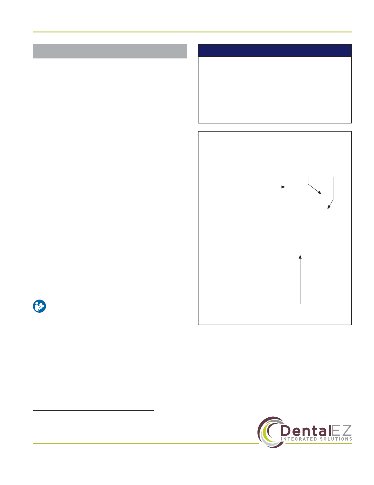
Before starting installation procedures, review
the illustration to become familiar with the
components of the CORE CMU (Figure 1).
After the CORE CMU is installed, review the
features, operation procedures, and care
guidelines with the doctor’s sta.
Leave this manual in the doctor’s oice.
Section I Introduction
Product Overview
• Installation by an authorized
DentalEZ dealer service technician is
recommended.
• For any questions about an order, please
contact a DentalEZ Equipment customer
service representative at 866-DTE-INFO.
NOTICE
Figure 1. Main components of the CORE CMU
Adjustable
Arm
Light Post
(Optional)
Delivery
Head
Clean
Water
System

www.DentalEZ.com 866-DTE-INFO
2
CORETM Console Mounted Unit
PN: 2717-269C
Console Mounted Unit Features
Designed with simplicity in mind, the CORE product line provides a straightforward, easy-to-use delivery
unit with common components, simple integrated holders and an easy-to-read pressure gauge. The
console mounted unit positions StarDental® handpieces and ancillaries within easy, comfortable reach.
Standard Features
• Secure tray placement.
• Air gauge for easy pressure monitoring.
• Break release handle.
• Easy access control block and internals
for easy maintenance.
• Aluminum ex arm for stability and ease
of positioning.
• Built standard with BioFreeTM tubing.
Optional Features
• Optional integrated dual access touchpad
controls.
• Rear assistant’s arm/instrumentation
with centrally located solids collector and
tubing.
NOTE: Image shown contains optional
handpieces and upgraded features: Galaxy
Cuspidor, Simplicity Telescoping Assistant
Instrumentation, Unit Touchpad and Wired Foot Control.
Section I Introduction

3
www.DentalEZ.com 866-DTE-INFO
3
DentalEZ®Equipment
PN: 2717-269C
Section I Introduction
Dimensions
Figure 2. Top and side view dimensions for the CORE console mounted delivery unit
23½"
7¾"
27½"
19"
15¾" 16¼"
10½" to 23⅞"
6¼"
17½"
17½"
21¾"
57"
20¾"
15¼"
16"
16"
2"
4"
18"
22"

www.DentalEZ.com 866-DTE-INFO
4
CORETM Console Mounted Unit
PN: 2717-269C
Power Supply
• 115V AC, 50/60 Hz, as applicable
Air Pressure
• 551.6 kPa (80 PSI) (at regulator in USC)
Water Pressure
• 275.8 kPa (40 PSI) (at regulator in USC or clean
water manifold)
Clean Water System
• Reservoir capacity: 1.0 L
Shipping (Package) Weight
• CORE Traditional Delivery Head and Arms:
24.5 lb. (11.1 kg)
• Magellan Delivery Unit Post: 13 lb. (5.8 kg)
• Magellan Delivery Unit Support: 20 lb. (9 kg)
• Utility Service Center (USC): 15 lb. (6.8 kg)
• Assistant’s Arm: 16 lb. (7.2 kg)
• Light Post (Optional): 15 lb. (6.8 kg)
Specications
Recommended Environmental Conditions
Transportation and Storage
• Temperature range: -20°F to 165°F
(-29°C to 74°C)
• Relative humidity range: 0% to 95%
Operation
• Conditioned air
• Temperature range: 59°F to 80°F (15°C to 27°C)
• Atmospheric pressure range: 50 to 105 kPa
Section I Introduction
5
www.DentalEZ.com 866-DTE-INFO
5
DentalEZ®Equipment
PN: 2717-269C
Section I Introduction
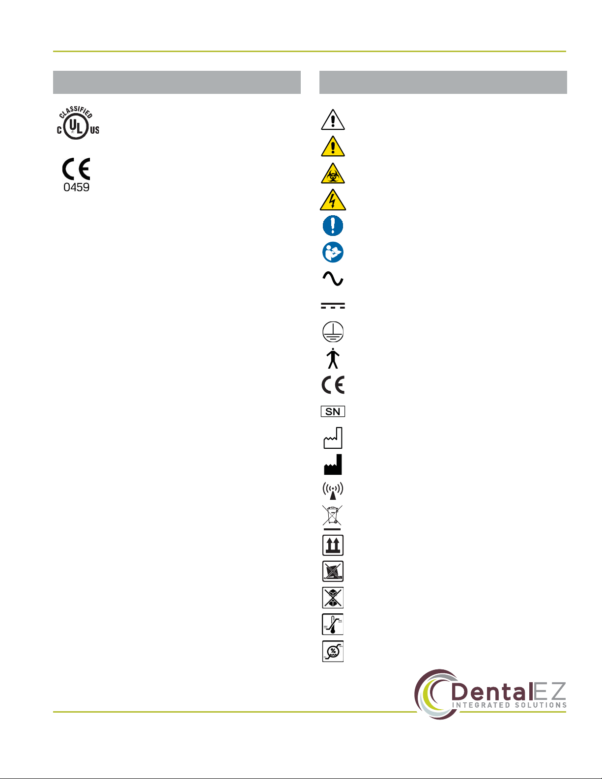
Explanation of Symbols & Signs
Classications
For the purposes of this user manual, the UL
approval is for the unit (head/arm assembly) and
power supply. All other regulatory markings are
provided in their respective manuals.
• Type of Protection Against Electric Shock:
Class 1 Equipment.
• Degree of Protection Against Electric Shock:
Type B Applied Parts. The handpiece is
considered an applied part.
• Degree of Protection Against Ingress of Water:
Ordinary
• Flammable Gases: Equipment not suitable for
use in the presence of a ammable anesthetic
mixture with air, oxygen or nitrous oxide.
• Not intended for use in an oxygen rich
environment.
• Mode of Operation: Continuous
Medical-General Medical Equipment
Certied as to electrical shock, re
and mechanical hazards only in
accordance with:
ANSI/AAMI ES60601-1:2005
CAN/CSA C22.2 NO. 60601-1-08
IEC 80601-2-60:2012
53HN
E355890
The authorized European representative is:
Dental Hygienics & Decontamination (DHD)
41 Blackwell Drive, Braintree Business Park
Braintree Essex, CM7 2PU, UK
Phone: +44 01787 877877 (ext. 200)
= Caution
= Warning
= Biohazard
= Warning - Dangerous Voltage
= General Mandatory Action
= Refer to Manual (Follow Instructions)
= Alternating Current
= Direct Current
= Protective Earth (Ground)
= Type B Applied Part
= European Certication
= Serial Number
= Manufacture Date
= Manufacturer
= Electromagnetic Radiation
= Do Not Trash
= Box Must Remain Upright
= Do Not Place Box on Unlevel Surface
= Do Not Stack Box
= Box Contents Safe Temperature Range
= Box Contents Safe Humidity Range
www.DentalEZ.com 866-DTE-INFO
6
CORETM Console Mounted Unit
PN: 2717-269C
Section I Introduction
Safety Precautions
To satisfy FCC RF exposure requirements
for mobile and base station transmission
devices, a separation distance of 20 cm or
more should be maintained between the
antenna of this device and persons during the
operation. To ensure compliance, operation at
closer that this distance is not recommended.
The antenna(s) used for this transmitter must
not be co-located or operating in conjunction
with any other antenna or transmitter.
CAUTION
• Some illustrations and instructions in
this user manual include installation of
optional city water. If optional city water
is wanted, purchase kit PN 3658-455 for
units with a cuspidor or PN 3658-456 for
units without a cuspidor.
• Isolating the unit from the supply mains is
accomplished by unplugging the unit from
the power receptacle.
NOTICE
Before proceeding with electrical
installation, all wiring must be in
accordance with NEC and local electrical
codes.
To avoid the risk of electrical shock, this
equipment must only be connected to a
supply mains with protective earth.
• Do not modify this equipment without
permission from DentalEZ. Unauthorized
modication will void the warranty and
could result in serious injury. If this
equipment is modied, appropriate
inspection and testing must be conducted
to ensure continued safe use of
equipment.
• Property damage and/or personal injury
may result if directions are not followed or
OEM parts are not used.
• The use of ACCESSORY equipment not
complying with the equivalent safety
requirements of this equipment may lead
to a reduced level of safety of the resulting
system. Consideration relating to the
choice shall include:
• Use of the accessory in the PATIENT
VICINITY
• Evidence that the safety certication
of the ACCESSORY has been
performed in accordance to the
appropriate IEC 60601-1 harmonized
standard.
• Always turn ounit and remove power
from unit when servicing. (Turn opower
at disconnect or service breaker.
• Never leave children unattended when
unit is in use.
WARNING

7
www.DentalEZ.com 866-DTE-INFO
7
DentalEZ®Equipment
PN: 2717-269C
Section I Introduction
Safety Precautions (Continued)
• Medical electrical equipment needs
special precautions regarding
electromagnetic (EMC) compatibility
and needs to be installed according to
EMC information. (See EMC Information
provided in this manual.)
• In accordance with Part 15 of FCC rules,
this equipment was tested and complies
with Class A digital device limits. These
limits are designed to give equipment
reasonable protection against
detrimental interference when operated
in a commercial environment.
• Mobile radio frequency (RF)
communications equipment can aect
medical electrical equipment.
• Accessory equipment not complying with
the Medical Device Safety standard IEC
60601-1 may contribute to a reduced level
of safety of the CORE Delivery Unit. It is
necessary for all accessory equipment
and attachments to comply with IEC
80601-2-60 Medical Electrical Equipment.
NOTICE
This equipment has been tested and found
to comply with the limits for a Class B
digital device, pursuant to Part 15 of the FCC
Rules. These limits are designed to provide
reasonable protection against harmful
interference in a residential installation.
This equipment generates, uses and
can radiate radio frequency energy, and
if not installed and used in accordance
with the instructions, may cause harmful
interference to radio communications;
however, there is no guarantee that
interference will not occur in a particular
installation. If this equipment does cause
harmful interference to radio or television
reception (which can be determined by
turning the equipment oand on) the
user is encouraged to try to correct the
interference by one or more of the following
measures:
• Reorient or relocate the receiving
antenna.
• Increase the separation between the
equipment and receiver.
• Connect the equipment to an outlet on
a circuit dierent from that to which the
receiver is connected.
• Consult the dealer or an experienced
radio/TV technician for help.
NOTICE

www.DentalEZ.com 866-DTE-INFO
8
CORETM Console Mounted Unit
PN: 2717-269C
9
www.DentalEZ.com 866-DTE-INFO
9
DentalEZ®Equipment
PN: 2717-269C
Section II Preinstallation
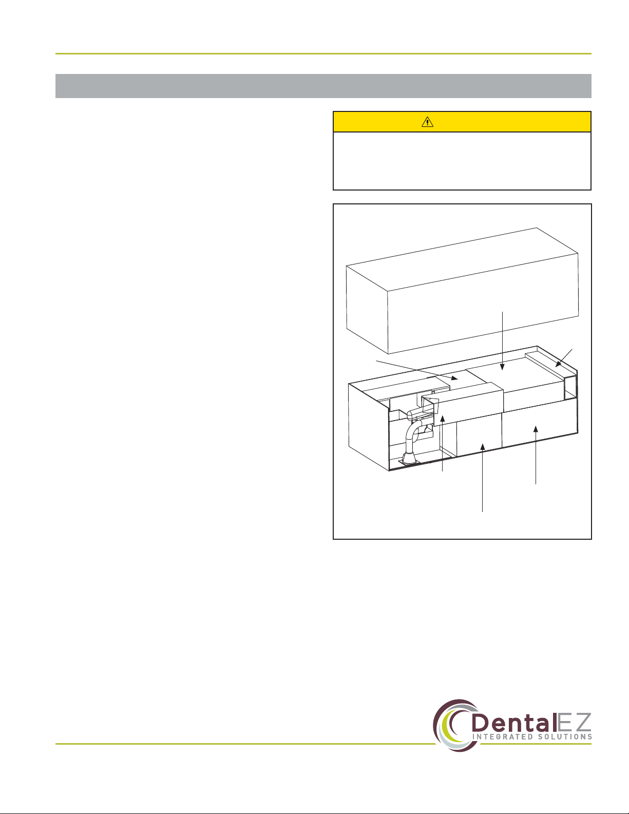
Packaging
Unpacking Unit Cartons
The CORE CMU components are packaged and
shipped according to the carton diagram shown
(Figure 3).
Verify the components packaging contents against
the packing list. All parts supplied are necessary for
proper installation; DO NOT discard any hardware
or components until installation is complete.
NOTE: Cartons may contain empty packing inserts
(even if optional components were ordered).
NOTE: If a pre-tubed chair was ordered, items
marked with an asterisk (*) will be on the chair.
NOTE: If light post was ordered, entire contents
will be inside light post box.
Console Mounted Unit Carton Contents
• Accessory/Options
– Syringe Tubings
– Tray/Tray Pad
• Utility Service Center
• Delivery Head Assembly
• Post-mounted Service Console (with/without
cuspidor)
– Umbilical Assembly
– Foot Control
– Plastic Trim Components
• Optional Components
– Light Post
– High Volume Evacuator (HVE)
– Assistant’s (Instrumentation) Arm
To avoid damage to the carton contents, do
not use a knife or sharp object to open the
packaging.
CAUTION
Delivery
Head Arm
Assembly
Cuspidor
Assembly
Utility
Service
Center
(USC)
Figure 3. CORE CMU carton contents
Console
Assembly
Assistant’s
Instrumentation
Arm (Optional)
Chair
Adaptor
Arm

www.DentalEZ.com 866-DTE-INFO
10
CORETM Console Mounted Unit
PN: 2717-269C
Section II Preinstallation
Unit Placement
• DO NOT position equipment any place
where it would interfere with unplugging
the power cord from the receptacle.
• The plug cannot be located in a position
that requires tools to access.
WARNING
Utility Service Center (USC)
Parts Included
• Utility Service Center (USC)
• USC Cover
• USC Template
• Bag of Supplies
• Set the USC cover aside until all
installation and testing of the delivery
system is complete.
• DO NOT DISCARD the USC template after
use. Neatly refold it and place in it the
back of this user manual.
NOTICE
Tools Required
• Drill
USC Site Preparation
1. Remove and unfold the full-size USC template
found in the USC carton.
2. Position the USC template according to the
exact layout indicated, making certain correct
distance from base to chair is maintained.
3. Using the USC template, drill four corner
mounting holes for the USC base. DO NOT
secure the base to the oor at this time.
NOTE: For wood or metal oors, drill 5/32" holes.
For concrete oors, drill 1/4" holes and install
plastic anchors.
11
www.DentalEZ.com 866-DTE-INFO
11
DentalEZ®Equipment
PN: 2717-269C
Utility Service Center (USC) (Continued)
Plumbing Contractor’s Procedure
Tools Required
• 5/8" Open-end Wrench
USC Installation
NOTE: Items marked with an asterisk (*) are
optional components.
NOTE: If installing the optional cuspidor, optional
city water system components must be installed.
1. Open the USC bag of supplies.
2. Orient the utilities as described in the USC
template and stub through the oor. Vacuum
and drain ttings not supplied; refer to the USC
template for requirements
(Figure 4).
NOTE: Pay close attention to the orientation of the
template to the chair.
3. Sweat the valve adapters to the air and *water
stubs.
4. Apply the appropriate thread sealant to the
valve adapter(s) and install the stop valve(s)
(Figure 5).
• If use of the optional city water system
is planned for in the future, it is highly
recommended to install necessary
components now.
• For reference, a color-coded tubing
diagram is included with this user manual.
NOTICE
Section II Preinstallation
5. Sweat the vacuum elbow to the stub.
6. Sweat the hose connector to the elbow as
applicable and orient as shown in the template.
7. Flush the air and *water lines to remove trash
and debris.
8. Connect the air tting assembly to the air stop
valve as shown in the template. Using a 5/8"
open-end wrench, tighten the nut securely.
9. Connect the *water actuator valve assembly to
the water stop valve as shown in the template.
Using a 5/8" open-end wrench, tighten the nut
securely.
• Before proceeding with plumbing
installation, comply with and maintain all
applicable utility codes and regulations.
WARNING
Figure 4. Utility service center with optional city water
Figure 5. Utility service center with optional city water
Drain
Fitting (Not
Supplied)
Air Stop Valve
Vacuum
Fitting (Not
Supplied)
*Water Actuator
Valve Assembly
Chair Side
(Optional City Water Installation Shown)
Water Stop Valve
(Picture for reference only!)
(Picture for reference only!)
Air Fitting
Assembly

www.DentalEZ.com 866-DTE-INFO
12
CORETM Console Mounted Unit
PN: 2717-269C
Electrical Contractor’s Procedure
The electrical contractor is to provide a covered
115V AC receptacle that meets all applicable utility
codes and regulations (Figure 6).
For the recommended location of the 115V AC
receptacle, refer to the USC template.
NOTE: Electrical contractor’s parts are NOT
supplied.
Rating of main circuit breakers should be
20 Amps maximum.
CAUTION
(Picture for reference only!)
115 V AC
Receptacle
Figure 6. 115V AC receptacle
Section II Preinstallation
13
www.DentalEZ.com 866-DTE-INFO
13
DentalEZ®Equipment
PN: 2717-269C
Console Adaptor Mount
Section III Installation
CORE Chair
Parts Included
• Console Adaptor (Pinch Bolt/Washer Installed)
• Three Leveling Set Screws
• M16 Bolt
Installation
1. Raise the chair base and back to full UP
position.
2. Disconnect the chair from the power supply.
3. Take othe chair seat upholstery by removing
the ve Phillips-head screws from underneath
the chair (Figure 8).
4. Position the support so that the lip of the
chair rests underneath the lip of the washer.
The mount will hold itself in place (Figure 9 -
Figure 10).
Pinch Bolt &
Washer
Figure 7. Console adaptor mount
Leveling Set
Screw Holes (3)
5. Install the M16 bolt loosely into the back of the
mount and into the chair.
6. Rotate console adaptor to the side of the chair
and tighten bolt.
7. Place a level on the support, parallel with and
perpendicular to the chair center line, then
check the level of the support.
NOTE: If leveling is
necessary, adjust the
3/16" set screws until
the unit support is
level
(Figure 11)
.
8. Tighten M16 bolt
(55 foot-pounds).
Figure 8. Remove ve (5) Phillips-head screws
Phillips-head Screws (5)
Figure 9. Position the unit support under the chair
Unit Support
Figure 10. Slide lip of washer onto lip of chair
Figure 11. Adjust set screws
Leveling
Set
Screws
M16 Bolt
www.DentalEZ.com 866-DTE-INFO
14
CORETM Console Mounted Unit
PN: 2717-269C
Section III Installation
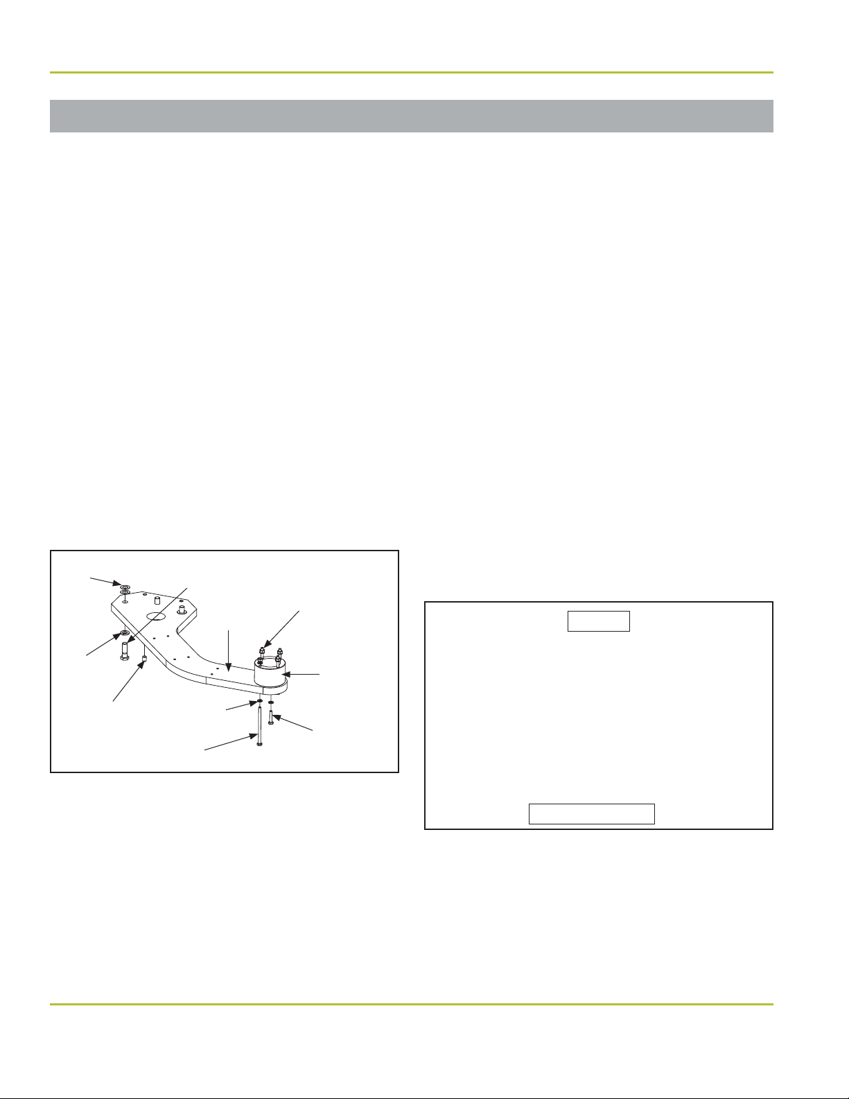
Console Adaptor Mount (Continued)
NuSimplicity Chair
Parts Included
• Console Adaptor
• Spacer
• Two 1/4-20 × 1¼" Hex Head Screws
• Four 1/4-20 × 4" Hex Head Cap Screws
• Ten Zinc Plated, Split Lockwashers
• Four 1/4 × 20 Hex Nuts
• Three 1/2-13 × 1½" Hex Head Screws
• Three 1/2" Split Lockwashers
• Two 3/8-16 × 1/2" Socket Set Screws
• Four 1/2" Flat Washers
Installation
1. Raise the base and back to full UP position.
2. Disconnect the chair from the power supply.
3. Determine if the two outside 1/2" threaded
hole mounting pads and the adaptor bar are
level. If the mounting pads or adaptor bar
are not level, select the necessary amount
of 1/2" at washers needed to provide a level
condition across the two pads.
4. Position the adaptor bar so that the three 1/2"
through holes align with the corresponding
threaded holes of the chair mount casting.
5. Install the two outside 1/2" bolts and lock
washers and the number of 1/2" at washers
determined in step 3 through the adaptor bar
and thread into the chair mount casting.
6. Tighten both outside 1/2" bolts to allow a 3/16"
clearance at the middle 1/2" bolt location.
7. Install the middle 3/8" set screws in the
bottom of the adaptor bar.
8. Install the middle 1/2" lock washer and 1/2"
bolt, but
do not
fully tighten.
9. Place a level on the adaptor bar, parallel with
and perpendicular to the chair center line,
then check the level of the adaptor bar.
NOTE: If leveling is necessary, adjust the 3/8" set
screws until the adaptor bar is level
(Figure 13)
.
10. Tighten all hardware (55 foot-pounds for 1/2"
bolt).
11. Attach the spacer using the 1/4-20 ×1¼" hex
head screws.
Figure 13. Adjust 3/8" set screws if leveling is necessary
1/2" Bolts
Leveling Set Screws
Figure 12. Console adapter parts
1/4-20 ×1¼"
Hex Head Cap Screw
1/4-20
Hex Head Nut
Adaptor Bar
Spacer
Flat
Lockwasher
1/4-20 ×4"
Hex Head Cap Screw
1/2-13 ×1½"
Hex Head Screw
Zinc Plated
Lockwasher
3/8-16 ×1/2"
Socket Set
Screw
1/2" Split
Lockwasher

15
www.DentalEZ.com 866-DTE-INFO
15
DentalEZ®Equipment
PN: 2717-269C
Console
Section III Installation
Tools Required
• Torpedo Level
Installation
1. Place the console on top of the adaptor.
2. Orient the console parallel to the chair with
the water quick-disconnect facing toward the
back of the chair.
3. Locate the four 1/4-20 bolts, washers and nuts
and assemble as shown (Figure 14).
4. Using a torpedo level, check the perpendicular
and parallel levels of the console.
NOTE: If leveling adjustments are necessary,
adjust the set screws on the ange of the console
until the console is level
(Figure 15)
.
Service Console Covers
1. To remove the side covers, simply lift the
covers until the magnets turn loose and take
the side covers oof the console.
NOTE: It is highly recommended to keep the
console side covers ountil all installation and
testing is completed.
2. To replace the side covers, simply align the
magnets and let the covers snap into place.
3. To remove the top cover (the side covers must
be o), remove the two screws holding the
top cover in place (Figure 16).
Figure 14. Locate/assemble 1/4-20 bolts, washers & nuts
1/4-20
Bolts,
Washers &
Nuts (4)
Figure 15. Adjust set screws to level console
Leveling Set Screws
Figure 16. Top cover screws
Screws (2)

www.DentalEZ.com 866-DTE-INFO
16
CORETM Console Mounted Unit
PN: 2717-269C
Assistant’s Arm (Optional)
Basic Fixed Asstistant’s Arm (Cuspidor
Mounted) Carton Contents
• High-volume Evacuator (HVE) Valve Handle
• Saliva Ejector (SE) Valve Handle
• Solids Collector Trap
• Two Inline Connectors (For Syringe Connection)
• 5' Length HVE Tubing
• 5' Length SE Tubing
NOTE: For right-hand operation, mount the
assitant’s arm on the left side (from the
perspective of sitting in the chair).
1. Holders are found attached to the cuspidor.
2. Install the saliva ejector valve, high-volume
evacuator valve and syringe following the
steps outlined in the next section.
Telescoping Assistant’s Arm
1. Place the bushing end of the telescoping arm
onto the pivot pin of the console (Figure 17).
2. If leveling is needed, adjust the set screw on
the underside of the arm section closest to
the end cap (Figure 18).
3. Insert the pivot pin of the tool holder into the
bushing of the telescoping arm. Use the set
screw on the end of the telescoping arm to
adjust the amount of rotational drag desired
(Figure 19).
Figure 17. Place telescoping arm onto pivot pin
Telescoping Arm
Pivot Pin
Figure 18. Adjust set screw if needed
End Cap
Leveling Screw
Figure 19. Use set screw to adjust rotational drag
Set Screw
Tool Holder
Section III Installation
17
www.DentalEZ.com 866-DTE-INFO
17
DentalEZ®Equipment
PN: 2717-269C
Section III Installation
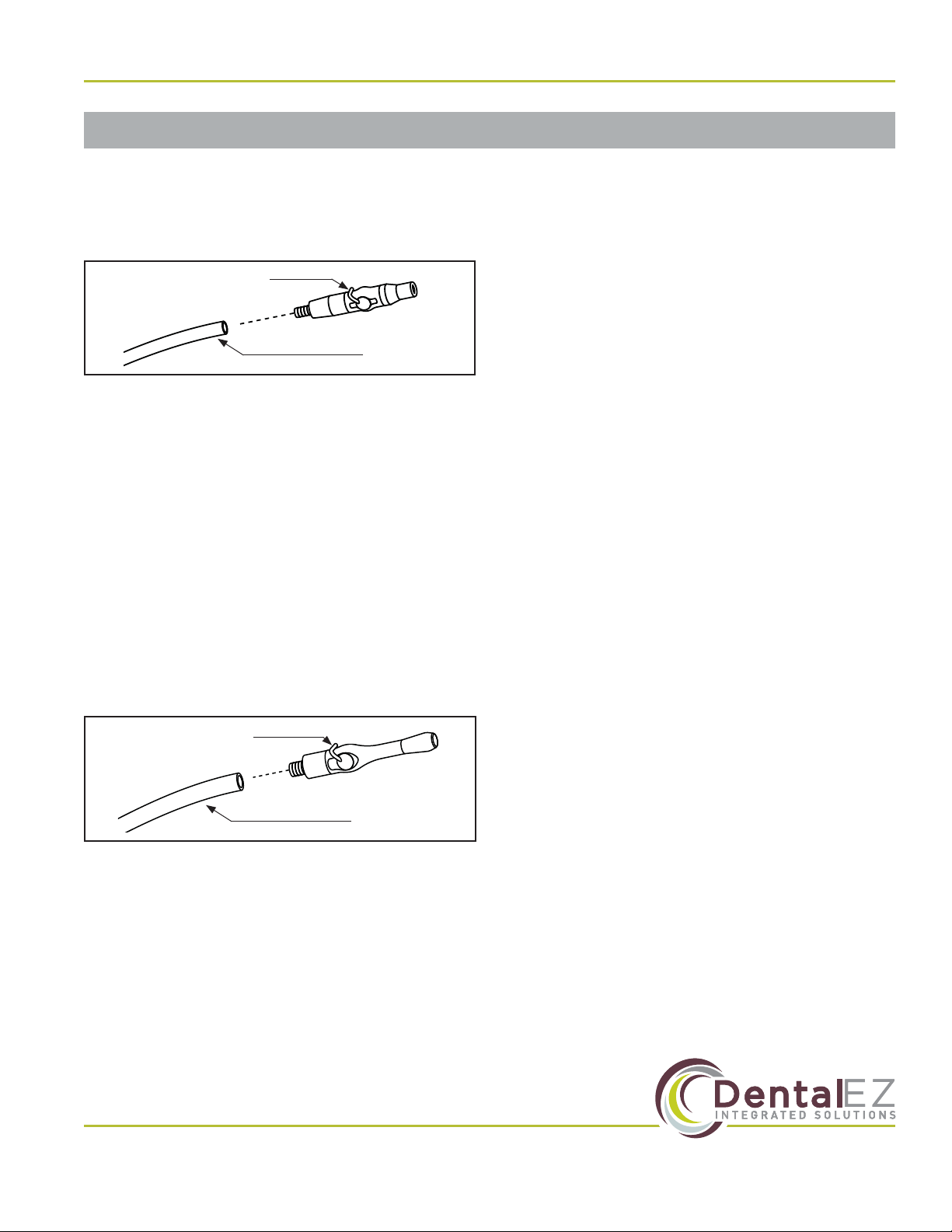
Assistant’s Instrumentation
Saliva Ejector (SE)
1. Connect the SE valve to the 5/16" OD SE
tubing (Figure 20).
2. Hang the SE valve in the instrument holder.
3. Route the SE tubing from the holder through
the access holes on the bottom of the console
chassis (holes found at the edge of the
chassis closest to the head of the chair).
4. Connect the SE tubing to the open 1/4" port
under the solids collector in the service
console.
High-Volume Evacuator (HVE)
1. Connect the HVE valve to the 5/8" OD tubing
(Figure 21).
2. Hang the HVE valve in the instrument holder.
3. Route the HVE tubing from the holder through
the access holes on the bottom of the console
chassis (holes found at the edge of the
chassis closest to the head of the chair).
4. Connect the tubing to an open 1/2" port under
the solids collector in the service console.
Air/Water Syringe
NOTE: The syringe for the delivery head is factory
installed.
1. Pass the syringe tubing from the assistant’s
arm through the bottom opening of the
console and route the tubing up to make
connection in the console. (See the tubing
diagram provided with this manual.)
2. Inside the console, cut othe tubing plug
from the 1/8" red tubing that is marked A
coming from poppet valve (indicated as Point
#1 on the tubing diagram); and cut othe
tubing plug from the 1/8" green tubing that is
marked Wcoming from the 1/4" green water
supply tube (indicated as Point #2 on the
tubing diagram).
IMPORTANT NOTE: Leave the slide clamp on the
A
and
W
tubings at this stage.
3. Connect the Aand Wtubing to the syringe
tubing marked Aand Wfrom the assistant’s
arm by aligning then threading the male and
female quick connects.
4. Connect the syringe to the valve body and
install the nozzle tube assembly.
5. Hang the syringe in the instrument holder.
6. Slide the clamp othe air and water tubes in
the CMU to permit ow.
SE Valve
5/16" OD Tubing
Figure 20. Connect SE valve to OD tubing
HVE Valve
5/8" OD Tubing
Figure 21. Connect HVE valve to OD tubing
Other manuals for Core
2
Table of contents
Other DentalEZ Medical Equipment manuals


Popular Medical Equipment manuals by other brands


PN MEDICAL
PN MEDICAL THE BREATHER CLEANING YOUR DEVICE

Cardiac Science
Cardiac Science Powerheart AED G3 Plus 9390E Operator's and service manual

ProMed
ProMed Lec Control Plus quick guide

RTI
RTI Barracuda Reference manual

burmeier
burmeier DALI II 24 Volt instruction manual

Dräger
Dräger Infinity C700 Quick reference guide


