DentalEZ Core User manual

CORETM Delivery Unit
Magellan Mount
User Manual

i
www.DentalEZ.com 866-DTE-INFO
i
DentalEZ®Equipment
PN: 2717-267C
Table of Contents
Section I Introduction
Product Overview ............................................... 1
Magellan Unit Features ......................................2
Dimensions ........................................................ 3
Specications .................................................... 4
Classications ................................................... 5
Explanation of Symbols & Signs ...................... 5
Safety Precautions............................................ 6
Section II Preinstallation
Packaging .......................................................... 9
Unit Placement ................................................. 10
Utility Service Center (USC).............................10
Section III Installation
Magellan Unit Support ..................................... 13
Umbilical Assembly.......................................... 15
Finalizing USC Installation ............................... 17
Magellan Unit Post............................................ 19
Delivery Head................................................... 20
USC Base........................................................... 21
Rear Assistant .................................................. 21
Assistant’s Arm (Optional).............................. 22
Assistant’s Instrumentation (Optional) ......... 23
Fiber Optic Tubing (Optional).......................... 24
Fiber Optic Electrical (Optional) ..................... 24
Light or Monitor Pole (Optional) ..................... 25
Power Module (Optional)................................. 26
Section IV Testing
Delivery System............................................... 29
Syringe ............................................................. 30
Foot Control and Handpieces......................... 30
Other Optional Features.................................. 32
Section V Operation
Delivery Head................................................... 33
Syringe ............................................................. 34
Foot Control ..................................................... 34
Assistant’s Vacuum Accessories................... 35
Clean Water System........................................ 35
Section VI Care
Cleaning ........................................................... 37
Disinfecting...................................................... 38
Section VII User Service Information
Troubleshooting .............................................. 39
Service Instruction .......................................... 42
Disposal of Equipment.................................... 42
Section VIII Parts Lists/Diagrams
Utility Service Center ...................................... 43
Pivot/Mounting Hardware............................... 43
Simplicity Assistant’s Arm (Optional)............ 44
Galaxy Assistant’s Arm (Optional) ................. 45
CORE Assistant’s Arm (Optional) ................... 46
CORE Delivery Head ........................................ 47
Touch Pads....................................................... 48
Clean Water System........................................ 49
Foot Control ..................................................... 49
Air/Water Syringe ............................................ 50
HVE Nozzle....................................................... 50
Saliva Ejector Nozzle....................................... 50
EMC Information.............................................. 53
Limited Warranty............................................. 55

www.DentalEZ.com 866-DTE-INFO
ii
CORETM Magellan Unit
PN: 2717-267C

1
www.DentalEZ.com 866-DTE-INFO
1
DentalEZ®Equipment
PN: 2717-267C
This manual contains installation, operation and
care instructions, and user service information for
the DentalEZ® CORE™ Magellan Dental Delivery
Unit.
The CORE Magellan unit is intended to be used
by trained professional dental care personnel
only as an interface device to connect the dental
operatory hand instruments to the appropriate
supply utility such as air, water, vacuum, drain and
electrical. It functions as a system management
device that provides a method of operating the
hand instruments from a single control input
device.
The CORE Magellan unit is manufactured to be
used with a dental chair that supports a patient
in a reclined seated position. Operators will be
positioned around the patient’s head as required
for optimum access for the specic procedure
being performed. The delivery unit positions the
handpieces for the optimum presentation to the
operator.
The CORE Magellan unit is designed to provide
trouble-free service when installed, operated and
cared for according to the procedures set forth in
this manual.
To ensure proper installation, carefully
read all of the instructions contained in
this manual, paying close attention to all
warnings, cautions and notes.
Before starting installation procedures, review
the illustration to become familiar with the
components of the CORE Magellan unit (Figure 1).
After the CORE Magellan unit is installed, review
the features, operation procedures, and care
guidelines with the doctor’s sta.
Leave this manual in the doctor’s oice.
Section I Introduction
Product Overview
• Installation by an authorized
DentalEZ dealer service technician is
recommended.
• For any questions about an order, please
contact a DentalEZ Equipment customer
service representative at 866-DTE-INFO.
NOTICE
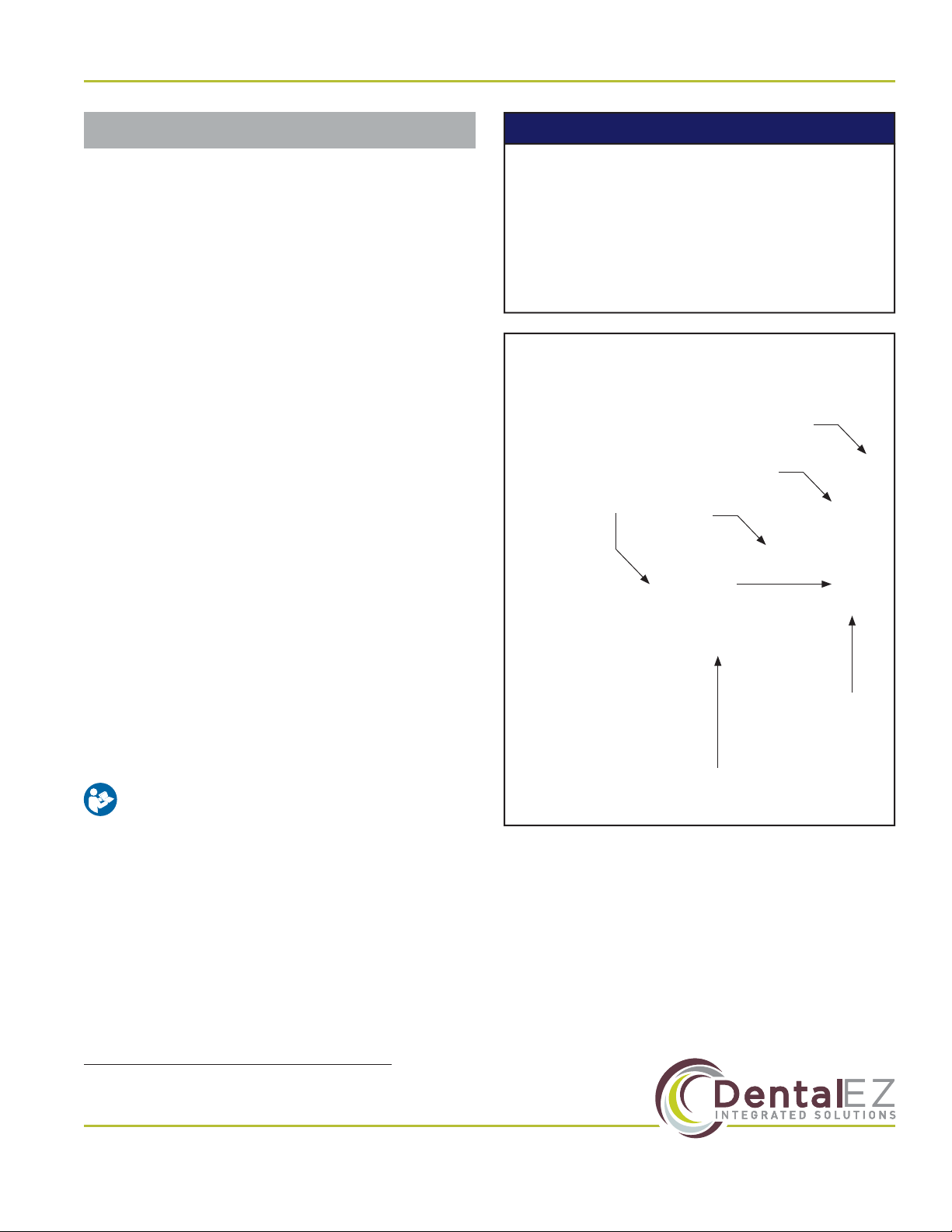
Figure 1. Main components of the CORE Magellan unit
Adjustable
Arm
Light Post
(Optional)
Magellan
Unit Post
Delivery
Head
Clean
Water
System
Magellan
Unit
Support
Rear Assistant’s
Arm & Mount
(Optional

www.DentalEZ.com 866-DTE-INFO
2
CORETM Magellan Unit
PN: 2717-267C
Magellan Unit Features
Designed with simplicity in mind, the CORE product line provides a straightforward, easy-to-use delivery
unit with common components, simple integrated holders and an easy-to-read pressure gauge. The
left/right Magellan-style mount unit positions StarDental® handpieces and ancillaries within easy,
comfortable reach.
Standard Features
• Secure tray placement.
• Air gauge for easy pressure
monitoring.
• Break release handle.
• Easy access control block and
internals for easy maintenance.
• Aluminum ex arm for stability and
ease of positioning.
• Built standard with BioFreeTM tubing.
Optional Features
• Optional integrated dual access touchpad controls.
• Rear assistant’s arm/instrumentation with centrally located solids collector and tubing.
Section I Introduction

3
www.DentalEZ.com 866-DTE-INFO
3
DentalEZ®Equipment
PN: 2717-267C
Section I Introduction
Dimensions
Figure 2. Top and side view dimensions for the CORE Magellan-mount delivery unit
20¾"
1½"
16"
15¼"
24¼"
23½"
21¼"
R26¾"
R23"
10½"
19"
10½-23⅞"
57"
15¾"
41"
6¼"
17½"

www.DentalEZ.com 866-DTE-INFO
4
CORETM Magellan Unit
PN: 2717-267C
Power Supply
• 115V AC, 50/60 Hz, as applicable
Air Pressure
• 551.6 kPa (80 PSI) (at regulator in USC)
Water Pressure
• 275.8 kPa (40 PSI) (at regulator in USC or clean
water manifold)
Clean Water System
• Reservoir capacity: 2.0 L
Shipping (Package) Weight
• CORE Traditional Delivery Head and Arms:
24.5 lb. (11.1 kg)
• Magellan Delivery Unit Post: 13 lb. (5.8 kg)
• Magellan Delivery Unit Support: 20 lb. (9 kg)
• Utility Service Center (USC): 15 lb. (6.8 kg)
• Assistant’s Arm: 16 lb. (7.2 kg)
• Light Post (Optional): 15 lb. (6.8 kg)
Specications
Recommended Environmental Conditions
Transportation and Storage
• Temperature range: -20°F to 165°F
(-29°C to 74°C)
• Relative humidity range: 0% to 95%
Operation
• Temperature range: 59°F to 80°F (15°C to 27°C)
• Relative humidity range: 0% to 95%
• Atmospheric pressure range: 50 to 105 kPa
Section I Introduction

5
www.DentalEZ.com 866-DTE-INFO
5
DentalEZ®Equipment
PN: 2717-267C
Section I Introduction
Explanation of Symbols & Signs
Classications
For the purposes of this user manual, the UL
approval is for the unit (head/arm assembly) and
power supply. All other regulatory markings are
provided in their respective manuals.
• Type of Protection Against Electric Shock:
Class 1 Equipment.
• Degree of Protection Against Electric Shock:
Type B Applied Parts. The handpiece is
considered an applied part.
• Degree of Protection Against Ingress of Water:
Ordinary
• Flammable Gases: Equipment not suitable for
use in the presence of a ammable anesthetic
mixture with air, oxygen or nitrous oxide.
• Not intended for use in an oxygen rich
environment.
• Mode of Operation: Continuous
Medical-General Medical Equipment
Certied as to electrical shock, re
and mechanical hazards only in
accordance with:
ANSI/AAMI ES60601-1:2005
CAN/CSA C22.2 NO. 60601-1-08
IEC 80601-2-60:2012
53HN
E355890
The authorized European representative is:
Dental Hygienics & Decontamination (DHD)
41 Blackwell Drive, Braintree Business Park
Braintree Essex, CM7 2PU, UK
Phone: +44 01787 877877 (ext. 200)
= Caution
= Warning
= Biohazard
= Warning - Dangerous Voltage
= General Mandatory Action
= Refer to Manual (Follow Instructions)
= Alternating Current
= Direct Current
= Protective Earth (Ground)
= Type B Applied Part
= European Certication
= Serial Number
= Manufacture Date
= Manufacturer
= Electromagnetic Radiation
= Do Not Trash
= Box Must Remain Upright
= Do Not Place Box on Unlevel Surface
= Do Not Stack Box
= Box Contents Safe Temperature Range
= Box Contents Safe Humidity Range

www.DentalEZ.com 866-DTE-INFO
6
CORETM Magellan Unit
PN: 2717-267C
Section I Introduction
Safety Precautions
To satisfy FCC RF exposure requirements
for mobile and base station transmission
devices, a separation distance of 20 cm or
more should be maintained between the
antenna of this device and persons during the
operation. To ensure compliance, operation at
closer that this distance is not recommended.
The antenna(s) used for this transmitter must
not be co-located or operating in conjunction
with any other antenna or transmitter.
CAUTION
• Some illustrations and instructions in
this user manual include installation of
optional city water. If optional city water
is wanted, purchase kit PN 3658-484 for
units with a cuspidor or PN 3658-485 for
units without a cuspidor.
• Isolating the unit from the supply mains is
accomplished by unplugging the unit from
the power receptacle.
NOTICE
Before proceeding with electrical
installation, all wiring must be in
accordance with NEC and local electrical
codes.
To avoid the risk of electrical shock, this
equipment must only be connected to a
supply mains with protective earth.
• Do not modify this equipment without
permission from DentalEZ. Unauthorized
modication will void the warranty and
could result in serious injury. If this
equipment is modied, appropriate
inspection and testing must be conducted
to ensure continued safe use of
equipment.
• Property damage and/or personal injury
may result if directions are not followed or
OEM parts are not used.
• The use of ACCESSORY equipment not
complying with the equivalent safety
requirements of this equipment may lead
to a reduced level of safety of the resulting
system. Consideration relating to the
choice shall include:
• Use of the accessory in the PATIENT
VICINITY
• Evidence that the safety certication
of the ACCESSORY has been
performed in accordance to the
appropriate IEC 60601-1 harmonized
standard.
• Always turn ounit and remove power
from unit when servicing. (Turn opower
at disconnect or service breaker.
• Never leave children unattended when
unit is in use.
WARNING

7
www.DentalEZ.com 866-DTE-INFO
7
DentalEZ®Equipment
PN: 2717-267C
Section I Introduction
Safety Precautions (Continued)
• Medical electrical equipment needs
special precautions regarding
electromagnetic (EMC) compatibility
and needs to be installed according to
EMC information. (See EMC Information
provided in this manual.)
• In accordance with Part 15 of FCC rules,
this equipment was tested and complies
with Class A digital device limits. These
limits are designed to give equipment
reasonable protection against
detrimental interference when operated
in a commercial environment.
• Mobile radio frequency (RF)
communications equipment can aect
medical electrical equipment.
• Accessory equipment not complying with
the Medical Device Safety standard IEC
60601-1 may contribute to a reduced level
of safety of the CORE Delivery Unit. It is
necessary for all accessory equipment
and attachments to comply with IEC
80601-2-60 Medical Electrical Equipment.
NOTICE
This equipment has been tested and found
to comply with the limits for a Class B
digital device, pursuant to Part 15 of the FCC
Rules. These limits are designed to provide
reasonable protection against harmful
interference in a residential installation.
This equipment generates, uses and
can radiate radio frequency energy, and
if not installed and used in accordance
with the instructions, may cause harmful
interference to radio communications;
however, there is no guarantee that
interference will not occur in a particular
installation. If this equipment does cause
harmful interference to radio or television
reception (which can be determined by
turning the equipment oand on) the
user is encouraged to try to correct the
interference by one or more of the following
measures:
• Reorient or relocate the receiving
antenna.
• Increase the separation between the
equipment and receiver.
• Connect the equipment to an outlet on
a circuit dierent from that to which the
receiver is connected.
• Consult the dealer or an experienced
radio/TV technician for help.
NOTICE

www.DentalEZ.com 866-DTE-INFO
8
CORETM Magellan Unit
PN: 2717-267C

9
www.DentalEZ.com 866-DTE-INFO
9
DentalEZ®Equipment
PN: 2717-267C
Section II Preinstallation
Packaging
Unpacking Unit Cartons
The CORE Magellan unit components are packaged
and shipped according to the carton diagrams
shown (Figure 3 and Figure 4).
Verify the components packaging contents against
the packing list. All parts supplied are necessary for
proper installation; DO NOT discard any hardware
or components until installation is complete.
NOTE: Cartons may contain empty packing inserts
(even if optional components were ordered).
Magellan Unit Carton Contents
NOTE: If a pre-tubed chair was ordered, items
marked with an asterisk (*) will be on the chair.
• Magellan Unit Support*
• Umbilical*
• Clean Water System
• Tray Package
• Utility Service Center
• Foot Control
To avoid damage to the carton contents, do
not use a knife or sharp object to open the
packaging.
CAUTION
Figure 3. CORE Magellan unit carton contents
Clean
Water
Package
Umbilical*
Magellan
Unit
Support*
Tray
Package
Utility
Service
Center
(USC)
Foot
Control
Unit Post Carton Contents
NOTE: If light post was ordered, entire contents
will be inside light post box.
• Magellan Unit Post
• Installation Hardware
Figure 4. CORE Magellan unit post carton contents
CORE Unit Light
Post (If Ordered)
Magellan
Unit Post Spacer
Installation
Hardware
Installation Hardware
Pole Pivot Supply Bag Magellan Light Supply Bag
(Optional)
Post Pivot Pin Spacer
Two Thrust Bearings #10-32 ×1" Pan-head Screw
Four Thrust Washers Two #10 Internal Tooth Lock
Washers
3/8" x 2¼" Hex-head Bolt Two 5/6" Heavy Duty Electrical
Clamps
.382/.393 ID ×.683 OD Washer #10-32 ×3/8" Pan-head Screw
13/32" ID ×13/16" OD Washer 7-1/2" Nylon Cable Tie
Socket Set Screw Light Adapter Cord Assembly
1/4-20 ×3/8" Set Screw
Rubber Pivot Cover

www.DentalEZ.com 866-DTE-INFO
10
CORETM Magellan Unit
PN: 2717-267C
Section II Preinstallation
Unit Placement
• DO NOT position equipment any place
where it would interfere with unplugging
the power cord from the receptacle.
• The plug cannot be located in a position
that requires tools to access.
WARNING
Utility Service Center (USC)
Parts Included
• Utility Service Center (USC)
• USC Cover
• USC Template
• Bag of Supplies
• Set the USC cover aside until all
installation and testing of the delivery
system is complete.
• DO NOT DISCARD the USC template after
use. Neatly refold it and place in it the
back of this user manual.
NOTICE
Tools Required
• Drill
USC Site Preparation
1. Remove and unfold the full-size USC template
found in the USC carton.
2. Position the USC template according to the
exact layout indicated, making certain correct
distance from base to chair is maintained.
3. Using the USC template, drill four corner
mounting holes for the USC base. DO NOT
secure the base to the oor at this time.
NOTE: For wood or metal oors, drill 5/32" holes.
For concrete oors, drill 1/4" holes and install
plastic anchors.

11
www.DentalEZ.com 866-DTE-INFO
11
DentalEZ®Equipment
PN: 2717-267C
Utility Service Center (USC) (Continued)
Plumbing Contractor’s Procedure
Tools Required
• 5/8" Open-end Wrench
USC Installation
NOTE: Items marked with an asterisk (*) are
optional components.
1. Open the USC bag of supplies.
2. Orient the utilities as described in the USC
template and stub through the oor. Vacuum
and drain ttings not supplied; refer to the USC
template for requirements. (Figure 5)
NOTE: Pay close attention to the orientation of the
template to the chair.
3. Sweat the valve adapters to the air and *water
stubs.
4. Apply the appropriate thread sealant to the
valve adapter(s) and install the stop valve(s).
5. Sweat the vacuum elbow to the stub.
6. Sweat the hose connector to the elbow as
applicable and orient as shown in the template.
• If use of the optional city water system
is planned for in the future, it is highly
recommended to install necessary
components now.
• For reference, a color-coded tubing
diagram is included with this user manual.
NOTICE
Section II Preinstallation
7. Flush the air and *water lines to remove trash
and debris.
8. Connect the air tting assembly to the air stop
valve as shown in the template. Using a 5/8"
open-end wrench, tighten the nut securely.
9. Connect the *water actuator valve assembly to
the water stop valve as shown in the template.
Using a 5/8" open-end wrench, tighten the nut
securely.
Electrical Contractor’s Procedure
The electrical contractor is to provide a covered
115V AC receptacle that meets all applicable utility
codes and regulations. For the recommended
location of the 115V AC receptacle, refer to the
USC template.
NOTE: Electrical contractor’s parts are NOT
supplied.
Rating of main circuit breakers should be
20 Amps maximum.
CAUTION
• Before proceeding with plumbing
installation, comply with and maintain all
applicable utility codes and regulations.
WARNING
Figure 5. Utility service center with optional city water
Drain
Fitting (Not
Supplied)
Air Fitting
Assembly
*Water
Actuator
Valve
Assembly
Vacuum
Fitting (Not
Supplied)
Chair Side
(Optional
City Water
Installation
Shown)

www.DentalEZ.com 866-DTE-INFO
12
CORETM Magellan Unit
PN: 2717-267C

13
www.DentalEZ.com 866-DTE-INFO
13
DentalEZ®Equipment
PN: 2717-267C
Magellan Unit Support
Section III Installation
Parts Included
• Magellan Unit Support
• Three Leveling Set Screws
• M16 Bolt
NOTE: If support is preinstalled, proceed to
Step 6
.
CORE Chair
1. Raise the chair base and back to full UP
position.
2. Disconnect the chair from the power supply.
3. Take othe chair seat upholstery by removing
the ve Phillips-head screws from underneath
the chair (Figure 7).
Pinch Bolt &
Washer
Figure 6. Magellan unit support
Leveling Set
Screw Holes (3)
4. Position the Magellan unit support so that
the lip of the chair rests underneath the lip of
the washer. The mount will hold itself in place
(Figure 8 and Figure 9).
5. Install the M16 bolt loosely into the back of the
mount and into the chair.
6. If support is preinstalled, loosen (but do not
remove) M16 bolt to allow for leveling
(Figure 10).
Figure 7. Remove ve (5) Phillips-head screws
Phillips-head Screws (5)
Figure 8. Position the unit support under the chair
Unit Support
Figure 9. Slide lip of washer onto lip of chair
M16 Bolt
Leveling
Set
Screws
Figure 10. M16 bolt

www.DentalEZ.com 866-DTE-INFO
14
CORETM Magellan Unit
PN: 2717-267C
Section III Installation
Magellan Unit Support (Continued)
NuSimplicity Chair
1. Raise the base and back to full UP position.
2. Disconnect the chair from the power supply.
3. Take othe chair’s seat by removing the
1/4-20 thumb screw from underneath the seat.
Push the seat toward the back of the chair to
clear the substrate from the slide bosses, then
set the seat aside with all related hardware
(Figure 11).
NOTE: If installing the CORE delivery unit on a
DentalEZ chair that is not pre-tubed, continue with
the following instructions. If installing on a pre-
tubed chair,
skip steps 4 through 10
.
Figure 11. Remove the chair seat
Substrate 1/4-20 Thumb
Screw
7. Place a level on the Magellan unit support,
parallel with and perpendicular to the chair
center line, then check the level of the unit
support.
NOTE: If leveling is necessary, adjust the 3/16" set
screws until the unit support is level.
8. Tighten M16 bolt (55 foot-pounds).
NOTE: If necessary, repeat steps 5, 6 and 7 after
unit and light are added to re-level.
4. Select the following items from the Magellan
unit support hardware package:
• Three 1/2" ×1½" Bolts
• Three 1/2" Lock Washers
• Four 1/2" Flat Washers
• Four 1/2" Shims
• Two 3/8" ×1/2" Set Screws
5. Determine if the two outside 1/2" threaded
hole mounting pads and the Magellan unit
support are level. If the mounting pads or unit
support are not level, select the necessary
amount of 1/2" shims needed to provide a level
condition across the two pads.
6. Position the Magellan unit support so that
the three 1/2" through holes align with the
corresponding threaded holes of the chair
mount casting.
7. Install the two outside 1/2" bolts and lock
washers and the number of 1/2" shims
determined in step 5 through the Magellan
unit support and thread into the chair mount
casting.
8. Tighten both outside 1/2" bolts to allow a 3/16"
clearance at the middle 1/2" bolt location.
9. Install the middle 3/8" set screws in the
bottom of the Magellan unit support.
10. Install the middle 1/2" lock washer and 1/2"
bolt, but
do not
fully tighten.

15
www.DentalEZ.com 866-DTE-INFO
15
DentalEZ®Equipment
PN: 2717-267C
11. Place a level on the Magellan unit support,
parallel with and perpendicular to the chair
center line, then check the level of the unit
support.
NOTE: If leveling is necessary, adjust the 3/8" set
screws until the unit support is level
(Figure 12)
.
12. Tighten all hardware (55 foot-pounds for 1/2"
bolt).
Figure 12. Adjust 3/8" set screws if leveling is necessary
1/2" Bolts
Leveling Set Screws
Magellan Unit Support (Continued)
Section III Installation
Umbilical Assembly
CORE Chair
NOTE: Provide suicient slack in the umbilical
assembly to avoid stretching when the chair is in
its full
UP
position.
1. From the umbilical bag of supplies, select
the umbilical assembly with the supplied
L-bracket.
2. Route the umbilical between the hydraulic
pump and the control board, then under the
cantilever arm.
3. Route the remainder of the umbilical through
the pivot and up into the chair casting, using
tie wraps to secure.
NuSimplicity Chair
1. From the umbilical bag of supplies, select
the umbilical assembly with the supplied
L-bracket.
2. Route the umbilical between the hydraulic
pump and the control board, then under the
cantilever arm.
3. Tie wrap the umbilical to the bracket
(Figure 13).
For tubing connections, see the tubing
diagram in the back of this user manual.
NOTICE
Figure 13. Tie wrap umbilical to L-bracket
Tie Wrap
L-bracket

www.DentalEZ.com 866-DTE-INFO
16
CORETM Magellan Unit
PN: 2717-267C
Section III Installation
Umbilical Assembly
4. Route the umbilical through the brackets on
the cantilever and secure using tie wraps
(Figure 14).
5. Route the remainder of the umbilical through
the pivot and up into the chair casting using
tie wraps to secure (Figure 15).
6. Using the two 10-32 screws provided, secure
the L-bracket.
7. Leave the base cover ountil the foot control
has been installed.
Figure 14. Route umbilical through cantilever brackets
Tie
Wraps
Figure 15. Route remainder of umbilical through pivot
Tie Wraps

17
www.DentalEZ.com 866-DTE-INFO
17
DentalEZ®Equipment
PN: 2717-267C
Section III Installation
Finalizing USC Installation
NOTE: The following instructions for nalizing Utility
Service Center (USC) connections include optional city
water installation.
If installing standard clean water
system only, omit steps 10* through 14*
.
NOTE: Refer to the tubing diagram (PN: 2662-304)
in the literature packet for all connections.
1. Select the following hardware items:
• Six 1/8" Tubing Clamps
• Three 1/4" Tubing Clamps
2. Remove the cable wrap to expose the tubing
connections of the umbilical assembly
NOTE: If the pump cover and the chair’s lower
cantilever cover are not already removed, take
them onow.
3. Route the foot control tubing into base of the
chair.
4. Find the foot control leads of the chair’s
umbilical assembly numbered 1, 2, 3and 4
located toward the rear of the chair’s pump
motor assembly.
5. Attach the 1, 2, 3and 4leads with the
corresponding numbered connectors of the
foot control tubing.
6. In the USC, attach the hard, red air line
to the air valve tting using the supplied
compression tting (Figure 16, connection A).
7. Connect the 1/8" red tube from the umbilical
to the poppet valve connection opposite the
existing barb assembled to the 1/4" red tube
(Figure 17, connection C).
8. Connect the 1/8" yellow tube from the
umbilical to the poppet valve connection
opposite the existing barb assembled to the
1/8" yellow tube (Figure 17, connection D).
9. Connect the 1/4" red tube, numbered 1, to the
middle barb of the poppet valve in the USC.
Then secure the connection using a 1/4" tubing
clamp. (This is the drive air line for the foot
control) (Figure 17, connection E).
10. *Attach a 1/4" tubing clamp to the rigid 1/4"
green water line of the water regulator.
11. *Use soap to lubricate the 1/4" barb, then
connect the water line to the water valve
actuator (Figure 16, connection B).
12. *Connect the 1/4" green tube of the umbilical
to the connector from the 1/4" green tube of
the water regulator (Figure 18, connection F).
13. *Attach a 1/8" tubing clamp to the 1/8" yellow
air line of the poppet valve.
14. *Use soap to lubricate the barb of the water
valve actuator. Attach the 1/8" yellow line of
the poppet valve to this barb and secure using
a 1/8" tubing clamp (Figure 18, connection G).
15. If a rear assistant’s arm is installed, slip the
vacuum hose from the chair over the vacuum
elbow in the USC (Figure 18, connection H).
16. If an optional ber optic electrical system
is installed, attach the electrical leads of
the power pack transformer to the adapter
harness. Attach the electrical leads to the
matching connector on the main harness.
17. Route the main harness through the 5' ×1¾"
corrugated ducting hose to the inside of the
chair pump cover (for future connections if
necessary).
18. In the USC, open the air/water stop valves and
check for leaks.
Pictures for the following steps are located on
the next page (Figure 16 - Figure 18).
NOTICE
Other manuals for Core
2
Table of contents
Other DentalEZ Medical Equipment manuals