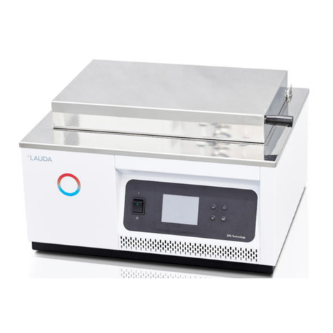
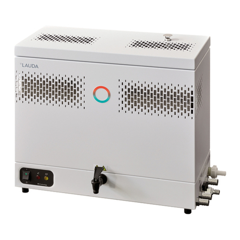
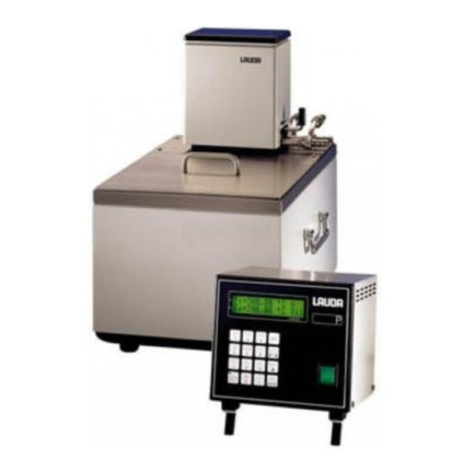
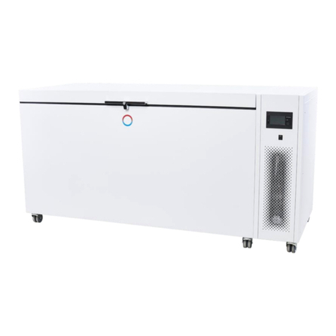
Lauda DLK 10 User manual

2SHUDWLQJLQVWUXFWLRQV
7KURXJKIORZFRROHUV'/.


Read the operating instructions before starting all work.
LAUDA DR. R. WOBSER GMBH & CO. KG
Pfarrstraße 41/43
97922 Lauda-Königshofen
Germany
Valid from series : 04-0001
release English 05/2018 f
replaces release 07/2016 e2; 07/2015 e1; 06/04
YAFE0004 Translation of the original operating instructions
Phone : +49 (0)9343 503-0
Fax : +49 (0)9343 503-222
E-mail [email protected]
Internet http://www.lauda.de
Operating instructions
Through-flow coolers
DLK 10, DLK 25, DLK 45, DLK 45 LiBus


Through flow coolers
16/03/2018 / YAFE0004 Safety notes 3
Safety notes
Before you operate the unit please read carefully all the instructions and safety notes.
If you have any questions please phone us!
Follow the instructions on setting up, operation etc. This is the only way to avoid
incorrect operation of unit and to ensure full warranty protection.
Transport the unit with care!
The unit may NEVER be overturned nor put upside down!
Unit and its internal parts can be damaged :
by dropping
by shock.
Unit must only be operated by technically qualified personnel!
Never operate the equipment without the heat transfer liquid!
Do not start up the unit if
it is damaged
the supply cable is damaged.
Switch off the unit and pull out the mains plug for :
servicing or repair
before moving the unit.
Have the unit serviced or repaired only by properly qualified personnel!
The Operating Instructions include additional safety notes which are identified
by a triangle with an exclamation mark. Carefully read the instructions and
follow them accurately!
Disregarding the instructions may have serious consequences, such as
damage to the unit, damage to property or injury to personnel!
We reserve the right to make technical alterations!

Through flow coolers
4Contents 16/03/2018 / YAFE0004
Contents
SAFETY NOTES....................................................................................................................................................3
CONTENTS..........................................................................................................................................................4
1SAFETY INFORMATION ..............................................................................................................................5
1.1 GENERAL SAFETY NOTES..........................................................................................................................5
1.2 OTHER SAFETY NOTES..............................................................................................................................6
1.3 EU CONFORMITY ......................................................................................................................................6
2BRIEF OPERATING INSTRUCTIONS .........................................................................................................7
3CONTROL AND FUNCTIONAL ELEMENTS...............................................................................................8
4GENERAL CONSTRUCTION AND TECHNICAL DESCRIPTION...............................................................9
5UNPACKING AND SETTING UP................................................................................................................10
5.1 UNPACKING............................................................................................................................................10
5.2 SETTING UP............................................................................................................................................10
6CONNECTION OF EXTERNAL SYSTEMS................................................................................................11
6.1 THERMOSTATS WITHOUT EXTERNAL SYSTEMS..........................................................................................11
6.2 THERMOSTATS CONNECTED TO PRESSURE-TIGHT EXTERNAL SYSTEMS .....................................................12
6.3 THERMOSTATS WITH DUPLEX PUMP OR PRESSURE/SUCTION PUMP CONNECTED TO OPEN BATH ..............13
7ELECTRICAL CONNECTION.....................................................................................................................14
7.1 DLK 10 /25 /45 AND THERMOSTAT WITHOUT MAINS SUPPLY OUTPUT 34H...............................................14
7.2 DLK 10 /25 /45 AND THERMOSTAT WITH MAINS SUPPLY OUTPUT 34 H ....................................................15
7.3 DLK 45 WITH PROPORTIONAL COOLING METHOD......................................................................................16
7.4 DLK 10 /25 AND PROLINE HEATING THERMOSTATS WITH PROPORTIONAL COOLING METHOD......................17
7.5 DLK 45 LIBUS AND PROLINE HEATING THERMOSTATS WITH PROPORTIONAL COOLING METHOD..................18
8STARTING UP ............................................................................................................................................19
9MAINTENANCE ..........................................................................................................................................20
9.1 CLEANING ..............................................................................................................................................20
9.2 REPAIR AND DISPOSAL NOTE...................................................................................................................21
9.3 HELP DESK AND ORDERING REPLACEMENT PARTS....................................................................................21
10 TECHNICAL DATA.....................................................................................................................................22
10.1 REFRIGERANT AND FILLING QUANTITY......................................................................................................23
10.2 FUSES ...................................................................................................................................................23
Special Symbols:
Danger:
This symbol is used where there may be injury to
personnel through incorrect handling.
Note:
Here special attention is drawn to some aspect. May
include reference to danger.
Reference
Refers to additional information in other sections.

Through flow coolers
16/03/2018/ YAFE0004 Safety information 5
1 Safety information
1.1 General safety notes
A through flow cooler serves for due cooling of heat transfer liquids which are tempered by means of
a bath thermostat and transferred by pumping. This leads to hazards through high temperatures, fire,
and the general hazards through the use of electrical energy.
The user is largely protected through the application of the appropriate standard specifications.
Additional hazards may arise from the type of material being thermostated, e.g. when going above or
below certain temperature levels or through breaking of the container and reaction with the heat
transfer liquid.
It is not possible to cover all possibilities; they remain largely within the responsibility and the
judgement of the user.
The equipment must only be used as intended and as described in these Operating
Instructions. This includes operation by suitably instructed qualified personnel.
The units are not designed for use under medical conditions according to DIN EN 60601-1 or
IEC 601-1!
Classification in accordance with EMC requirements
Device
Immunity
Emissions class
Customer power
supply
Through-flow cooler
DLK 10
DLK 25
Type 2 in accordance
with
DIN EN 61326-1
Emissions Class B
in accordance with
CISPR 11
Worldwide
No limitation
Through-flow cooler
DLK 45
DLK 45 LiBus
Type 2 in accordance
with
DIN EN 61326-1
Emissions Class B
in accordance with
CISPR 11
Only for EU
Domestic connection
value ≥ 100 A
Through-flow cooler
DLK 45
DLK 45 LiBus
Type 2 in accordance
with
DIN EN 61326-1
Emissions Class B
in accordance with
CISPR 11
Rest of the world
(outside EU)
No limitation

Through flow coolers
6Safety information 16/03/2018 / YAFE0004
1.2 Other safety notes
Connect the equipment only to an earthed supply socket.
Use suitable hoses.
Protect tubing with hose clips against slipping off. Prevent kinking of tubing!
Check tubing from time to time for possible material fatigue!
Heat transfer tubing and other hot parts must not come into contact with the supply cable!!
During operation of the through flow cooler, hot tempering liquid may penetrate through the hose in
case of hose rupture, thus constituting a danger to persons and material goods.
vapours to be produced. Ensure appropriate ventilation!
When changing the heat transfer liquid from water to liquids for temperatures above 100 °C
carefully remove all traces of water, also from tubing and from the external circuit, otherwise
danger of burns through delayed boiling!
Always pull out the mains plug before cleaning, maintenance or moving the through-flow cooler!
Repairs must only be carried out by properly qualified personnel!
Values for temperature control and indicating accuracy apply under normal conditions according to
DIN 12876. High-frequency electromagnetic fields may under special conditions lead to
unfavourable values. This does not affect safety!
1.3 EU conformity
The device complies with the basic health and safety requirements outline in the
Directives listed below.
Machinery Directive 2006/42/EC
EMC Directive 2014/30/EU
LAUDA DR. R. WOBSER GMBH & CO. KG –Pfarrstraße 41/43 -
97922 Lauda-Königshofen - Germany
The device does not fall under Pressure Equipment Directive
2014/68/EU because the device is only classified as high as
Category 1 and is covered by the Machinery Directive.
Depending on the heat transfer liquid used and the method of operation it is possible for irritating

Through flow coolers
16/03/2018 / YAFE0004 Brief operating instructions 7
2 Brief operating instructions
Check through-flow cooler during unpacking for any transport damage, and if necessary, inform the
carrier or the post office.
The unit may NEVER be overturned nor put upside down!
- Set up unit according to chapter 5.
- Connect tubing according to chapter 6.
Thermostats without external systems (Chapter 6.1).
Thermostats connected to pressure-tight external systems (Chapter 6.2).
Thermostats with DUPLEX pump or pressure/suction pump connected to
open bath
(Chapter 6.3).
- Secure tubing with clips to prevent slipping-off.
- Check the supply voltage against the data on the rating label. Insert the mains plug.
Switching on: First switch on thermostat, and then switch on through-flow cooler at
main power switch (green signal lamp lights up).
Switching off: First switch off through-flow cooler, and then switch off thermostat.
Never allow the through-flow cooler to run without liquid flowing through.

Through flow coolers
8Control and functional elements 16/03/2018 / YAFE0004
3 Control and functional elements
DLK 10 Mains switch
DLK 25 Pilot lamp Mains switch
DLK 45 Pilot lamp Mains switch
Switches located on the through flow coolers DLK 25 and DLK 45
Pilot lamp cooling unit
Cooling unit to be switched on manually.
AUTO Cooling unit automatically controlled with
thermostat.
Mains switch ON
DLK 45 LiBus Mains switch

Through flow coolers
16/03/2018 / YAFE0004 General construction and technical description 9
4 General construction and technical description
These operating instructions apply to four through-flow coolers of various cooling capacities.
Common feature of all four units are the air-cooled, fully hermetically sealed and thus maintenance-
free refrigeration units, the heat carrier circuit in stainless steel and the possibility of electrical
connection to LAUDA thermostats.
The refrigeration unit consists essentially of a hermetically sealed compressor. Heat of condensation
and motor heat are dissipated through a fan-cooled finned tube condenser. The fresh air is drawn in at
the front of the unit; the heated is discharged to the back and to the side. In order to ensure problem-
free air circulation the ventilation openings must not be obstructed.
The compressors have an over-temperature cut-out which acts on the compressor temperature and
current consumption of compressor. Furthermore the cooling system is protected by an overpressure
cut-out against excessive pressure.
The built-in refrigeration unit continuously cools down a heat exchanger (evaporator) insulated with
polyurethane foam. The connections of the heat exchanger are mounted at the back and are provided
with tube fittings M16 x 1 to connect olives with a diameter of 13 mm / 11 mm or metal hoses. The
pump of the connected thermostat pumps the heat transfer liquid through the heat exchanger of the
through-flow cooler. The through-flow cooler continuously cools down and the thermostat maintains
the required temperature by means of controlled counter-heating.
The through flow cooler DLK 45 equipped with LAUDA heating thermostats of the Ecoline E 3XX
series and older thermostats with incorporated P electronics allow a method of operation
corresponding to the proportional cooling. The cooler DLK 45 LiBus with LAUDA heating thermostats
with LiBus (at present Proline) also allows a method of operation which is equivalent to the
proportional cooling.
The cooling capacities indicated in the technical data sheet are gross values. To get the true effective
cooling capacities in case of operation, the heat emission of the pump as well as the insulation losses
have to be taken into consideration and deducted. This is decisive for the lowest temperature which
can be reached if a thermostat is connected. The indicated operating temperature range refers to the
combination with a small or medium-sized bath/circulation thermostat.
(i. e. DLK 10 –E 103; DLK 25 –P 8 C; DLK 45 –PVL 24.)

Through flow coolers
10 Unpacking and setting up 16/03/2018 / YAFE0004
5 Unpacking and setting up
Never put the device into operation if you have discovered any transport damage.
The unit may NEVER be overturned nor put upside down!
5.1 Unpacking
Carefully packing should prevent transport damage. If, however, the units should arrive damaged, the
carrier or the post office has to be informed so that it can be inspected.
Standard accessories
Cat. No.
2 Screw caps
HKM 032
2 Olives Ø13 mm
HKO 026
1 DLK Mains cable
DLK 10, DLK 25
UK 226
1 valve control line
DLK 45 for Ecoline E 3XX and P control unit thermostat
UK 251
1 power control line
DLK 45 for Ecoline E 3XX and P control unit thermostat
UK 227
1 Operating Instructions
for all DLK
YAFE0004
Optional accessories
Cat. No.
1 power control line
DLK 10, DLK 25 for Ecoline E 3XX thermostat and
P control unit thermostat
UK 227
1 Proline control line
DLK 10, DLK 25
UK 263
1 LiBus extension, 5 m
DLK 45 LiBus
EKS 068
1 LiBus T-distributor
DLK 45 LiBus
EKS 073
5.2 Setting up
The condenser of the refrigeration unit is air-cooled. Fresh air is drawn in at the front of the unit and
blown out at the back. Thus, the unit must be set up so that the free air flow is not obstructed.
Recommended distance: 50 centimetre at least.
It is particularly important that the air drawn in is not excessively warm. The unit must not be placed near
a radiator or any other source of heat.
Higher ambient temperatures result in a reduced performance. When the compressor is overloaded
because of high refrigerant pressure or high ambient temperature, the power supply is automatically
interrupted via a temperature switch. The compressor switches on automatically as soon as it has
cooled down.
air outlet
air inlet

Through flow coolers
16/03/2018 / YAFE0004 Connection of external systems 11
6 Connection of external systems
A through-flow cooler can be only connected to thermostats which are equipped with a circulating
pump and connectors for the connection of external circulating systems. For connection the use of
insulated tubing with a maximum possible inside diameter is recommended.
To guarantee good circulation of the pump the tubing should not be too long. If possible, place the
through-flow cooler directly near the thermostat, especially when operating with the DLK 45 and the
DLK 45 LiBus with proportional cooling.
Secure tubing with clips to prevent its slipping off or use stainless steel metal hoses with screwed
connections!
6.1 Thermostats without external systems
Thermostat
DLK
The figure shows the easiest possibility of connection. The connectors of the circulating pump are
connected to the fittings of the through-flow cooler.
Pay attention to the through-flow direction! If the connections are interchanged, the
cooling capacity will be reduced as an air cushion may develop in the plate-heat
exchanger.

Through flow coolers
12 Connection of external systems 16/03/2018 / YAFE0004
6.2 Thermostats connected to pressure-tight external systems
Thermostat
DLK
If a pressure-tight external system is connected to the thermostat, the through-flow cooler must be
incorporated in the return line (suction line) of external system and thermostat.
pressure-tight consuming device

Through flow coolers
16/03/2018 / YAFE0004 Connection of external systems 13
6.3 Thermostats with DUPLEX pump or pressure/suction pump connected to
open bath
Thermostat
DLK
If the thermostat is equipped with a DUPLEX pump or a pressure/suction pump and an open bath is
thermostated, it is also possible to connect the through-flow cooler. The through-flow cooler must be
incorporated in the return line (suction line).
- Only possible with devices provided with suction press pump.
- Use constant level device on the open bath.
- Not possible with LAUDA Ecoline.
constant level device
open bath

Through flow coolers
14 Electrical connection 16/03/2018 / YAFE0004
7 Electrical connection
7.1 DLK 10 / 25 / 45 and Thermostat without mains supply output 34H
First switch on thermostat, then switch on through-flow cooler by means of the mains switch (green
signal lamp lights up).
Switches located on the DLK
DLK 10
Mains ON
37 H
DLK- Mains
cable UK 226
Only switch on the
mains switch if
thermostat is in
operation.
DLK 25
38 H (not used)
37 H
DLK- Mains
cable UK 226
Adjust (manual).
Only switch on the
mains switch if
thermostat is in
operation.
Unit cools if the mains switch is switched ON.
DLK 45
39 H (not used)
38 H (not used)
DLK- Mains
cable
Adjust (manual).
Only switch on the
mains switch if
thermostat is in
operation.
Unit cools if the mains switch is switched ON.

Through flow coolers
16/03/2018 / YAFE0004 Electrical connection 15
7.2 DLK 10 / 25 / 45 and Thermostat with mains supply output 34 H
The DLK is switched on and off by the thermostat.
This output is provided on Ecoline E 3XX and older LAUDA thermostats with P electronics!
The system operates with continuous cooling and controlled heating.
The DLK only cools in case that the thermostat is switched ON.
Switches located on the DLK
DLK 10
Mains ON
DLK 25
Mains cable
Mains ON
Adjust AUTO
DLK 45
not used Mains cable
Mains ON
Adjust AUTO
When using thermostats with P electronics select “DLK standard”in the menue “Parameters”!

Through flow coolers
16 Electrical connection 16/03/2018 / YAFE0004
7.3 DLK 45 with proportional cooling method
The DLK is switched on and off by the thermostat.
It is possible in combination with Ecoline E 3XX and older LAUDA thermostats with P electronics!
DLK 45
This method of operation offers the same functions as the proportional cooling at LAUDA refrigerated
thermostat. This method does not use counterheating.
Caution: Thermostat with software version 2.14 minimum or higher.
In the menu “parameters”of the thermostat either DLK standard operation (= with controlled heating)
or DLK automatic operation (=proportional cooling) can be chosen.
For automatic operation with proportional cooling choose „DLK automatic“. Put the yellow switch at
the DLK 45 to AUTO.
Pilot lamp Cooling unit
Mains switch ON
Adjust AUTO
Mains cable

Through flow coolers
16/03/2018 / YAFE0004 Electrical connection 17
7.4 DLK 10 / 25 and Proline heating thermostats with proportional cooling method
The DLK is switched on and off by the thermostat.
Operation of the DLK control unit is only possible with Proline heating thermostats (no cooling
thermostats!).
The "No." specified on the rating plate located on the back of the master unit, must be ≥ 04-0001.
The use of a through flow cooler has to be defined in the thermostat.
The system operates with continuous cooling and controlled heating.
The DLK only cools in case that the thermostat is switched ON.
Master:
MNEnu PArA tFC =1
Command:
Menu Settings Basic Settings DLK connected = Yes
Switches located on the DLK
DLK 10
Mains ON
DLK 25
Mains ON
Adjust AUTO

Through flow coolers
18 Electrical connection 16/03/2018 / YAFE0004
7.5 DLK 45 LiBus and Proline heating thermostats with proportional cooling
method
The DLK 45 LiBus is switched on and off by the Proline heating thermostat.
Operation of the DLK control unit is only possible with Proline heating thermostats (no cooling
thermostats!).
The “No.”specified on the rating plate located on the back of the master unit, must be ≥ 04-0001.
The use of a through flow cooler has to be defined in the thermostat.
The system operates with proportional cooling and automatic compressor.
The DLK only cools in case that the thermostat is switched ON.
Switches located on the DLK
DLK 45 LiBus
LiBus-cable
Mains ON
This method of operation has the same functions as the proportional cooling of LAUDA cooling
thermostats.
Proline thermostat with software version:
for control system V1.33
for operating system (command) V1.36
or higher required.
The thermostat allows switching between the following DLK modes:
"0" (always OFF),
"1" (always ON) and
"A" (automatic mode).
Master:
MNEnu MNodu Cool Co 0
1
A
Command:
Menu Interfaces SmartCool Cooling mode off
on
automatic
DLK mains
cable
This manual suits for next models
3
Table of contents
Other Lauda Laboratory Equipment manuals
Popular Laboratory Equipment manuals by other brands

Olympus
Olympus SZX-RFL2 instructions

Agilent Technologies
Agilent Technologies 4100 Site preparation guide

Northern Digital
Northern Digital Optotrak Certus user guide

Caframo
Caframo BDC2002 instruction manual

BioLAB
BioLAB BIFL-207 Operation manual

Cascade Sciences
Cascade Sciences CVO-5-EX Series Installation & operation manual

Four E's Scientific
Four E's Scientific WB301 operating instructions

UVD ROBOTS
UVD ROBOTS B user manual

Prior Scientific
Prior Scientific OptiScan II ES111 operating instructions

Hygiena
Hygiena Dualo 32 R2 Product instructions

Memmert
Memmert UNB 100 operating instructions

cetoni
cetoni ROTAXYS 360 Hardware manual