• Use indoors only.
• Never operate the unit in close proximity to combustible materials or place materials on top of the unit.
• The unit must be electrically grounded to a three-wire electrical outlet or receptacle. The electrical service
provided must be a dedicated line of the proper size according to local electrical codes.
• Unit must be placed in a position that allows the power cord to be easily disconnected from the wall.
• Do not attempt to service the unit until you have read and understand this instruction manual.
• Turn off the power switch and disconnect the power cord before attempting to service the unit.
• Do not operate the unit controls with tongs or other tools.
• Do not use solvents or liquid cleaners on the control panel.
• Do not touch the bulbs when the unit door is open.
• Before replacing bulbs, allow the unit to cool to room temperature to avoid burns.
• Do not cover the top of the unit or obstruct the rear fans in anyway.
• Do not heat water or food in the unit chamber.
• Do not submerge the unit into any liquid.
• Do not store flammable products or solvents inside the unit chamber.
• Follow the manufacturer’s instructions for use for maximum appliance load per process and cure cycle.
• If the unit is not operated in the manner as specified in this manual, the protection provided by the unit
may be impaired.
• Pollution Degree: 2
CAUTION: RISK OF DANGER! BURN HAZARD IS PRESENT WHEN COVER IS OPENED.
USE CAUTION AFTER OPENING COVER, BULBS AND METAL SURFACES MAY BE HOT!
USE HEAT-RESISTANT GLOVES WHEN REMOVING BULBS!
SYMBOL TABLE
Alternating current
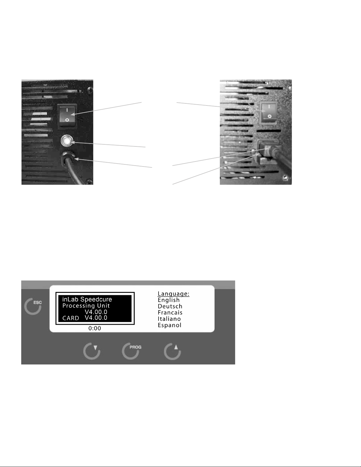
IOn (Power Switch)
OOff (Power Switch)
Caution, Hot Surface
Protective Conductor
!Caution, Risk of Danger
High Intensity Light
Dispose of in accordance with the Waste Electrical and Electronic Equipment Directive
2012/19/EU of the European Parliament and the Council of the European Union
SAFETY
1
!
FOR PROFESSIONAL USE ONLY.
Please read these operating instructions carefully before installing or operating this equipment.