PSI LaiPen LP 110 Manual

Page | 2
Manual Version: 2023/11
© PSI (Photon Systems Instruments), spol. s r.o.
www.psi.cz
This document and its parts can be copied or provided to a third party only with the express permission of PSI.
The contents of this manual have been verified to correspond to the specifications of the device. However, deviations cannot be ruled out.
Therefore, a complete correspondence between the manual and the real device cannot be guaranteed. The information in this manual is
regularly checked, and corrections may be made in subsequent versions.
The visualizations shown in this manual are only illustrative.
This manual is an integral part of the purchase and delivery of equipment and its accessories and both Parties must abide by it.

Page | 3
TABLE OF CONTENT
1Information Before Using the Device..................................................................................................... 5
2Device Description and Accessories....................................................................................................... 6
2.1 Accessories ...................................................................................................................................................7
2.1.1 Notebook Computer.....................................................................................................................................7
2.1.2 Telescopic Rod ..............................................................................................................................................7
2.1.3 Tripod............................................................................................................................................................7
2.1.4 Substitute Connection Cable ........................................................................................................................7
3Technical Specifications......................................................................................................................... 8
4Principle of Measurement ..................................................................................................................... 9
4.1 Measured Parameters ..................................................................................................................................9
4.2 Measuring Reference Values ......................................................................................................................10
4.2.1 Distance Nearest Shading Obstacle ............................................................................................................10
4.2.2 Measurement Relative to the Sun..............................................................................................................10
4.2.3 Reference for Single Sensor Mode of Measurement .................................................................................11
4.2.4 Reference for Dual Sensor Mode of Measurement....................................................................................12
5Getting Started.................................................................................................................................... 13
5.1 General Guide to Measurement.................................................................................................................13
5.2 Dark Calibration Prior to Measurement .....................................................................................................13
5.3 Single Sensor Mode of Measurement ........................................................................................................14
5.4 Dual Sensor mode of Measurement...........................................................................................................15
5.5 Multiple Angle mode of Measurement ......................................................................................................16
5.6 Example of Zenith Angle Measurement and Lai Calculation ......................................................................17
6Control Menu Tree .............................................................................................................................. 19
7Connecting via USB cable .................................................................................................................... 24
8Connecting via Bluetooth .................................................................................................................... 24
9FluorPen Software............................................................................................................................... 25

Page | 4
9.1 Software Installation...................................................................................................................................25
9.2 Menu and Icons Explanation ......................................................................................................................26
9.2.1 Main Menu .................................................................................................................................................26
9.2.2 Menu Settings.............................................................................................................................................27
9.3 Data Download and Visualization...............................................................................................................27
9.3.1 Single Sensor Mode ....................................................................................................................................27
9.4 Data Export .................................................................................................................................................28
10 Firmware Update ................................................................................................................................ 29
11 GPS Module......................................................................................................................................... 31
11.1 GPS operation .............................................................................................................................................31
11.2 Data download............................................................................................................................................32
12 Warranty terms and conditions........................................................................................................... 33
13 References .......................................................................................................................................... 33
14 List of Figures ...................................................................................................................................... 34

Page | 5
1INFORMATION BEFORE USING THE DEVICE
Carefully unpack the carton. You should have received the following items:
•LaiPen LP 110
•Carrying case
•Textile strap for comfortable wearing
•Installation USB flash drive with FluorPen software, USB driver and this guide
•Connection cable (4 Pin Male to USB 2.0 A Male)
•Other accessories or features based on specific order
If any item from the list above is missing, please, contact PSI. Also check the package for any visible external damage. If you find any
damage, notify the carrier and PSI immediately. The carton and all packing materials should be retained for inspection by the carrier or
insurer.
Before starting operation of the instrument read this manual carefully and follow the instructions. If you are not sure about anything in
the manual, contact the manufacturer for prominence. By taking this device, the customer agrees to follow the instructions in this guide.
Always follow the specific instructions for use and maintenance of equipment and its accessories. It is forbidden to interfere to the
hardware and software part of the device and its accessories.
Copying or other interference in software is considered copyright infringement and is sanctioned in accordance with the relevant
legislation. These activities can also lead to loss of warranty on the device and its accessories. Those activities may also cause damage to
health and property.
Read this manual carefully before operating the device. If you are not sure about something in the manual, contact the manufacturer
for clarification.
By accepting the device, the customer agrees to follow the instructions in this guide.
Always follow corresponding manuals while working with the device or doing the maintenance. It is forbidden to interfere with the
hardware or software of the device in any way without previous agreement with the manufacturer.
The following table presents basic highlight symbols used in this manual:
Symbol
Description
Important information, read carefully.
Complementary and additional information.
Page | 6
2DEVICE DESCRIPTION AND ACCESSORIES
Instrument for fast and easily repeatable measurements of Leaf Area Index (LAI) from solar radiation. The LaiPen was designed by
scientists and engineers to provide instant readouts that can be exported to computer for further processing. Unlike in other similar
instruments measuring LAI, the LaiPen LP 100 is accurate in most daylight conditions and does not require cloud cover or specific sun
angles for its proper performance. ALAI irradiance is an irradiance of the blue part of visible spectrum and can be measured with a LAI
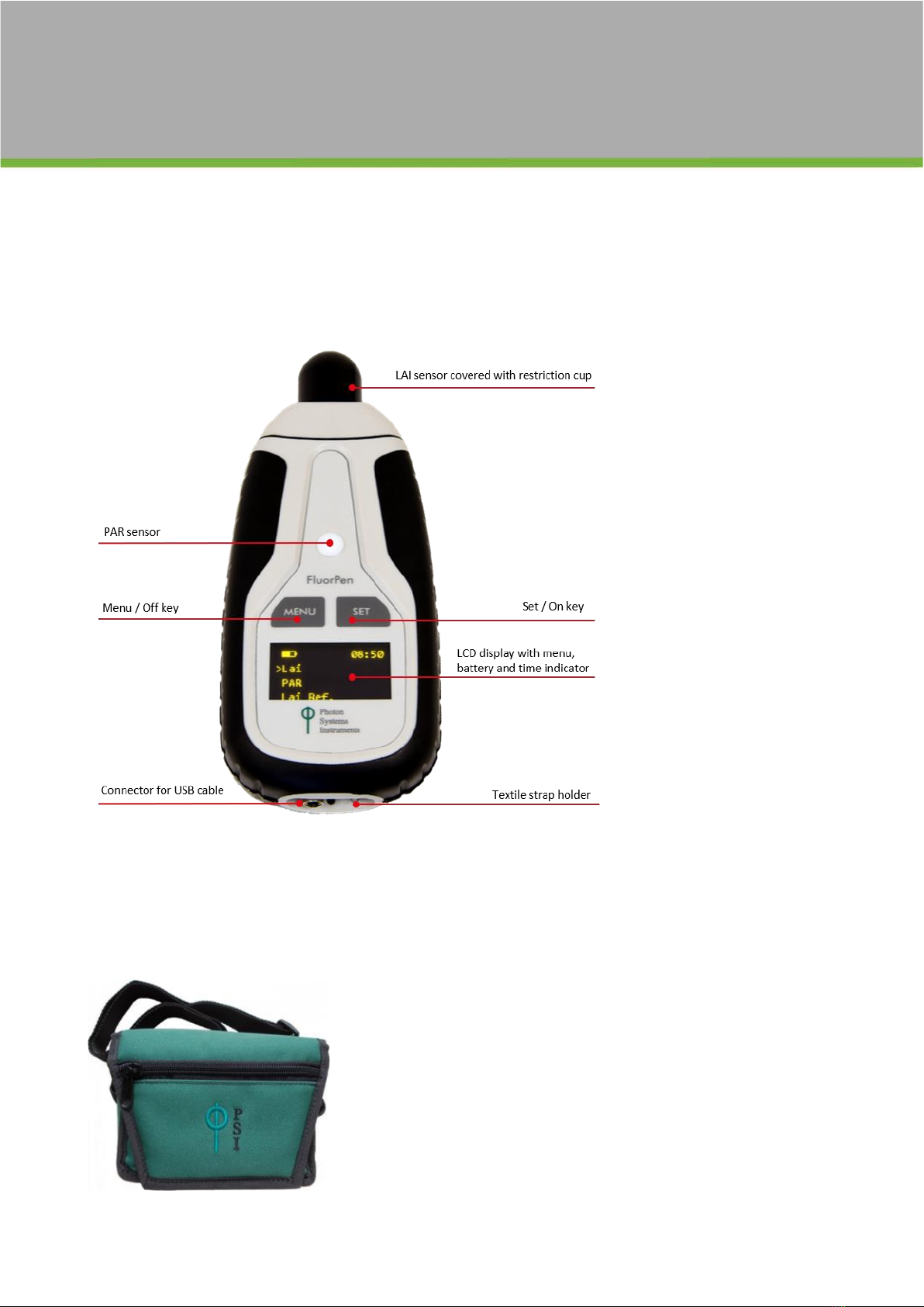
sensor, which is placed on a side of the LaiPen instrument. The LAI sensor is covered with a black restriction cup (Fig. 1). PAR can be
measured with a PAR sensor, which is placed in the middle of the front side of the instrument (Fig. 1).
Fig. 1 LaiPen LP 110 Physical Features
LaiPen device is supplied with the following items:
•Connection cable
•Padded carrying case to protect the instrument during transportation (Fig. 2)
•Control software and manual on a USB stick
•Textile strap
Fig. 2 Padded carrying case to protect the instrument during transportation
Page | 7
2.1 ACCESSORIES
2.1.1 NOTEBOOK COMPUTER
Portable notebook computer (laptop). The type and specification vary according to current availability on the market. For detailed
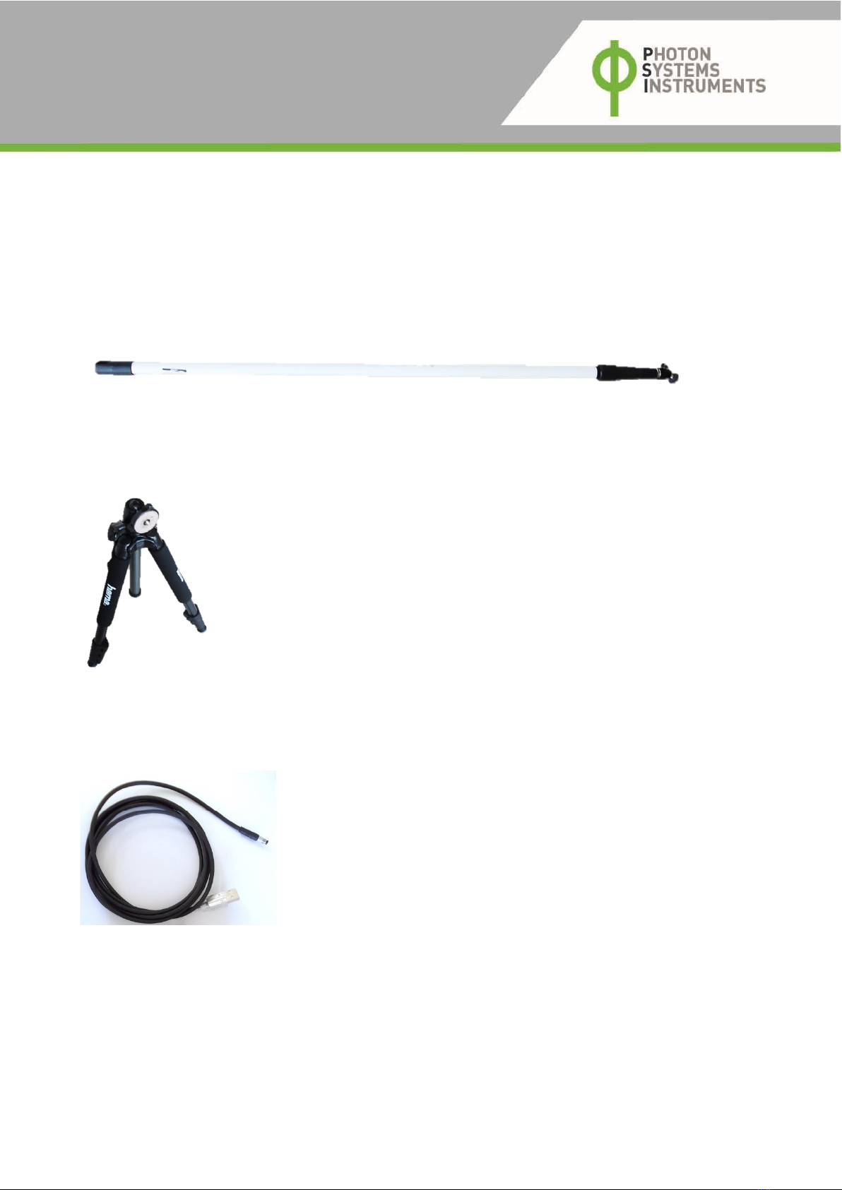
2.1.2 TELESCOPIC ROD
LaiPen instrument attached to a telescopic rod can facilitate measurements of distinct vegetation canopy layers at different heights. It
can also be used to measure reference values above canopy of mid –sized plants or shrubs. Acoustic indicator on the LaiPen device would
indicate completion of each remote measurement through sudden changes in beeping tone and frequency.
Fig. 3 Telescopic rod
2.1.3 TRIPOD
Reference measurement in dual sensor mode can be achieved only with the LaiPen instrument mounted to a stable construction in an
open area. Portable light telescopic tripod can provide such a fixed reference point.
Fig. 4 Tripod
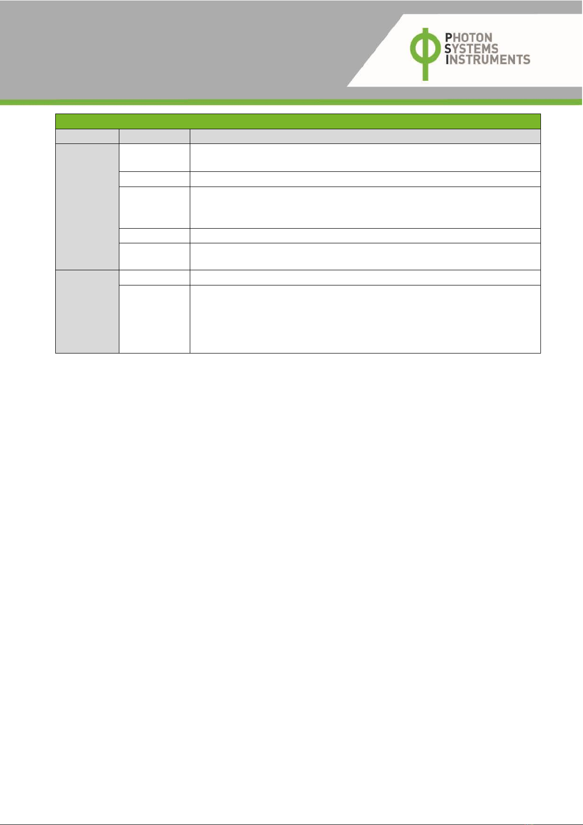
2.1.4 SUBSTITUTE CONNECTION CABLE
Substitute connection cable (4 Pin Male to USB 2.0 A Male) allows communication between the LaiPen device and the PC. The LaiPen
device is delivered with one connection cable included in price of device.
Fig. 5 Substitute connection cable

Page | 8
3TECHNICAL SPECIFICATIONS
LAI Pen 110
Measured and calculated
parameters
Photosynthetically active radiation (PAR, 400 –700 nm)
ALAI radiation (blue band of the spectrum, 400–500 nm)
PAR index calculated as PAR transmittance through canopy
ALAI index calculated as ALAI transmittance through canopy
Measurement at multiple
zenith angles:
0°, 16°, 32°, 48°, 64°
View Restricting Cap:
Horizontal field of view: 112°
Vertical field of view: 16°
Memory Capacity
16 MB
Internal Data Logging
Up to 100,000 data points
Actinic Illumination
Horizontal field of view: 112°
Detector Wavelength
Range:
PAR measurement: 400 –700 nm band pass filter
ALAI measurement: 400 - 500 nm band pass filter
Detector
PIN photodiode with bandpass filters
Data transfer
Connection cable
Bluetooth (transfer up to 3 Mbps for distance up to 20 m)
PC software
FluorPen
Battery
Li-Ion rechargeable battery
Capacity 2000 mAh
Max. charging current 0.5 A
Charging via USB port - PC, power bank, USB charger, etc.
48 hours typical with full operation, low battery indicator
Keypad
Sealed, 2-key tactile response
Turns off after 5 minutes of no use
Built in GPS module
Ultra-high sensitivity down to -165 dBm
High accuracy of < 1.5 m in 50 % of trials
Size
120 x 57 x 30 mm
Weight
180 g
Operating conditions
Temperature: 0 to +55 °C
Relative humidity: 0 to 95 % (non-condensing)
Storage conditions
Temperature: -10 to +60 °C
Relative humidity: 0 to 95 % (non-condensing)
Warranty
1-year parts and labor
Page | 9
Bluetooth module compliance data
Category
Country
Standard
Radio
USA
FCC Part 15 Subpart B: 2008 Class B
FCC CRF Title 47 Part 15 Subpart C
FCC ID:
T9J-RN42
Europe
ETSI EN 301 489-1 V1.8.1
ETSI EN 301 489-17 V2.1.1
ETSI EN 300 328 V1.7.1
Canada
IC RSS-210 low power comm. device
Certification
number:
6514A-RN42
EMC
USA
FCC CFR47 Part 15 subclass B
Europe
EN 55022 Class B radiated
EN61000-4-2 ESD immunity
EN61000-4-3 radiated field
EN61000-4-6 RF immunity
EN61000-4-8 power magnetic immunity
4PRINCIPLE OF MEASUREMENT
4.1 MEASURED PARAMETERS
Photosynthetically active radiation (PAR) is quantified as μmol photons m-2s-1, which is a measure of the photosynthetic photon flux
density (PPFD). The percent proportion of photosynthetic photon flux density (% PPFD) below a canopy can be interpreted as the canopy
PAR transmittance. PAR transmittance linearly correlates with canopy gap fraction, which is a parameter used to quantify probability of
solar radiation penetration through the canopy using photographs. LaiPen LP 100 can measure PAR irradiance with the use of PAR sensor
(see Fig.1) in a single wide angular detection range.
Leaf Area Index (LAI) is defined as one-sided green leaf area per unit ground surface area (LAI = leaf area/ ground area, m2/ m2) in
broadleaf canopies.
Although absorption of PAR by the vegetation canopy is sufficient for LAI calculation, LaiPen LP 100 is also offering to measure irradiance
of the blue part of solar radiation (400-500 nm) with LAI sensor (Fig.1). This irradiance, here designated as ALAI irradiance, is the most
efficiently absorbed part of the spectrum by green leaves, and therefore is more convenient for LAI calculation than PAR.
The LAI sensor is a single optical sensor used in conjunction with a view restriction cup (Fig.1) restricting the LAI sensor view to 160 (Z
axis) and 1120 angle (X axis). ALAI transmittance is measured by holding the instrument either vertically in zenith direction (i.e. zenith
angle 0°), or by subsequent inclination into five zenith angles: 0°, 16°, 32°, 48° and 64°.
LAI is then calculated from ALAI transmittance or PAR values after downloading the readouts from the LaiPen device to a computer
equipped with a spreadsheet software (e.g. MS Excel). Light transmittance below vegetation canopy (either PAR or ALAI) is then
calculated as irradiance from below the canopy divided by irradiance values from above or next to the canopy:
T = I /I0(Equation 1),
where I is irradiance intensity below the canopy, I0 is irradiance falling on vegetation (reference irradiance).
LAI is defined as the leaf area above the ground surface area: LAI = leaf area / ground area (units: m2/m2or ha2/ha2) and then can be
considered dimensionless. Methods of LAI determination, which are based on measuring irradiance intensity rely on the fact that
intensity of irradiance decreases exponentially when it passes through vegetation canopy according to Lambert-Beer extinction law
modified by Monsi - Saeki (Hirose, 2005):
I= I0e (–k LAI)(Equation 2), hence
LAI = - ln (I /I0)/ k (Equation 3), where
Page | 10
I is the irradiance intensity under the canopy, I0is the intensity of irradiance above the vegetation, e is Euler’s number and k is extinction
coefficient. Extinction coefficient is estimated from shape, orientation and position of each element of vegetation canopy with a known
inclination of canopy element and view direction (Breda, 2003).
As the values of extinction coefficient are usually close to 0.5 (e.g. Pierce and Running, 1988), the equation 3 can be simplified as
presented by Lang et al. (1991):
LAI = 2 |ln t| for inhomogeneous canopies (Equation 4) or
LAI = 2 |lnT| for homogeneous canopies (Equation 5),
where t is transmitance at each canopy measurement point and T is average transmitance of all t values per transect or stand.
After the initial calculation, LAI must be further corrected by proportion of woody elements surface area (WAI). Measurement below
canopy of coniferous trees requires further corrections of the LAI due to clumping of needles within shoots (Stenberg et al , 1999).
The initial LAI value uncorrected to the final value is often referred to effective LAI (LAIe). Correcting the LAIe
value to the final LAI value may not be always necessary (e.g. comparing groups with equal correction factors).
4.2 MEASURING REFERENCE
4.2.1 DISTANCE NEAREST SHADING OBSTACLE
Light transmittance through vegetation canopy is calculated from two irradiance values
T= I/I0 (Equation 1).
Irradiance measured below the canopy is divided by reference irradiance value measured either above the vegetation canopy or in an
open space without obstacles, which can cause shading. The reference measuring point in an open space depends on the view angle of
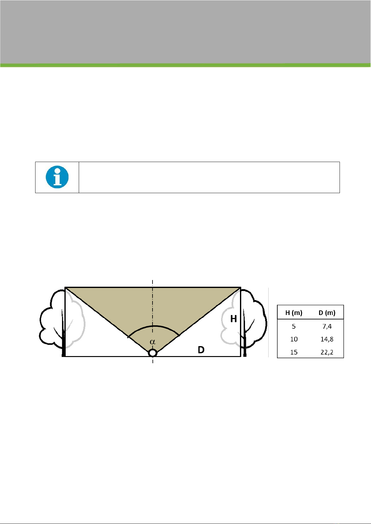
the light meter sensor (PAR or LAI) and the height of the nearest obstacle (see Fig. 6). The minimum recommended distance (D) for all
LaiPen reference measurements is approximately 1.5 multiple of the nearest obstacle height.
Fig. 6 Distance from the nearest obstacle.
Distance (D) from the operator (black circle) to the nearest obstacle (tree drawing) is dependent on the height of the nearest obstacle (H) and the
LaiPen maximum view angle α shown in grey (α=112˚). The enclosed table states minimum recommended distance values (D) for three obstacle heights
(H).
4.2.2 MEASUREMENT RELATIVE TO THE SUN
Measurement of ALAI irradiance with LAI sensor is dependent on field of view of the restricting cap. Since the angle of view is wide open
(112° in one axis), it is essential to prevent direct sunlight entering the view restriction cup. The overexposure of a LAI sensor could lead
to misinterpretation of actual light condition. Before each measurement, it is necessary to position the instrument as described in Fig. 7.
to obey the principle, that during measurement, the LAI sensor is never exposed to direct sunlight. Correct positioning of the LaiPen
relative to the sun does applies not only for obtaining correct reference values, but also for measurements below in-homogenous
canopies with incidental direct sunlight.

Page | 11
Fig. 7 Instrument positioning in relation to the sun position.
In order to prevent direct sunlight exposure of the LAI sensor, it is necessary to turn with the instrument around to correct position of the restriction
cup relative to the sun. Hold the instrument vertically and turn around with the device so the slot of the restriction cup is oriented perpendicularly to
sunlight direction and the front (display) side of the device would face the sun.
4.2.3 REFERENCE FOR SINGLE SENSOR MODE OF MEASUREMENT
In single sensor mode of measurement, reference readings are measured with the same instrument as the readings below canopy.
Reference readings are acquired before, after or even during the process of systematical measurement below the canopy. Transmittance
values are then calculated as dividing a canopy reading by a parallel reference value, which is estimated for the moment of canopy
reading. The parallel reference values are estimated as weighted average of two neighboring reference readings on the timeline (Fig. 8).

Page | 12
Single sensor mode of measurement is advised to be used preferably at constant light condition (clear or overcast
sky condition) as rapid changes of weather might cause inaccurate prediction of reference irradiance values,
which are necessary for correct LAI calculation.
Fig. 8 Calculation of reference values by FluorPen software in single sensor mode.
Reference values are computed as weighted average of two neighbouring reference readings on the timeline. Reference readings in this example were
taken before, after and during the measurement with the same instrument.Measured reference values, ⚫reference values estimated for light
transmittance calculation of canopy measurement.
4.2.4 REFERENCE FOR DUAL SENSOR MODE OF MEASUREMENT
In dual sensor mode of measurement two sensors are employed in parallel. One instrument is fixed in an open space for automatic
logging of reference readings in pre-defined time intervals, while the other instrument is used for hand-operated measurement under
the vegetation canopy (canopy readings). Transmittance values are then calculated as dividing a canopy reading by a parallel reference
value, which is estimated for the moment of canopy reading. The parallel reference values are estimated as weighted average of two
neighbouring reference readings on the timeline (Fig. 9). The dual sensor method collects considerable amount of reference data, thus
increases accuracy in estimation of reference values.
Fig. 9 Calculation of reference values by FluorPen software in dual sensor mode of measurement.
Reference values are computed as weighted average of two neighboring reference readings, which were acquired by automatic logging in 2 min
intervals. Automatic logging of reference readings, reference values estimated for each moment of canopy measurement. The estimates are then
used for calculation of light transmittance.
Page | 13
5GETTING STARTED
5.1 GENERAL GUIDE TO MEASUREMENT
This chapter explains how to start to operate the LaiPen LP110/USB in single sensor or in dual sensor mode of measurement. Single
sensor mode of measurement of ALAI irradiance can be used for measuring multiple angles, which is described in chapter 5.5. For more
detailed information on particular steps of LaiPen operation refer to chapter 5.
PAR can be measured with a PAR sensor, which is placed in the middle of the front side of the instrument (see Fig. 1). During measurement
the instrument must be placed horizontally with the PAR sensor facing upward (see Fig. 10, left panel).
ALAI irradiance is an irradiance of the blue part of visible spectrum and can be measured with a LAI sensor, which is placed on a side of
the LaiPen instrument. The LAI sensor is covered with a black restriction cup (see Fig. 1). Two modes of ALAI measurement in respect to
zenith angle are available. The single angle mode allows to obtain ALAI readings with LAI sensor pointing to zenith only (Fig. 6, right
panel). The multiple angle mode guides through measurement of five zenith angles: 0°, 16°, 32°, 48° and 64°. Operation instructions for
using the instrument in single angle or multiple angle mode are described in detail in chapters 5.3 - 5.5.
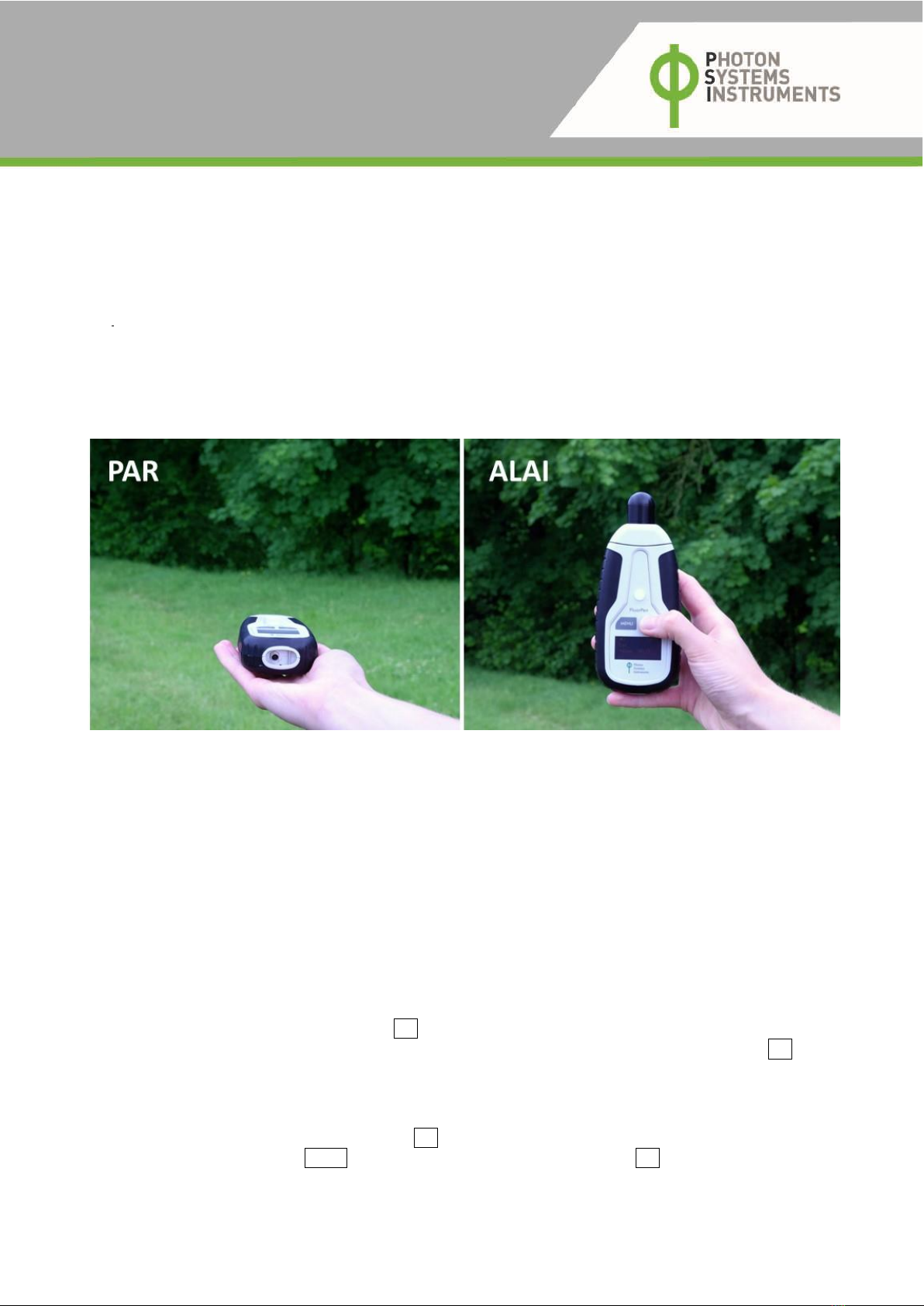
Fig. 10 Measurement of PAR and ALAI irradiance.
PAR irradiance is measured with horizontally oriented device (left), while ALAI irradiance is measured with ALAI sensor pointing upward (right).
Operation of the LaiPen can be enhanced with global positioning system. GPS receiver is switched on to receive satellite signal and then
the receiver is carried with the device during canopy measurement. The software can pair the irradiance readings with GPS coordinates
for each measuring point. For detailed instructions refer to chapter 11.
The following measurement procedures describe common methods of LAI determination from ALAI irradiance. For more detailed
information about the LaiPen software and how to handle acquired data refer to the chapters 6 to 9.
5.2 DARK CALIBRATION PRIOR TO MEASUREMENT
The LaiPen device should be calibrated for internal detector settings before each round of measurement or after switching ON the device.
Immediately after completion of each calibration procedure zero value appears on the display indicating successful calibration. Set the
internal date and time Main Menu > Settings > Time before first measurement or after battery replacement.
Prior to each measurement calibrate the LAI optical sensor to the dark. Before starting the dark calibration procedure prepare a piece of
dark cloth.
1. Switch on the instrument by pressing and holding SET button for 1 second.
2. Select Main Menu > Settings > LAI Cal and check whether the LAI calibration constant is set to 1 (c = 1.0), if not press SET repeatedly
to adjust the constant to 1.0. This feature allows to adjust detector settings of one instrument to another, which is used for dual
sensor mode of measurement. In case of measuring in single sensor mode keep the constant set to 1.0 for all measurements.
3. Select Main Menu > Settings > LAI Zero. Cover the front LAI sensor competely with dark thick cloth or simply by a thumb and hold it
tightly during the process of calibration to ensure complete darkness. It is important that no surrounding light can interfere with the
measurement during the calibration step. Then press SET and stable zero value appears on the display.
4. To return to the main menu press MENU repeatedly until Return is selected and then press SET.

Page | 14
5.3 SINGLE SENSOR MODE OF MEASUREMENT
This chapter describes a particular measurement procedure with single LaiPen instrument operating in one zenith angle. Example in
chapter 5.6 describes how to perform the zenith angle measurements systematically to determine LAI in vegetation cover.
It is advised to use single sensor mode of measurement preferably at constant light conditions as rapid changes
of weather can cause inacurate LAI calculation.
1. Switch on the instrument by holding SET button for 1 second.
2. Calibrate the LaiPen to the dark condition (see chapter Error! Reference source not found.)
3. Set the LaiPen or make sure it is set to single angle mode of measurement Main Menu > Settings > Angles > Single
4. If you want to use GPS device, turn it on and carry the device during all canopy measurements with the LaiPen device (see chapter
6).
5. Take reference measurement in an open space. In sunny weather condition avoid entering direct sunlight into the view restricting
cup (see chapter 4.2.2).
5.1. Set Main Menu > Measure > ARef after pressing SET online measurement of reference value is activated. Irradiance value is
continuously monitored, actual value appears on the display. Please note that these values are not stored to internal memory
of the device.
5.2. To acquire reference value, which must be obtained in the zenith angle, follow the next step. Press SET again to start the
navigation for obtaining the zenith angle position of the ALAI sensor. Reference value is automatically acquired and stored.
Internal inclinometer and acoustic beeping indicator are activated. Readings of angle degrees for current position of Lai sensor
appear on the display for both X and Z axis. Angle of the zenith position, which is necessary for LAI measurement is defined by
X and Z axis equal to 0.
5.3. Then place the LaiPen vertically with the ALAI sensor pointing up to the zenith. The acoustic indicator would switch from low
tone to high tone beeping when the current position of the instrument is reaching an angle, which is close to the target (zenith).
5.4. Watch the display, tilt the instrument in left-right direction and in forward-backward direction to achieve the lowest angle for
both readings (X and Z axis) and carefully try to reach the zenith angle. This step can be sometimes tedious since the correct
position must be achieved in range of milometers.
5.5. Reference measurements proceed automatically, when the correct position is reached. This is indicated by increased frequency
of beeping after which beeping tone is interrupted. At the same time the measured value is displayed temporarily in format
“REF X = value”, where X is the measurement number and the value is stored to internal memory. Then the instrument would
switch back to continuous reading mode.
6. In the next step transmittance measurement under the canopy is described. Define position under the vegetation canopy and start
the ALAI value measurements.
6.1. Go to Main Menu > Measure > ALAI. After pressing SET online measurement of ALAI irradiance is activated. Irradiance value is
continuously monitored, actual value appears on the display. These values are not stored to internal memory of the device.
6.2. To acquire ALAI value, which must be obtained in the zenith angle, follow the next step. Press SET again to start the navigation
for obtaining the zenith angle position of the ALAI sensor. ALAI values are automatically acquired and displayed. First, internal
inclinometer and acoustic beeping indicator are activated. Detailed readings of angle degrees to zenith direction appear on the
display for both X and Z axis.
6.3. Then position the LaiPen vertically with the Lai sensor pointing up to the zenith. The acoustic indicator would switch from low
tone to high tone beeping when the position of the instrument is reaching an angle, which is close to the target (zenith).
6.4. Watch the display, tilt the instrument in left-right direction and in forward-backward direction to achieve the lowest angle for
both readings (X and Z axis) and carefully reach the zenith angle. This step can be sometimes tedious since the correct position
must be achieved in range of millimeters.
6.5. Measurement proceeds automatically, when the correct position is reached. This is indicated by increased frequency of beeping
after which beeping tone is interrupted. At the same time the measured value is displayed temporarily in format “ALAI X =
value”, where X is the measurement number and the value is stored to internal memory. Then the instrument would switch
back to continuous reading mode.
7. Proceed to further ALAI measurements under vegetation canopy. You can also measure reference values anytime in between the
ALAI measurements (e.g. after completion of each transect); it will increase precision of the reference value prediction.

Page | 15
8. Soon after completing measurement under vegetation canopy obtain the last reference value in an open space.
9. To return to the main menu press MENU repeatedly until Return is selected and then press SET.
10. After each measurement the data is stored to the device internal memory and the instrument can be switched off by holding MENU
button for 1 second safely without erasing data.
11. Connect the instrument to computer and download data (see chapter 9.3). For example, of field measurement and LAI calculation
refer to chapter 4.6.
5.4 DUAL SENSOR MODE OF MEASUREMENT
In dual sensor mode of measurement one instrument is fixed on a tripod and used for automatic logging of reference signal in pre-defined
time interval (instrument_1). The other instrument is used for hand-operated measurements below vegetation canopy (instrument_2).
Example in chapter 4.6 describes how to perform zenith angle measurements for subsequent LAI calculation in vegetation cover.
1. Switch on both instruments by holding SET button for 1 second and set the actual date and time if necessary (Main Menu >
Settings > Time). Instrument_1 will be used for reference measurements, instrument_2 for canopy measurements.
2. Calibrate the both LaiPen instruments to the dark condition (see chapter 5.2).
3. Set both the instruments to single angle mode of measurement Setting > Angles > Single.
4. For dual sensor mode it is essential that detectors of both instruments are set to same value prior measurement. Log the reference
value with both instruments (instrument_1 and instrument_2). Go to Main Menu > Measure > ARef and press SET. After pressing
SET online measurement of reference value is activated. Irradiance is continuously monitored. These values are not stored to
internal memory of the device.
5. Use the displayed reference values from the instrument_2 to adjust calibration constant of the instrument_1 to achieve the same
reference value as displayed on the instrument 2. Go to Settings > LAI Cal and by repeatedly pressing SET adjust the C value and
the same reference readings (I value) appears on both instruments.
6. Set the instrument_1 in an open space for automatic logging of reference signal.
6.1. Go to Main Menu > Settings > AutoRef to define the repetition time for automatic measurement on the instrument_1.
6.2. Set a tripod in an open space (see chapter 4.2.1) and mount the instrument_1 to the tripod loosely, in horizontal (PAR
measurement) or vertical (ALAI measurement) position.
6.3. Set the instrument_1 to automatic mode of reference measurement. Go to Measure > AutoARef and press SET to start the
navigation for obtaining zenith angle position of the LAI sensor. In case of PAR measurement go to Measure > AutoPRef and
press SET.
6.4. Position the LaiPen vertically with the LAI sensor pointing up to the zenith or horizontally for PAR measurement. In case of
measurement of ALAI transmittance avoid entering direct sunlight into the view restricting cup (see chapter and 4.2.2) during
the process of measurement in sunny weather condition.
6.5. Watch the display, tilt the instrument in left–right direction and in forward–backward direction to achieve the lowest angle
for both axis angle eadings. This step can be sometimes tediuos since the correct position must be achieved in range of
milimeters. After reaching the correct position tighten the LaiPen instrument to the tripod firmly.
6.6. Press SET again. Reference values are automatically acquired and displayed in format “REF X = value”, where X is the
measurement number.
7. In this step transmittance measurement with the instrument_2 under the canopy is described.
7.1. Define position below the vegetation canopy for ALAI or PAR canopy irradiance measurement.
7.2. Go to Main Menu > Measure > ALAI or Main Menu > Measure > PAR and press SET to activate online measurement of
irradiance. Irradiance is continuously monitored; actual reading appears on the display. These values are not stored to
internal memory of the device.
7.3. Press SET again to obtain ALAI or PAR value, which are acquired automatically in the following procedure. First, internal
inclinometer and acoustic beeping indicator are activated. Detailed readings of angle degrees to zenith direction appear
on the display for both axis.
7.4. Place the LaiPen vertically with the Lai sensor pointing up to the zenith. The acoustic indicator would change from low
tone to high tone beeping when the current position of the instrument_2 is reaching angle close to the correct zenith
angle.
Page | 16
7.5. Watch the display, tilt the instrument in left-right direction and in forward-backward direction to achieve the lowest angle
for both axis angle readings. This step can be sometimes tedious since the correct position must be achieved in range of
milometers.
7.6. Measurement proceeds automatically, when the correct position is reached. This is indicated by increased frequency of
beeping after which beeping tone is interrupted. At the same time the display shows in first row number of measurements
in format “ALAI (PAR) X” where X is the measurement number and in the second row the irradiance value in format “I =
value”. The readings are stored to LaiPen memory and the instrument switches back to continuous reading mode.
8. After each measurement the data is stored to the device internal memory and the instrument can be switched off by holding MENU
button for 1 second safely without erasing data.
9. To return to the main menu press MENU repeatedly until Return is selected and then press SET. Connect the instruments to
computer and download the data as described in chapter 9.
5.5 MULTIPLE ANGLE MODE OF MEASUREMENT
In this chapter protocol with single LaiPen instrument measuring irradiation in five zenith angles is described.
Multiple angle mode is used for measurement only with the LAI sensor.
1. Switch on the instrument by holding SET for 1 second and set the actual date and time if necessary (Main Menu > Settings > Time).
2. Calibrate the instrument to the dark (see chapter 5.2).
3. Set the LaiPen (or make sure it is set) to multiple angle mode of measurement Main Menu > Settings > Angles > Multiple.
4. If you want to use GPS device, turn it on and carry the device during all canopy measurements with the LaiPen device (see chapter
6).
5. Take reference measurement in an open space. In sunny weather condition avoid entering direct sunlight into the view restricting
cup (see chapter 4.2.2).
5.1. Set Main Menu > Measure > ARef Press SET to activate immediate measurement of reference values. Irradiance value is
continuously monitored, actual value appears on the display. Please note that these values are not stored to internal
memory of the device.
5.2. Press SET again to start the navigation to acquire reference values. Reference values must be obtained in all five zenith
angles of the LAI sensor subsequently. Internal inclinometer and acoustic beeping indicator are activated and all five
subsequent measurements proceed automatically, when the correct position of individual angles are reached. The correct
position from the target angle is indicated as 00angle at both x and z axis with tolerance 50. Readings of angle degrees for
current position of Lai sensor appear on the display for both X and Z axis. This step can become quite tedious since the
correct position must be achieved in range of milometers.
5.3. Place the instrument in horizontal position, watch the display and tilt the instrument slowly in vertical direction while
keeping the LAI sensor facing upward. The acoustic indicator would change from low tone to high tone beeping when the
position of the instrument reaches angle close to the first target at 64°. Tilt the instrument to achieve the lowest angle
for both readings (X and Z axis). Interruption of the high tone beeping and switching to low tone beeping indicates
completion of measurement of the target value.
5.4. Watch the display and tilt the instrument slightly more vertically to achieve the lowest angle for both readings (X and Z
axis). The acoustic indicator would switch from low to high tone when the position of the instrument is reaching angle
close to the second target angle value (48°). Interruption of the high tone beeping and switching to low tone beeping
indicates completion of measurement of the second value.
5.5. Repeat the previous step for the remaining three angles 32°, 16° and 0° (zenith angle).
Neither target angle values (640, 480, 320, 160, 00), nor readings are shown on the display during measurement.

Page | 17
6. In the next step measurement under the canopy is described. Define position under vegetation canopy and start the ALAI
measurement.
6.1. Set Main Menu > Measure > ALAI Press SET to activate immediate measurement of reference values. Irradiance value is
continuously monitored, actual value appears on the display. Please note that these values are not stored to internal
memory of the device.
6.2. Press SET again to start the navigation to acquire reference values. Reference values must be obtained in all five zenith
angles subsequently. Internal inclinometer and acoustic beeping indicator are activated to obtain each zenith angle of
the Lai sensor. All five subsequent measurements proceed automatically, when the correct position of individual angles
are reached. The correct position from the target angle is indicated as 00angle at both x and z axis with tolerance 50.
Readings of angle degrees for current position of ALAI sensor appear on the display for both X and Z axis. This step can
become quite tedious since the correct position must be achieved in range of milometers.
6.3. Place the instrument in horizontal position, watch the display and tilt the instrument slowly in vertical direction while
keeping the ALAI sensor facing upward. The acoustic indicator would change from low tone to high tone beeping when
the position of the instrument reaches angle close to the first target at 64°. Tilt the instrument to achieve the lowest angle
for both readings (X and Z axis). Interruption of the high tone beeping and switching to low tone beeping indicates
completion of measurement of the target value.
6.4. Watch the display and tilt the instrument slightly more vertically to achieve the lowest angle for both readings (X and Z
axis). The acoustic indicator would switch from low to high tone when the position of the instrument is reaching angle
close to the second target angle value (48°). Interruption of the high tone beeping and switching to low tone beeping
indicates completion of measurement of the second value.
6.5. Repeat the previous steps analogically for other three angles 32°, 16° and 0° (zenith angle).
Neither target angle values (640, 480, 320, 160, 00), nor readings are shown on the display during measurement.
7. After completion of all intended measurements return to the main menu press MENU repeatedly until Return is selected and then
press SET.
8. After each measurement the data is stored to the device internal memory and the instrument can be safely switched off by holding
MENU button for 1 second safely without erasing data.
9. Connect the LaiPen to computer and download the data (see chapter 9).
5.6 EXAMPLE OF ZENITH ANGLE MEASUREMENT AND LAI CALCULATION
1. Define measurement points for canopy measurement. The points can be arranged in a grid or transects to surpass vegetation cover
inhomogeneity caused by different canopy gaps etc. A suitable layout of transects helps to fix the distance (e.g. three steps)
between measurement points and proportionally characterize all the diverse parts in vegetation cover. An example of a suitable
transect layout in homogenous vegetation cover planted in rows is shown in Fig. 11.
2. Measure the first reference value in an open space in zenith direction as described in chapter 5.6. All the following measurements
(i.e. above- and below-canopy) will be done with the same method in zenith direction.
3. Measure ALAI irradiance below vegetation at each position of the transect course (see chapter 4). You can measure reference
values in an open space anytime during the measurement (e.g. after completion of each transect measurement).
4. Take the last reference value in an open space.
5. After finishing the measurements download the data to computer using FluorPen software and export the data as described in
chapter 9.4.
Although the current version of FluorPen software automatically calculates ALAI transmittance when
downloaded from the LaiPen to computer it fails to add the transmittance values to exported file.
Page | 18
6. Calculate ALAI transmittance according to equation T = I /I0(equation 1) from irradiance values, which you can obtain after opening
the exported file in a spreadsheet software (e.g. MS Excel, see chapter 5). Calculate ALAI transmittance using the spreadsheets by
dividing the exported iradiance values below the canopy (I) named “value” by reference irradiance values predicted for each time of
canopy measurement (I0) named “ref.”. Each measurement is calculated separately as ALAI1 = value1/ ref1, ALAI2=value2/ ref2, ALAIn=
=valuen/ refn, where n is the number of below-canopy measurements.
7. Calculate logarithm of transmittance values.
a. In case of inhomogeneous cover calculate logarithm of transmittance in each canopy measurement point ln(ALAI1),
ln(ALAI2), ... ln(ALAIn). Then calculate the average value of all logarithms in the first transect T_1 as ln(ALAII) = [ln
(ALAI1) + ln (ALAI2)…+ ln (ALAI10)]/ 10. Proceed with remaining transects in a similar way.
b. In case of homogeneous cover calculate an average ALAI transmittance for the first transect as ALAII= (ALAI1+ ALAI2
... + ALAIn)/n) and then calculate logarithm of the average ALAI transmittance in the first transect T_1 as ln (ALAII).
Proceed with remaining transects in a similar way.
8. Calculate the final average logarithm of ALAI transmittance in entire vegetation cover ln(ALAI) = [ln (ALAII) + ln (ALAIII) + ln
(ALAIIII) + ln (ALAIIV)]/4).
9. Nominate extinction coefficient kand calculate LAI by dividing the resulting value with k,thus: LAI = (1/k) |ln(ALAI)|. With the
most frequent value of extinction coefficient k= 0.5 the LAI would be calculated as LAI = 2|ln (ALAI)|. For more information
refer to chapter 3.1.
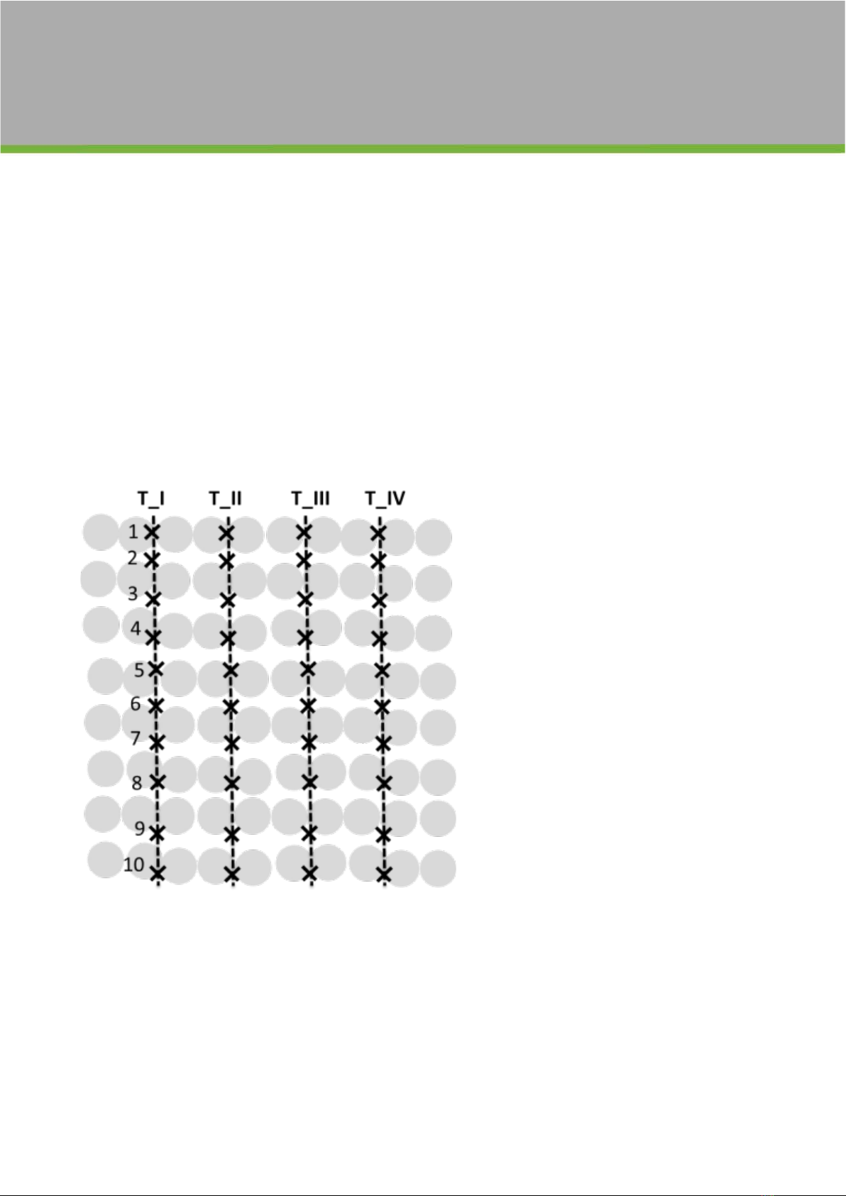
Fig. 11 Schematic drawing of transects (T) in vegetation cover.
Plants, which are planted in rows are represented by horizontal lines of gray spots. Each measurement point () is indicated along transects (from T_I
to T_IV). The first ten points in T_I are numbered 1- 10. Note that transects are arranged perpendicularly to the rows of plants.
Page | 19
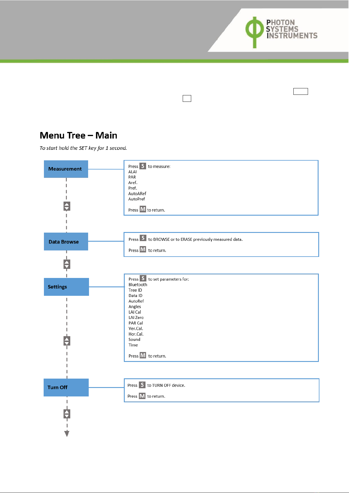
6CONTROL MENU TREE
To switch ON the device, hold the SET key for 1 second. Use the control menu tree to perform the measurements. Use the MENU button
to scroll through sequential menu options on the digital display. Use SET button to select an option indicated with the cursor position
(˃). The following diagrams describe the structure of the Menus (Fig. 12Error! Reference source not found. - Fig. 16) with all available
options.
Switch OFF the device after use by holding the MENU button for 1 second.
Fig. 12 Main Menu.
Page | 20
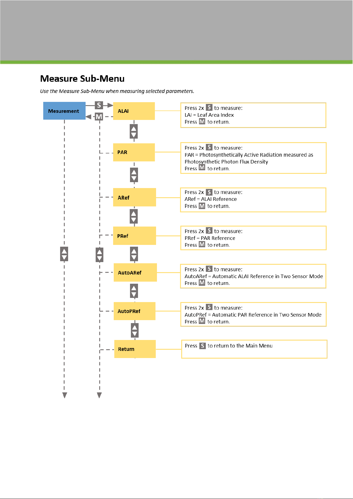
Fig. 13 Measure Sub Menu.
Table of contents
Other PSI Measuring Instrument manuals


