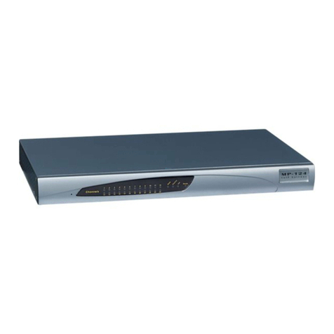
Wieland gesis KNX FLEX-ENO32B User manual

Montageanleitung (Original) /
Installation instruction (translation from original)
gesis®
KNX FLEX-ENO32B
3.020.062 .2
EnOcean-KNX-Gateway 32 Kanäle /
EnOcean-KNX-Gateway 32 channels
Wieland Electric GmbH
Brennerstraße 10 – 14
96052 Bamberg
Phone +49 951 9324-0
Fax +49 951 9324-19
info@wieland-electric.com
www.wieland
-
electric.com
Doc. # BA001165 – 11/2020 (Rev. B) gesis® KNX FLEX-ENO32B 1 DE / EN
W A R N U N G
•
Nur Elektrofachkräfte dürfen dieses Gerät installieren und in Betrieb nehmen. Vor
Ausführung müssen sie diese Anleitung gelesen und verstanden haben.
•Nur in spannungsfreiem Zustand anschließen oder trennen!
•Das Gerät darf nicht geöffnet werden! Führen Sie keine Fremdobjekte in das Gerät ein!
•Halten Sie das Gerät von Wasser und Feuer fern!
•Die einschlägigen Normen, Richtlinien, Vorschriften und Bestimmungen des jeweiligen
Landes sind zu beachten.
Das bidirektionale EnOcean-KNX-Gateway für 32 Kanäle ist ein eigenständiges Gerät im auf
Tragschienen montierbaren AP-Gehäuse zum dezentralen Einbau. Das Gateway orientiert
sich an den EnOcean-Equipment-Profilen (EEP). Neben einer Software zur Inbetriebnahme
steht eine komfortable Handbedienung über ein Display zur Verfügung. Die ETS-Applikation
verfügt zusätzlich über einen umfangreichen Logik/Regelbereich. Die KNX-Verbindung ist
steckbar ausgeführt.
1Bedien- und Funktionselemente (siehe Rückseite, Abbildung 1)
Pos.
Name
Beschreibung
1
Taster 'KNX'
Startet den Programmiermodus. (Details: siehe Handbuch)
2
LED 'KNX'
Leuchtet im Programmiermodus rot.
3
Display
Zeigt im Hauptmenü:
Gerätename, Betriebsmodus, physikalische KNX
-
Adresse
4
Antenne
Externe Antenne mit Magnetfuß für optimalen Empfang der
Funktelegramme
5
Eingang
KNX
-
Bus
Anschluss mit Buchse BST14i2, 2
-
polig, grüne Codierung
(Montage: siehe Rückseite, Abbildung 3)
6
Ausgang
KNX
-
Bus
Anschluss mit Stecker BST14i2, 2
-
polig, grüne Codierung
(Montage: siehe Rückseite, Abbildung 3)
7
Taster
'exit/delete'
•
Kurzer Tastendruck: Kanal
-
oder Lernmodus verlassen.
Wechselt zur Startseite oder bei weiterem kurzem Tastendruck in
den Busmonitor.
•
Tastendruck >1 s: Ermöglicht das Löschen der eingelernten
Funkverknüpfung. (Details: siehe Handbuch)
Taster
'activate/add'
•
Kurzer Tastendruck: Anwahl der Kanäle 1 bis 32
•
Tastendruck >1 s: Startet den Lernmodus. (Details: siehe Handbuch)
2Montage (siehe Rückseite, Abbildung 2)
Schritt 1 Optional Befestigung auf Tragschiene oder Montagerahmen
1.1
Am Modul mit Schraubendreher den Rastfuß nach oben ziehen.
1.2
Das Modul auf Tragschiene aufsetzen.
1.3
Am Modul mit Schraubendreher den Rastfuß nach unten drücken.
Das Modul ist auf der Tragschiene befestigt.
Schritt 2 Kabel stecken un sichern sowie Antenne montieren
2.1
Kabel am Modul stecken.
Wichtig: Festen Sitz aller Steckverbindungen sicherstellen.
2.2
Bei Montagerahmen: Kabel mit Kabelbindern am Montagerahmen fixieren.
2.3
Antenne mit Magnetfuß an geeigneter Stelle anbringen.
Wichtig: Elektrisch leitfähige Gegenstände in mittelbarer oder unmittelbarer Nähe vom
Empfangsbereich der Stabantenne beeinflussen die Empfangs- und Sendeeigenschaft
des Geräts. Eine Beeinträchtigung der Reichweite ist die Folge.
3Technische Daten
Spannungsversorgung
über KNX
-
Bus
Stromaufnahme
ca. 12 mA
Spannung
2
4
V
DC
SELV
EnOcean
Schnittstelle
ISM Band 6 ,3 MHz, ASK
Reichweite
max. 30 m (Umgebungsabhängig siehe
www.enocean.com
)
Sendeleistung max.
max.
+ 5,6 dBm (typisch +3 dBm)
Unterstützte Geräte
EnOcean Equipment Profile
KNX
KNX
-
TP steckbarer Busanschluss BST14i2
Umweltbe ingungen
Einsatzbereich
Innenräume und trockene Räume, wettergeschützt
Klimabeständigkeit
Klasse 3K5 (EN 50491
-
2)
Umgebungstemperatur
-
5 °C bis +45 °C
Lagertemperatur
-
25 °C bis +75 °C
Montageart
Decken
-
, Boden
-
, Wandmontage, feste
Installation, Aufputz, auf
ebene Fläche, Tragschiene TH35, Montagerahmen
Gehäuse
Material
Kunststoff, halogenfrei
Farbe
Lichtgrau, ähnlich RAL 7035 / Schwarz, ähnlich RAL 9005
Brandverhalten
Brandlast
UL94 V
-
2
ca. 2 kWh
Abmessungen (B×H×L)
127 × 149 ×
44 mm
Elektrische Sicherheit
Schutzklasse / Schutzart
III / IP20 (nach EN 60529)
Zulassungen
CE
-
Kennzeichnung
Gemäß EMV
-
, RED
-
, R
o
HS
-
Richtlinie
Erfüllt Normen: EN 50491-5-1, EN 50491-5-2, EN 50491-5-3
ETSI EN 300220
-
2
CE:
Hiermit erklärt Wieland Electric GmbH, dass das Produkt
gesis®
KNX FLEX
-
ENO32B
mit
den folgenden europäischen Anforderungen übereinstimmt:
RED Richtlinie 2014/53/EU, RoHS-Richtlinie 2011/65/EU.
Die vollständige EU-Konformitätserklärung ist mit der jeweiligen Teilenummer unter z. B.
https://eshop.wieland-electric.com/products/ 3.020.062 .2 im Register "Downloads"
abrufbar.
Handbuch
mit
detaillierten Informationen zu Programmierung, Inbetriebnahme und
Wartung:
•
Dokumentnummer: BA000903
•
Download über QR-Code oder:
http://eshop.wieland-electric.com/product/ 3.020.062 .2
W A R N I NG
•
Only trained electricians may install and commission this device. They must have read
and understood this instruction manual before they carry out installation.
•Only connect or disconnect the device when de-energized!
•The unit must not be opened! Do not insert foreign objects into the device!
•Keep the device away from water and fire!
•The relevant standards, directives, regulations and provisions of the particular country
are to be observed.
The bidirectional EnOcean-KNX-Gateway for 32 channels is a stand-alone device in an AP
housing mounted on carrier rails for decentralized installation. The gateway is patterned
after the EnOcean Equipment Profiles (EEP). In addition to start-up software, there is a
convenient manual control display available for use. The ETS application also includes a
comprehensive logic/control area. The KNX connection is designed as a plug.
1Operating and functional elements (see back, Figure 1)
Pos.
Name
Description
1
'KNX' button
Starts the programming mode.
(For
details: See manual)
2
'KNX' LED
Lights up red in programming mode.
3
Display
Shown in the main menu:
Name of equipment, operating mode, physical KNX address
4
Antenna
External antenna with magnetic base for optim
al
recept
ion
of radio
telegrams
5
Input
KNX bus
Connection with socket BST14i2, 2
-
pin, green coding
(installation: see reverse side Figure 3)
6
Output for
KNX bus
Connection with plug BST14i2, 2
-
pin, green coding
(installation: see reverse side Figure 3)
7
'exit/delete'
button
•
Short button press: leaves the channel or learning mode.
Switches to the start page or with another short button press goes
to the bus monitor.
•
Button press >1 s: enables deletion of the learned radio link. (For
details: see manual)
'ac
tivate/add'
button
•
Brief button press: select channels 1 to 32
•
Button press >1 s: starts the learning mode.(For details: see manual)
2Installation (see back, Figure 2)
Step 1 Optional Fastening on carrier rail or mounting frame
1.1
Pull the resting foot on the module upwards with a screwdriver.
1.2
Set the module onto the carrier rail.
1.3
Press the resting foot on the module downwards with a screwdriver.
The module is now fastened on the carrier rail.
Step 2 Plugging in cables and securing them and installing antennas
2.1
Plug in cable at the module.
Important: Ensure that all plug-in connections are securely seated.
2.2
For mounting frames: Fix to mounting frame with cable binders.
2.3
Attach antenna at a suitable place with magnetic foot.
Important: Electrically conducting objects in the direct or indirect vicinity of the receiving
area of the bar antenna can affect the reception and transmission quality of the
equipment. This can negatively affect the range.
3Technical data
Power supply
through KNX bus
Current consumption
about 12 mA
Voltage
24 V DC SELV
EnOcean
Interface
ISM Band 6 .3 MHz, ASK
Range
max. 30 m (depending on environment, see
www.enocean.com
)
Transmitting power
max. + 5.6 dBm (typical +3 dBm)
Supported devices
EnOcean Equipment Profile
KNX
KNX
-
TP pluggable bus connection BST14i2
Environmental con itions
Area of application
Internal rooms and dry rooms, protected from weather
Climate resistance
Class 3K5
(EN 50491
-
2)
Ambient temperature
-
5
°C to +45
°C
Storage temperature
-
25
°C to +75
°C
Type of installation
Installation on ceiling, floor and wall, fixed installation, surface
-
mounted, on level surface, carrier rail TH35, mounting frame
Housing
Material
Plastic, halogen
-
free
Color
Light grey, similar to RAL 7035 / Black, similar to RAL 9005
Reaction to fire
Fire load
UL94 V
-
2
approx. 2 kWh
Dimensions (W×H×L)
127 × 149 × 44 mm
Electrical safety
Protection class / type
III / IP20 (in
accordance with EN 60529)
Approvals
CE marking
In accordance with EMC, RED, R
o
HS
d
irective
Meets standards: EN 50491-5-1, EN 50491-5-2, EN 50491-5-3
ETSI EN 300220
-
2
CE:
Hereby, Wieland Electric GmbH declares that the
gesis®
KNX FLEX
-
ENO32B
is in
compliance with the following European directives:
RED directive 2014/53/EU, RoHS directive 2011/65/EU.
The complete EU Declaration of Conformity is available with the respective part number
under e.g. https://eshop.wieland-electric.com/products/ 3.020.062 .2 in the register
"Downloads".
Manual
with detailed information on programming, commissioning and
maintenance:
•
Document number: BA000904
•
Download via QR code or:
http://eshop.wieland
-
electric.com/product/ 3.020.062 .2
DE
EN

Montageanleitung (Original) /
Installation instruction (translation from original)
gesis®
KNX FLEX-ENO32B
3.020.062 .2
EnOcean-KNX-Gateway 32 Kanäle /
EnOcean-KNX-Gateway 32 channels
Wieland Electric GmbH
Brennerstraße 10 – 14
96052 Bamberg
Phone +49 951 9324-0
Fax +49 951 9324-19
info@wieland-electric.com
www.wieland
-
electric.com
Doc. # BA001165 – 11/2020 (Rev. B) gesis® KNX FLEX-ENO32B 2 DE / EN
Abbil ung 1: Be ien- un Funktionselemente /
Figure 1: Operating an functional elements
Abbil ung 2: Montage es Mo uls /
Figure 2: Mo ule installation
Abbil ung 3: Montage Buchse/Stecker BST14i2 (93.421.0553.1/ 93.422.00553.1) Figure 3: Installation of socket/plug BST14i2 (93.421.0553.1/ 93.422.00553.1)
1.
Kabel abisolieren und ablängen.
1.
Remove the insulation and cut to length.
2.
Buchse/Stecker aufklappen und Drähte in Federkraftkontakte einführen.
(rot = Plus; schwarz = Minus)
2.
Flip open the socket/plug and lead in wires to the spring contacts.
(red = plus; black = minus)
3.
Buchse/Stecker zuklappen und mit hörbarem Klick einrasten.
4.
Fold socket/plug closed and latch with audible click.

Notice de montage (traduction de l'original) /
Istruzioni per l'installazione (traduzione dall'originale)
gesis®
KNX FLEX-ENO32B
3.020.062 .2
Passerelle EnOcean-KNX 32 canaux /
EnOcean-KNX-Gateway 32 canal
Wieland Electric GmbH
Brennerstraße 10 – 14
96052 Bamberg
Phone +49 951 9324-0
Fax +49 951 9324-19
info@wieland-electric.com
www.wieland
-
electric.com
Doc. # BA001165 – 11/2020 (Rev. B) gesis® KNX FLEX-ENO32B 3 FR / IT
A V E R T I S S M E N T
•
Seuls les électriciens spécialisés sont autorisés à installer cet appareil et à le mettre en
service. Avant de commencer, ils doivent avoir lu et compris ces instructions.
•Ne raccorder l'appareil ou ne le déconnecter que lorsqu'il n'est pas sous tension.
•Ne pas ouvrir l'appareil. Ne pas insérer d'objets tiers.
•Tenir l'appareil éloigné de l'eau et du feu.
•Respecter les normes, directives, prescriptions et dispositions applicables dans chaque
pays.
La passerelle bidirectionnelle EnOcean-KNX pour 32 canaux est un dispositif autonome
dans un boîtier en saillie à monter sur un rail porteur pour le montage décentralisé. La
passerelle se fonde sur le profil EEP (EnOcean Equipement Profile). Outre le logiciel de mise
en service, l'équipement propose une commande manuelle confortable via l'écran.
L'application ETS dispose par ailleurs d'une rubrique logique/de règles complète. La liaison
KNX est enfichable.
1Éléments de commande et de fonction (voir verso, figure 1)
N°
Nom
Description
1
Bouton 'KNX'
Démarre le mode de programmation.
(Détails
: voir la notice)
2
LED 'KNX'
S'allume en rouge dans le mode de
programmation.
3
Écran
Menu principal
:
Nom de l'appareil, mode de fonctionnement, adresse physique KNX
4
Antenne
Antenne externe avec pied magnétique pour la réception optimale des
télégrammes radio
5
Entrée
Bus KNX
Raccordement avec la prise
BST14i2, 2
pôles, codage vert
(Montage
: voir verso, figure
3)
6
Sortie du bus
KNX
Raccordement avec le connecteur BST14i2, 2
pôles, codage vert
(Montage
: voir verso, figure
3)
7
Bouton
'exit/delete'
•
Appui court sur la touche
: quitter le mode canal
ou
d'apprentissage.
Passe à la page de démarrage ou dans l'écran du bus après un appui
court consécutif.
•
Appui sur la touche > 1 s : permet de supprimer la liaison radio
programmée.
(Détails
: voir manuel)
Bouton
'activate/add'
•
Appui court sur la
touche
: sélection des canaux 1 à 32
•
Appui sur la touche > 1 s : démarre le mode d'apprentissage.
(Détails
: voir manuel)
2Montage (voir verso, figure 2)
2.1 Étape 1 En option fixation sur un rail porteur ou un cadre de montage
1.1
Tirer le pied encliquetable vers le haut sur chaque module à l'aide d'un tournevis.
1.2
Placer les modules sur le rail porteur.
1.3
Pousser le pied encliquetable vers le bas à l'aide d'un tournevis sur chaque module.
Le module est fixé sur le rail porteur.
Étape 2 Enfichage du câble et fixation
2.1
Raccorder le câble au module.
Important : S'assurer de la bonne fixation de tous les raccords enfichés.
2.2
Avec cadre de montage : Fixer les câbles sur le cadre de montage à l'aide de serre-
câbles.
2.3
Placer l'antenne à l'emplacement approprié à l'aide du pied magnétique.
Important : des dispositifs conducteurs à proximité immédiate ou à moyenne distance
de la zone de réception de l'antenne influencent les propriétés de réception et d'émission
de l'appareil. La portée s'en trouve entravée.
3Caractéristiques techniques
Alimentation en tension
via le bus KNX
Courant absorbé
env. 12
mA
Tension
24
VCC TBTS
EnOcean
Interface
Bande ISM 6 ,3
MHz, ASK
Portée
max. 30
m (en fonction de l'environnement, voir
www.enocean.com
)
É
nergie d'émission
max. +5,6 dBm (typique +3 dBm)
Appareils pris en charge
EnOcean Equipment Profile
KNX
KNX
-
TP raccord de bus enfichable BST14i2
Con itions ambiantes
Zones d'utilisation
Espaces
intérieurs et locaux secs, protégés contre les
intempéries
Résistance à l'environnement
Classe 3K5 (EN 50491
-
2)
Température ambiante
de
-
5
°C à +45
°C
Température de stockage
de
-
25
°C à +75
°C
Type de montage
Montage au plafond, au sol et au mur
;
installation fixe, en
saillie, sur une surface plane, rail porteur TH35, cadre de
montage
Boîtier
Matériau
Matière plastique, sans halogène
Couleur
gris clair, similaire à RAL 7035 / noir, similaire à RAL 9005
Comportement au feu
Charge d'incendie
UL94
V
-
2
env. 2 kWh
Dimensions (l
×
H
×
L)
127
×
149
×
44 mm
Sécurité électrique
Classe
& Indice
de protection
III
/
IP20 (selon EN 60529)
Homologations
Marquage CE
Conformément à la directive CEM, RED, R
o
HS
Conforme aux normes : EN 50491-5-1, EN 50491-5-2,
EN 50491-5-3
ETSI EN 300220
-
2
CE:
Le soussigné, Wieland Electric GmbH, déclare que le produit
gesis®
KNX FLEX
-
ENO32B
est conforme aux exigences européennes suivantes :
Directive RED 2014/53/UE, Directive RoHS 2011/65/UE.
La déclaration de conformité complète de l'UE est disponible avec la référence
correspondante dans le registre "Downloads", par exemple sur:
https://eshop.wieland-electric.com/products/ 3.020.062 .2
A V E R T I S S M E N T
•
L'installazione e la messa in servizio di questo apparecchio devono essere eseguiti
esclusivamente da elettrotecnici. che devono aver letto e compreso le presenti istruzioni
prima di effettuare qualsiasi operazione.
•Collegare o scollegare l'apparecchio solo in assenza di tensione.
•Non aprire l'apparecchio. Non introdurre oggetti estranei.
•Mantenere l'apparecchio lontano da acqua e fuoco.
•
Rispettare le norme, direttive,
prescrizioni e disposizioni in vigore nel paese di impiego.
Il gateway KNX EnOcean bidirezionale per 32 canali è un dispositivo a sé stante in custodia
da parete piatta su guida di supporto per installazione decentrata. Il gateway è orientato ai
profili EEP (EnOcean Equipment Profiles). Oltre a un software per la messa in servizio il
sistema offre pratiche funzioni di impiego grazie al display. L'applicazione ETS dispone
anche di un ampio campo di regolazione e funzioni logiche. Il collegamento KNX avviene a
innesto.
1Elementi di comando e funzionali (vedere a tergo la figura 1)
N
Nom
e
Descrizione
1
Tasto 'KNX'
Avvia la modalità di programmazione.
(Per informazioni dettagliate: consultare il manuale)
2
LED 'KNX'
Nella modalità di programmazione si accende
rosso.
3
Display
Mostra nel menu principale:
nome dispositivo, modalità operativa, indirizzo fisico KNX
4
Antenna
Antenna esterna con piedino magnetico per la ricezione ottimale di
telegrammi radio
5
Ingresso
Bus KNX
Collegamento con presa BST14i2, 2
poli, codifica verde
(montaggio: vedere a tergo, figura 3)
6
Uscita bus
KNX
Collegamento con connettore BST14i2, 2 poli, codifica verde
(montaggio: vedere a tergo, figura 3)
7
Tasto
'exit/delete'
•
Breve pressione del tasto: uscita dalla modalità canale o
apprendimento.
Il sistema torna alla pagina iniziale o con una breve pressione del
tasto al monitoraggio bus.
•
Pressione del tasto > 1 s: consente di eliminare il collegamento radio
acquisito.
(Per
informazioni dettagliate: vedere il manuale)
Tasto
'activate/add'
•
Breve pressione del tasto: selezione dei canali da 1 a 32
•
Pressione del tasto > 1 s: avviamento della modalità di
apprendimento.
(Per informazioni dettagliate: vedere il manuale)
2Montaggio (vedere a tergo, figura 2)
Passo 1 opzionale fissaggio su guida di supporto o telaio di montaggio
1.1
Sul modulo spostare il piedino di fissaggio verso l'alto con un cacciavite.
1.2
Posizionare il modulo sulla guida di supporto.
1.3
Sul modulo premere il piedino di fissaggio verso il basso con un cacciavite.
Il modulo è ora fissato alla guida di supporto.
Punto 2 inserimento e fissaggio dei cavi, installazione dell'antenna
2.1
Inserire il cavo sul modulo.
Importante: Assicurarsi che tutti i connettori siano saldamente fissati.
2.2
In caso di montaggio su telaio: Fissare i cavi al telaio con fascette fermacavi.
2.3
Collocare l'antenna con il piedino di fissaggio in un punto adeguato.
Importante: Gli oggetti elettricamente conduttivi nelle immediate vicinanze o in
prossimità della zona di ricezione dell'antenna ad asta possono influire sulle proprietà di
ricezione e trasmissione dell'apparecchio, con conseguente riduzione della portata.
3Dati tecnici
Alimentazione
via bus KNX
Corrente assor
bita
ca. 12 mA
Tensione
DC 24V SELV
EnOcean
Interfaccia
ISM Band 6 ,3 MHz, ASK
Portata
max. 30 m (in funzione dell'ambiente, vedere
www.enocean.com
)
Potenza di trasmissione
massimale +5,6 dBm (tipico +3 dBm)
Apparecchi supportati
EnOcean Equipment Profile
KNX
KNX
-
TP connessione bus a innesto BST14i2
Con izioni ambientali
Campo d'impiego
In ambienti interni, asciutti e protetti dagli agenti
atmosferici
Resistenza ai fattori climatici
Classe 3K5 (EN 50491
-
2)
Temperatura ambiente
-
5
°C ... +45
°C
Temperatura di stoccaggio
-
25
°C ... +75
°C
Tipo di montaggio
A soffitto, pavimento, parete, installazione fissa, a vista, su
superficie piana, guida di supporto TH35, telaio di
montaggio
Custo ia
Materiale
PVC, senza alogenati
Colore
Grigio chiaro, simile a RAL 7035 / Nero, simile a RAL 9005
Resistenza al fuoco
Carico comburente
Dimensioni (LxHxL)
UL94 V
-
2
ca. 2 kWh
127 mm, 149 mm, 44 mm
Sicurezza elettrica
Classe
/ Grado
di
protezione
III
/
IP20 (secondo EN 60529)
Omologazioni
Marchio CE
Secondo la Direttiva EMC, RED, R
o
HS
Conforme alle norme EN 50491-5-1, EN 50491-5-2,
EN 50491-5-3
ETSI EN 300220
-
2
La Wieland Electric GmbH dichiara che il prodotto
gesis®
KNX FLEX
-
ENO32B
è conforme ai
seguenti requisiti europei:
Direttiva ROSSA 2014/53/UE, direttiva RoHS 2011/65/UE.
La dichiarazione di conformità completa dell'UE è disponibile con il rispettivo numero di
parte nel registro "Downloads"ad es. Su:
https://eshop.wieland
-
electric.com/products/ 3.020.062 .2
FR
IT

Notice de montage (traduction de l'original) /
Istruzioni per l'installazione (traduzione dall'originale)
gesis®
KNX FLEX-ENO32B
3.020.062 .2
Passerelle EnOcean-KNX 32 canaux /
EnOcean-KNX-Gateway 32 canal
Wieland Electric GmbH
Brennerstraße 10 – 14
96052 Bamberg
Phone +49 951 9324-0
Fax +49 951 9324-19
info@wieland-electric.com
www.wieland
-
electric.com
Doc. # BA001165 – 11/2020 (Rev. B) gesis® KNX FLEX-ENO32B 4 FR / IT
Figure 1 : Éléments e comman e et e function /
Figura 1: Elementi i coman o e funzionali
Figure 2 : Montage u mo ule /
Figura 2: Montaggio el mo ulo
Figure 3 : Montage prise/connecteur BST14i2 (93.421.0553.1/ 93.422.00553.1) Figura 3: montaggio presa/connettore BST14i2 (93.421.0553.1/ 93.422.00553.1)
1.
Dénuder le câble
et le couper.
1.
Spelare e tagliare a misura i cavi.
2.
Ouvrir la prise/le connecteur et l'insérer dans les contacts à ressort.
(rouge = Plus ; noir = Moins)
2.
Aprire la presa/il connettore e inserire i fili nei
contatti a molla.
(rosso = più; nero = meno)
3.
Fermer la prise/le connecteur et l'encliqueter jusqu'à entendre un clic
.
3.
Chiudere la presa/il connettore e inserire a scatto fino ad avvertire il "clic" che indica
l'avvenuto bloccaggio.
Manuel
comprenant des informations détaillées sur la programmation, mise en
service et maintenance:
•
Numéro de document : BA000904
•
Téléchargement via code QR ou :
http://eshop.wieland-electric.com/product/ 3.020.062 .2
Manuale
con informazioni dettagliate sulla programmazione, messa in servizio e
manutenzione:
•
Documento numero: BA000904
•
Download mediante codice QR o:
http://eshop.wieland-electric.com/product/ 3.020.062 .2
This manual suits for next models
1
Other Wieland Gateway manuals
