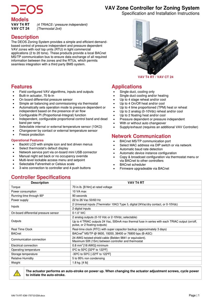
DEOS VAV T4 RT User manual

VAV T4 RT-BACnet Guide-170602.docx
VAV Zone Controller
VAV T4 RT
BACnet Communication Module User Guide
Zoning System

VAV T4 RT VAV Zone Controller
BACnet Communication Module User Guide
www.deos-controls.com
Page | 1
Introduction
The VAV T4 RT VAV Zone Controller BACnet®Communication Module User Guide provides information about using
the controllers in the zoning system with BACnet communications feature. The BACnet communication protocol for
building automation and control networks enables communication between client devices within a network. The
controller provides a BACnet network interface between BACnet client devices and DEOS Controller series devices. It
uses the BACnet Master Slave/Token Passing (MS/TP) protocol at the BACnet MAC layer.
Pre-requisites
The BACnet communication user guide assumes that you are familiar with the concepts of BACnet and its
terminology.
Advantages of BACnet
BACnet enabled controllers have the following advantages:
Quick Message Transmission. The controller uses a synchronous implementation for BACnet messages
making it quick and efficient. Each BACnet confirmed service request is answered as quickly as possible
without using the Reply Postponed frame. The MS/TP implementation is performed within Tusage_delay of
15 minutes to ensure a Tusage_timeout value within 20 minutes.
MS/TP Support. The controller supports a Full Master Node state machine for MS/TP. The Max_Master and
the instances are configured to the device object through BACnet WriteProperty service or via the device's
Programming Mode. The MAC address and the MS/TP baud rate setting of 9600, 19200, 38400, and 76800
are also set through the BACnet Write Property service or via the device's Programming Mode. In
Programming mode, the device is configured through the device’s keypad. For more information about the
WriteProperty, refer to Table 3 - Object Types Supported.
BIBB Support. The controller functions the same way as the B-ASC type profile server and supports the
specific BIBB as per their relevant definitions.
oDS-RP-B
oDS-RPM-B
oDS-WP-B
oDS-WPM-B
oDM-DCC-B
oDM-DDB-B
oDM-DOB-B
oDM-RD-B
oDM-TS-B
oDM-UTC-B
oDS-COV-B
oDS-COVP-B
oSCHED-WS-I-B
Object Support. The controller supports a fixed list of BACnet visible values, which appear as Present_Values
of various BACnet standard object types in addition to a device object. For more information, refer to Table 3 -
Object Types Supported.
Alarms. The controller supports indication of various alarm conditions through value changes in properties of
several objects. However, it does not generate BACnet event notifications.

VAV T4 RT VAV Zone Controller
BACnet Communication Module User Guide
www.deos-controls.com
Page | 2
BACnet Properties Configuration
To establish communication on the network, and guarantee a unique ID of devices in a BACnet system, the following
properties may have to be configured.
Table 1 - BACnet Properties Configuration
Property
Default Value
Configuration
MAC Address
000
Set to a unique address on the network between 000 and 254.
The value can be set manually via the menu.
The value can be set manually through the WriteProperty service to
Device Object.proprietary-property#1000 MSTP-Address.
The values from 128-254 represent MS/TP non-token passing slave
devices.
Device Instance
Auto
The controller automatically configures its device instance to 877,000 +
MAC address.
The value can be set manually via the menu.
The value can be set manually through the WriteProperty service to
Device Object.Object_Identifier.
The device’s Object_Identifier is a combination of the Device
Object_Type (8) and the Device_Instance (0-4194302), therefore its
decimal or hexadecimal representation tends to be incomprehensible.
For example, the Device_Instance=1000 has an equivalent
Object_Identifier of 0x020003E8 hexadecimal or 33555432 decimal.
Baud Rate
0 = Auto
The controller configures its baud rate automatically by detecting the
network upon connection.
The value can be set manually from the available values of (0) Auto, 9600,
19200, 38400, and 76800.
Max_Master
127
Configure Max_Master value to increase network efficiency when there are
less than 127 devices on the network.
The Max_Master value can be changed through the WriteProperty service
to Device Object.Max_Master.
For more information, refer to the MAC Address and Max_Master section.
Device Object.Object_Name
Name of the
device
Configure the name of the device through the WriteProperty service to
Device Object.Object_Name. For example, VAV T4 RT.

VAV T4 RT VAV Zone Controller
BACnet Communication Module User Guide
www.deos-controls.com
Page | 3
Configuration Options
The following Configuration options enable you to configure and run the BACnet features of the controllers quickly.
Quick Setup
Configure the controller for BACnet communication without programming.
1. Ensure that no other device on the network has a MAC address of 0 (the controller's default address).
2. Connect the controller to the network and power it up.
3. The controller automatically configures the baud rate and device instance allowing BACnet Property
Configuration through the Write Property service. See Table 1 - BACnet Properties Configuration.
4. Repeat the steps for each controller.
Manual Setup
Configure the controller for BACnet communication with programming.
1. Access Operation Mode (jumper set to RUN position).
2. Press and hold both function buttons for 5 seconds to access the Quick Access menu.
3. Enter the password, 637.
4. Follow the instructions to configure the MAC Address, MAX Master, Device Instance, and Baud Rate,
manually.
5. Disconnect the power to the controller, connect the controller to the network, and connect the power
again.
MAC Address and Max_Master
The MAC address must be unique on the entire MS/TP network. However, having a unique MAC address and a high
baud rate does not guarantee efficient operation of the controller and other MS/TP units on the MS/TP network. Some
MAC address and Max_Master combinations are more efficient than others. BACnet requires token-passing units to
occasionally “poll” for other masters based on the MAC address and Max_Master.
A poor combination of MAC addresses and Max_Master can lead to a slower network due to lost time polling for
masters that are not present. Unless there are 126 other units on the MS/TP network, the default Max_Master value of
127 is not the most efficient choice for the controller. The Max_Master default value of 127 was selected to ensure
that any master, specifically a BACnet client can be found when the controller is initially started.
Examples of MAC Address and Max_Master Configurations
The following are some of the examples to indicate the optimum combination of Mac address and Max_Master
configurations to ensure a quick and efficient output.
Example 1
MAC=0. Max_Master=127
MAC=1, Max_Master=127
This configuration is slow and inefficient because every time either unit is required to find another master unit, it has to
poll 126 units until it finds the right one to pass the token.
Example 2
MAC=0. Max_Master=5
MAC=1 to MAC=4 are not used
MAC=5, Max_Master=5
This configuration is better than Example 1 but it is still not optimal. The Max_Master is set to the most efficient value
but the gap between the two MAC addresses is high. Therefore, each unit must poll four units until it finds the right
one to pass the token.

VAV T4 RT VAV Zone Controller
BACnet Communication Module User Guide
www.deos-controls.com
Page | 4
Example 3
MAC=0, Max_Master=1
MAC=2, Max_Master=2
This is an incorrect configuration. The MAC=0 will never find MAC=2 because it will never poll for the master MAC
address=2.
Example 4
MAC=0. Max_Master=3
MAC=1, Max_Master=3
MAC=2, Max_Master=3
MAC=3, Max_Master=3
This is an efficient configuration as the units are numbered consecutively and the MAX_Master is set to the most
efficient value. As a general guideline, the most efficient setup for an MS/TP network is one in which the units are
consecutively numbered starting at MAC address 0 and having Max_Master=the maximum MAC address in the
system. If consecutive numbering is not possible, then the next most efficient setup is one in which all units have
Max_Master=the maximum MAC address in the system.
Copy Config
Copy and broadcast the entire configuration of a controller over the network to controllers of the same type using the
Copy Config feature.
1. Access Operation Mode (jumper set to RUN position).
2. Press and hold both function buttons for 5 seconds to access the Quick Access menu.
3. Enter the password, 637.
4. Scroll to Copy Config programming menu and select Yes. Follow the rest of the onscreen instructions.
Note: A Copy Config can also be executed via BACnet. See AV.165, AV.166, AV.167, and BV.90 in Table 6 -
Object Table Information: Analog Value (AV) and Table 9 - Object Table Information: Binary Value (BV) for details.
Network Reset
Reset the controller via BACnet using the Reinitialize Device service. The Reinitialize Device service can be
accessed using the following password: nep.
The Reinitialize Device service has two types of reset such as:
Warm Reset. The Warm Reset restarts the controller with actual configuration.
Cold Reset. The Cold Reset restarts the controller with Factory configuration.
Warning: The Cold Reset erases the actual configuration when setting the MSTP address. Therefore, exercise
caution while performing a Cold Reset.

VAV T4 RT VAV Zone Controller
BACnet Communication Module User Guide
www.deos-controls.com
Page | 5
Device Object Properties
The following table lists all the BACnet properties supported for the device object. The W indicates that the property is
writable using the BACnet WriteProperty service.
Table 2 - Device Object Properties
Property
Value
Writable
Object_Identifier
Programmable where the instance part of the Object_Identifier is in the range of
0-4194302
The device instance must be unique system-wide
The default value for the device instance=877002 (Vendor_Identifier*1000)
W
Object_Name
VAV T4 RT, programmable up to 32 Bytes
W
Description
Programmable up to 32 Bytes (default: BACnet Zone controller)
W
Object_Type
Device
System_Status
Operational
Vendor_Identifier
Always 877
Vendor_Name
Always DEOS Controls
Model_Name
Example, VAVT4RT
Firmware_Revision
currently, 1.2
Application_Software_Version
currently, 2.07
Protocol_Version
Always 1
Protocol_Revision
Always 14
DataBase_Revision
5
Max_APDU_Length_Accepted
Always 480
Segmentation_Supported
(3) = No Segmentation
APDU_Timeout
6,000
W
Number_of_APDU_Retries
Always 3
Local_Time
00:00:00
W
Local_Date
01-Jan-2015 (Thu)
W
UtC_Offset
-300 minutes
W
Daylight_Savings_Status
False
W
Backup_Failure_Timeout
300
W
Configuration_Files
File-1
Last_Restore_Time
2017-04-13 (Thu), 00:00:00:00
Backup_And_Restore_State
IDLE
Backup_Preparation_Time
0
Restore_Completion_Time
0
Restore_Preparation_Time
0
Protocol_Services_Supported
subscribeCOV
atomicReadFile
atomicWriteFile
readProperty
readPropertyMultiple
WriteProperty
writePropertyMultiple
deviceCommunicationControl
reinitializeDevice
unconfirmedPrivateTransfer
timeSynchronization
who-Has
who-Is
utcTimeSynchronization
subscribeCOVProperty
Protocol_Object_Types_Supported
analog-input
analog-output
analog-value
binary-input
binary-output
binary-value
device
file
program
schedule
multi-state-value
Object_List
100
Device_Address_Binding
Always empty
Max_Master
Programmable in the range of 1-127 (default: 127)
W
Max_Info_Frames
Always 1
Active_COV_Subscription
Empty by default. COV subscription will be lost on a power cycle.
Property_List
List of properties that exist within the object.

VAV T4 RT VAV Zone Controller
BACnet Communication Module User Guide
www.deos-controls.com
Page | 6
Property
Value
Writable
Proprietary property #1000
Programmable (default:0)
Represents the MS/TP MAC address in the range of 0 to 254
Values 128 to 254 represent MS/TP non-token passing slave devices
W
Proprietary property #1001
Programmable (default: Auto)
Represents the MS/TP Baud rate (unsigned type)
Values are 0 (Auto), 9600, 19200, 38400, and 76800
Reading this property always returns the actual Baud rate
W
Proprietary property #1002
Programmable (default: 15 minutes)
Represents the period of time that an object in/out of service will automatically
return to normal. Range = 0 to120 minutes (unsigned type)
Writing 0 means no automatic return to normal
W
Proprietary property #1003
0 = Mode ZNB, 1 = Mode VAV
Object Types Supported
The following table lists all the BACnet properties supported for each object type. Most of the properties are locked.
The exception is Present_Value, which represents the dynamic operating values of the device, and the Status_Flag,
Event_State,and Reliability properties, which reflect the availability of the Present_Value. Unless otherwise specified,
properties are not changeable.
Table 3 - Object Types Supported
Object
Type
Enabled
Optional Properties
Supported
Writable Properties
Notes
Note: Writable properties are different for some objects. Refer to the respective Object Table information to know the writable property for objects.
Analog
Input
Reliability
Description
Min_Present_Value
Max_Present_Value
Resolution
COV-Increment
Out_of_Service
COV-Increment
Object will automatically return to Normal after a
programmable period. Refer to Proprietary property
#1002 of Device Object in Table 2 - Device Object
Properties.
Analog
Value
Reliability
Description
COV-Increment
Priority_Array
Relinquish_Default
Present_Value
Out_of_Service
COV-Increment
Refer to Out_of_Service Property section on page
7 for more information.
Object will automatically return to Normal after a
programmable period. Refer to Proprietary
property #1002 of Device Object in Table 2 -
Device Object Properties.
Analog
Output
Description
Reliability
Min-Pres-Value
Max-Pres-Value
Resolution
COV-Increment
Present_Value
COV-Increment
Binary
Input
Reliability
Active_Text
Inactive_Text
Description
Out_of_Service
Object will automatically return to Normal after a
programmable period. Refer to Proprietary property
#1002 of Device Object in Table 2 - Device Object
Properties.
Binary
Value
Reliability
Active_Text
Inactive_Text
Description
Priority_Array
Relinquish_Default
Present_Value
Out_of_Service
Object automatically returns to Normal after a
programmable time. Refer to Proprietary property
#1002 of Device Object in Table 2 - Device Object
Properties.
Binary
Output
Description
Reliability
Inactive-text
Active-text
Present_Value
Device
Max_Master
Max_Info_Frame
Description
active-COV-subscriptions
#1000 (MSTP addr)
#1001 (Baud rate)
#1002 (Time out)
Local_Time
Local_Date
UTC_Offset
Daylight_Savings_Status
Object_Identifier
Object_Name
Max_Master
Description
Local_Time
Local_Date
UTC_Offset
Daylight_Savings_Status
Apdu_Timeout
Backup_Failure_Timeout
#1000

VAV T4 RT VAV Zone Controller
BACnet Communication Module User Guide
www.deos-controls.com
Page | 7
Object
Type
Enabled
Optional Properties
Supported
Writable Properties
Notes
Apdu_Timeout
Backup_Failure_Timeout
Configuration_Files
Last_Restore_Time
Backup_And_Restore_State
Backup_Preparation_Time
Restore_Completion_Time
Restore_Preparation_Time
#1001
#1002
#1003
Multi-
State
Value
Description
Reliability
States_Text
Priority_Array
Relinquish_Default
Present_Value
Some objects are commandable. In such case, the
priority-array and Relinquish Default properties are
available.
Program
Description
Reliability
Program_Change
Only LOAD and RESTART are supported for
Program Change.
Use LOAD to apply the new firmware.
File
Description
Archive
File Size
Only 0 is the accepted value to be written into file
size.
Schedule
Description
Weekly Schedule
Effective Period
Weekly Schedule
Schedule Default
Priority For Writing
Out_of_Service
Out_of_Service Property
DEOS controllers offer the use of the Out_of_Service writable property. When the value of this property is set to True,
it disconnects the object from the physical input, enabling you to input other values. This is useful for special
applications or while troubleshooting. For example, you can ignore the temperature read from a sensor and input the
desired temperature value in order to perform specific tests.
For security reasons, a timeout will set the Out_of_Service property back to False after 15 minutes. This value can be
modified to between 0 and 120 minutes (For more information, see proprietary property #1002 in Table 2 - Device
Object Properties).

VAV T4 RT VAV Zone Controller
BACnet Communication Module User Guide
www.deos-controls.com
Page | 8
Object Table Information
The VAV T4 RT system uses the following BACnet object tables, categorized on the basis of their ID. The type is the BACnet Object type, the instance is the BACnet Object.
Together, the type and instance form the BACnet Object_Identifier for an object according to the following C-language algorithm:
object_identifier=(unsigned long)((unsigned long)type<<22)+instance
Analog Input (AI)
Table 4 - Object Table Information: Analog Input (AI)
ID
Name
List
Description
W?
Notes
AI.2
AI2_AuxIn
Integrator
Auxiliary input. Temperature or percentage 0 to 100% (0 to 100% = 0 to 10
Vdc) or ON/OFF set by MSV.5 Cfg_AI2_Type.
Out_of_Service
COV Increment (0.5)
Temp = -40°F to 212°F or -40°C to 100°C
Resolution 0.2°F/0.1°C
% = 0 Volts to 100 Volts, Resolution 0.1 Volt
On/Off = 0, 1
AI.3
RoomTemperature
Integrator
Room temperature read by the internal sensor.
Out_of_Service
COV Increment (0.1)
32ºF to 122ºF or 0ºC to 50ºC
Resolution 0.02ºF/0.01ºC
Analog Output (AO)
Table 5 - Object Table Information: Analog Output (AO)
ID
Name
List
Description
W?
Notes
AO.1
AnalogOutput1
Integrator
Status value that represents the modulation percentage of analog output 1
based on demand.
Present Value
COV Increment (0.5)
0% to 100%, Resolution 0.1%
AO.2
AnalogOutput2
Integrator
Status value that represents the modulation percentage of analog output 2
based on demand.
Out_of_Service
COV Increment (0.5)
0% to 100%, Resolution 0.1%
Analog Value (AV)
Table 6 - Object Table Information: Analog Value (AV)
ID
Name
List
Description
W?
Notes
AV.3
Local_AI1_SAT_CO
Integrator
Local suply air temperature on analog input 3.
Out_of_Service
COV Increment (0.5)
-40°F to 212°F or -40°C to 100°C
Resolution 0.02ºF/0.01°C
AV.6
OAT
Integrator
Outdoor air temperature from RTC 1010.
COV Increment (0.5)
-40°F to 212°F or -40°C to 100°C
Resolution 0.02ºF/0.01°C
AV.10
Cfg_CalibRoomTemperature
Integrator
Configuration value that represents the calibration of room temperature. Can be
calibrated from the minimum to the maximum temperature.
Present Value
COV Increment
-40°F to 212°F or -40°C to 100°C
Resolution 0.02ºF/0.01°C

VAV T4 RT VAV Zone Controller
BACnet Communication Module User Guide
www.deos-controls.com
Page | 9
ID
Name
List
Description
W?
Notes
AV.15
OccupiedTemperatureSetpoint
Integrator
Configuration value used to set the actual user setpoint of the zone in
occupied/day mode.
Present Value
COV Increment (0.5)
AV.16 to AV.17, Resolution 0.02ºF/0.01°C
AV.16
Cfg_MinSetpoint
Integrator
Configuration value used to set the user minimum permitted setpoint of the
zone in occupied/day mode.
Present Value
COV Increment (0.5)
-40°F to 212°F or -40°C to 100°C (-40°F/-40°C to
AV.17), Resolution 0.02ºF/0.01°C
AV.17
Cfg_MaxSetpoint
Integrator
Configuration value used to set the user maximum permitted setpoint of the
zone in occupied/day mode.
Present Value
COV Increment (0.5)
-40°F to 212°F or -40°C to 100°C (AV.16 to
212°F/100°C), Resolution 0.02ºF/0.01°C
AV.18
UnoccupiedCoolSetpoint
Integrator
Configuration value of the cooling setpoint during no occupancy mode. The
cooling setpoint is restricted by the heating setpoint.
Present Value
COV Increment
50°F to 104°F or 10°C to 40°C (50°F/10°C to
AV.12), Resolution 0.02ºF/0.01°C
AV.19
UnoccupiedHeatSetpoint
Integrator
Configuration value of the heating setpoint during no occupancy mode for
return air temperature. The heating setpoint is restricted by the cooling setpoint.
Com lost RAT control setpoints.
Present Value
COV Increment
50°F to 104°F or 10°C to 40°C (AV.11 to
104°F/40°C), Resolution 0.02ºF/0.01°C
AV.20
HeatingDemand
Integrator
Status value that represents the heating demand in percentage for the Heating
Ramp. The heating demand value is based on zone temperature, zone setpoint
and values set for the actual ramp (AV.21 and AV.22).
Read only
COV Increment (5)
0 to 100%, Resolution 0.5%
AV.21
Cfg_HeatingPropBand
Advanced
Configuration value that represents the range through which the controller will
modulate the heating output from 0 to 100%.
Present Value
COV Increment (0.5)
1ºF to 10ºF or 0.5ºC to 5ºC, Resolution 1ºF/0.5ºC
AV.22
Cfg_HeatingDeadBand
Advanced
Configuration value that represents the range where the controller will not take
action when below the zone setpoint.
Present Value
COV Increment (0.1)
0°F to 10°F or 0°C to 5°C, Resolution 0.2ºF/0.1ºC
AV.23
DuctReheatDemand
Integrator
Status value that represents the reheat demand.
Read only
COV Increment (0.1)
0 to 100%, Resolution 0.1%
AV.24
Cfg_DuctReheatPropBand
Advanced
Configuration value that represents the range through which the controller will
modulate the reheat output from 0 to 100%.
Present Value
COV Increment (0.5)
1ºF to 10ºF or 0.5ºC to 5ºC, Resolution 1ºF/0.5ºC
AV.25
Cfg_DuctReheatDeadBand
Advanced
Configuration value that represents the range at which the controller will not
take action when below the zone setpoint.
Present Value
COV Increment (0.3)
0°F to 10°F or 0°C to 5ºC, Resolution 0.2ºF/0.1ºC
AV.26
PerimeterReheatDemand
Integrator
Status value that represents the perimeter (baseboard) reheat demand.
Read only
COV Increment (5)
0 to 100%, Resolution 0.1%
AV.27
Cfg_PerimeterReheatPropBand
Advanced
Configuration value that represents the range through which the controller will
modulate the perimeter (baseboard) reheat from 0 to 100%.
Present Value
COV Increment (0.5)
1ºF to 10ºF or 0.5ºC to 5ºC, Resolution 1ºF/0.5ºC
AV.28
Cfg_PerimeterReheatDeadBand
Advanced
Configuration value that represents the range at which the controller will not
take action when below the zone setpoint.
Present Value
COV Increment (0.1)
0°F to 10°F or 0°C to 5ºC, Resolution 0.2ºF/0.1ºC
AV.30
Cfg_IntegralTimeHeating
Advanced
Configuration value that represents the reciprocal of the integral time in
seconds (1/I or repeats per second). To obtain a slower reaction time, the value
of the integral must be small. To obtain a quicker reaction, the integral must be
bigger.
Present Value
COV Increment (5)
0 to 250 seconds, Resolution 5 seconds
AV.36
Cfg_HeatingDemandBalance
Integrator
Configuration value that represents the heating demand balance for a zone.
Present Value
COV Increment (0.1)
0 to 100%, Resolution 0.1%
AV.37
HeatingWeightedDemand
Integrator
Heating weighted demand for a zone (value sent to RTC 1010).
COV Increment (0.1)
0 to 100%, Resolution 0.1%
AV.38
Cfg_CoolingDemandBalance
Integrator
Configuration value that represents the cooling demand balance for a zone.
Present Value
COV Increment (0.1)
0 to 100%, Resolution 0.1%
AV.39
CoolingWeightedDemand
Integrator
Cooling weighted demand for a zone (value sent to RTC 1010).
COV Increment (0.1)
0 to 100%, Resolution 0.1%
AV.40
CoolingDemand
Integrator
Status value that represents the cooling demand for the Cooling Ramp. The
cooling demand value is based on zone temperature, zone setpoint and values
Read only
COV Increment (5)
0 to 100%, Resolution 0.5%

VAV T4 RT VAV Zone Controller
BACnet Communication Module User Guide
www.deos-controls.com
Page | 10
ID
Name
List
Description
W?
Notes
set for the actual ramp.
AV.41
Cfg_CoolingPropBand
Advanced
Configuration value that represents the range through which the controller will
modulate the cooling output from 0 to 100%.
Present Value
COV Increment (0.5)
1ºF to 10ºF or 0.5ºC to 5ºC, Resolution 1ºF/0.5ºC
AV.42
Cfg_CoolingDeadBand
Advanced
Configuration value that represents the range at which the controller will not
take action when above the zone setpoint.
Present Value
COV Increment (0.1)
0°F to 10°F or 0°C to 5°, Resolution 0.2ºF/0.1ºC
AV.50
Cfg_IntegralTimeCooling
Advanced
Configuration value that represents the reciprocal of the integral time in
seconds (1/I or repeats per second). To obtain a slower reaction time, the value
of the integral must be small. To obtain a quicker reaction, the integral must be
bigger.
Present Value
COV Increment (5)
0 to 250 seconds, Resolution 5 seconds
AV.58
Cfg_ChangeOverSetpoint
Advanced
Configuration value of the temperature at which the primary air from the central
system is considered to be in cooling or heating. Note that there is a 1.5°C
(2.7°F) dead band on each side of the setpoint.
Present Value
COV Increment (0.5)
50°F to 104°F or 10°C to 40°C,
Resolution 1ºF/0.5ºC
AV.59
Cfg_ChangeOverDelay
Integrator
Configuration value that represents the delay in changeover.
Present Value
COV Increment (1)
0 to 180 minutes, Resolution 15 minutes
AV.61
Cfg_NoOccOverrideDelay
Integrator
Configuration time in minutes when unoccupied and an override has been
activated on the controller.
Present Value
COV Increment (1)
0 to 180 minutes, Resolution 15 minutes
AV.70
Cfg_AnalogOutput1 Min
Advanced
This value represents the minimum control signal of the controlled element. If
the signal is 0 to 10Vdc then the minimum value is 0 Volts and if the signal is 2
to 10 Vdc then minimum value is 2 Volts. This value is the 0 position at 0%
demand. If set at 2 Volts, a 2 Volt is applied continuously even when there is no
demand. It cannot be used to set the minimum starting activation position.
Present Value
COV Increment (0.5)
0 Volt to AV.71, Resolution 0.1 Volt
AV.71
Cfg_AnalogOutput1 Max
Advanced
This value represents the maximum control signal of the controlled element. If
the signal is 0 to 10Vdc or 2 to 10Vdc then the maximum value is 10 Volts. It
can also be used to limit the maximum output of the controller. If the control
signal is 0 to 10Vdc and the maximum voltage value is set to 8 Volts, the
controlled element will never go over 80% of its total capacity.
Present Value
COV Increment (0.5)
AV.70 to 10.0 Volt, Resolution 0.1 Volt
AV.72
Cfg_AnalogOutput2 Min
Advanced
This value represents the minimum control signal of the controlled element. If
the signal is 0 to 10Vdc then the minimum value is 0 Volts and if the signal is 2
to 10 Vdc then minimum value is 2 Volts. This value is the 0 position at 0%
demand. If set at 2 Volts, a 2 Volt is applied continuously even when there is no
demand. It cannot be used to set the minimum starting activation position.
Present Value
COV Increment (0.5)
0 Volt to AV.73, Resolution 0.1 Volt
AV.73
Cfg_AnalogOutput2 Max
Advanced
This value represents the maximum control signal of the controlled element. If
the signal is 0 to 10Vdc or 2 to 10Vdc then the maximum value is 10 Volts. It
can also be used to limit the maximum output of the controller. If the control
signal is 0 to 10Vdc and the maximum voltage value is set to 8 Volts, the
controlled element will never go over 80% of its total capacity.
Present Value
COV Increment (0.5)
AV.72 to 10.0 Volt, Resolution 0.1 Volt
AV.88
Cfg_DamperMaxPositionCool
Integrator
Configuration value that represents the maximum damper position when the
system is in cooling mode and the zone is in 100% cooling demand.
Present Value
COV Increment (1)
AV.90 to 100%, Resolution 1%
AV.89
Cfg_DamperMaxPositionHeat
Integrator
Configuration value that represents the maximum damper position when the
system is in heating mode and the zone is in 100% heating demand.
Present Value
COV Increment (1)
AV.90 to 100%, Resolution 1%
AV.90
Cfg_DamperMinPosition
Integrator
Configuration value that represents the minimum damper position when the
system is in cooling or heating mode (at all times).
Present Value
COV Increment (1)
0% to 100%, Resolution 1%
AV.92
Cfg_DamperMaxPositionReheat
Integrator
Configuration value that represents the maximum damper position when the
system is in cooling mode, but the zone is requesting heat. This configuration is
only available if the zones are equipped with a modulating duct reheat.
Present Value
COV Increment (1)
0% to 100%, Resolution 1%

VAV T4 RT VAV Zone Controller
BACnet Communication Module User Guide
www.deos-controls.com
Page | 11
ID
Name
List
Description
W?
Notes
AV.93
CurrentDamperPosition
Integrator
Value that represents the current position of the damper.
Out of service
COV Increment (1)
0 to 100%, Resolution 1%
AV.101
Cfg_AirFlowKFactor
Integrator
Configuration value that represents the maximum airflow of the VAV box at 1"
W.C.
Present Value
COV Increment (5)
100 to 9,995 units, Resolution 5 units
AV.102
Cfg_AirFlowMin
Integrator
Configuration value used during airflow balancing sequence. Refer to VAV-
Airflow Balance Instructions.
Present Value
COV Increment (1)
0 to 9,995 units, Resolution 1 unit
Writable only if system is in balancing mode
AV.103
Cfg_AirFlowCoolMax
Integrator
Configuration value that represents the maximum cooling airflow when system
is in cooling mode.
Present Value
COV Increment (5)
(12.7%) Kfac to 9,995 units, Resolution 5 units
AV.105
Cfg_AirFlowHeatMax
Integrator
Configuration value that represents the maximum cooling airflow when system
is in heating mode.
Present Value
COV Increment (5)
(12.7%) Kfac to 9,995 units, Resolution 5 units
AV.107
Cfg_AirFlowReHeatMax
Integrator
Maximum reheat airflow for pressure independent system.
Present Value
COV Increment (5)
AV.102 to AV.101, Resolution 1 unit
AV.110
ActualAirFlow
Integrator
Status value that represents the actual converted airflow measured by the
differential pressure transducer.
Out of Service
COV Increment (1)
0 to 9,995 units, Resolution 1 unit
Restricted by AV.103 and AV.105
AV.111
AirFlowSetPoint
Integrator
Status value that represents the airflow calculated by demand.
Out of Service
COV Increment (1)
0 to 9,995 units, Resolution 1 unit
Restricted by AV.103 and AV.105
AV.112
Cfg_AdjustAirFlowMax
Integrator
Configuration value used during airflow balancing sequence.
Refer to VAV-Airflow Balance Instructions.
Present Value
COV Increment (1)
0 to 9,995 No units, Resolution 1 No unit
Writable only if system is in balancing mode
AV.113
Cfg_AdjustAirFlowMin
Integrator
Configuration value used during airflow balancing sequence.
Refer to VAV-Airflow Balance Instructions.
Present Value
COV Increment (1)
0 to 9,995 No units, Resolution 1 No unit
Writable only if system is in balancing mode
AV.114
Cfg_AirFlowOffset
Integrator
Configuration value used to adjust the calibration of the differential pressure
transducer. Refer to VAV Airflow Balance Instructions.
Present Value
COV Increment (1)
-500 to 500 No units, Resolution 1 No unit
AV.133
Cfg_Input3 Reading
Advanced
Status value that represents the voltage output value in mV of the pressure
sensor.
Out of Service
COV Increment (5)
250mV (0") to 4,000mV (1")
AV.150
MSTPBaudRate
Integrator
Status value that indicates the rate at which the Baud rate can be configured on
an MSTP network.
Present Value
(0) Auto, 9600, 19200, 38400, and 76800.
Resolution Auto
AV.151
MSTPAdd
Integrator
Status value that indicates the MAC address of the controllers on an MSTP
network.
Present Value
0 to 254, Resolution 1 unit
AV.152
DeviceInstance
Integrator
Status value that indicates the device identification instance. The instance is
configured as per the Auto Instance Setting.
Present Value
0 to 4194302, Resolution 1 unit
AV.160
Cfg_DuctOATHeatLock
Integrator
Configuration value that represents the use of duct reheat, as required. The
duct reheat value is not dependent on the outdoor air temperature value.
Setting a duct heat lockout setpoint prevents activation of the duct reheat when
outside air temperatures are above the setpoint.
Present Value
COV Increment (0.5)
-15°F to 120°F or -26°C to 50°C
Resolution 0.1°F /0.1°C
AV.161
Cfg_PerimeterOATHeatLock
Integrator
Configuration value that represents the use of perimeter (baseboard) reheat.
The perimeter value is not dependent on the outdoor air temperature value.
Setting a perimeter lockout setpoint prevents activation of the baseboard reheat
when outside air temperatures are above the setpoint.
Present Value
COV Increment (0.5)
-15°F to 120°F or -26°C to 50°C
Resolution 0.1°F /0.1°C
AV.165
CopyCfgStartAddress
Integrator
When using copy config, this value represents the first address in the range of
copied controllers.
Present Value
0 to 254 (AV.165 to 254), Resolution 1 unit
AV.166
CopyCfgEndAddress
Integrator
When using copy config, this value represents the last address in the range of
copied controllers.
Present Value
0 to 254 (AV.165 to AV.166), Resolution 1 unit

VAV T4 RT VAV Zone Controller
BACnet Communication Module User Guide
www.deos-controls.com
Page | 12
ID
Name
List
Description
W?
Notes
AV.167
CopyCfgResult
Integrator
When using copy config, this value is used to verify that the copy to the
controllers was successful or failed.
Present Value
Succeed, Progerr, Typeerr, Modlerr, Memerr,
Slave, Commerr
AV.182
TO1 Pulsing
Integrator
TR Status value to show the pulse signal demand. This value can be
overridden. IAC output 1 when set to Pulsed, indicates the pulse signal
demand.
Present Value
COV Increment (1)
0% to 100%, Resolution 0.1%
AV.185
TO4 Pulsing
Integrator
Status value to show the pulse signal demand. This value can be overridden.
Present Value
COV Increment (1)
0% to 100%, Resolution 0.1%
AV.200
Cfg_MU_MSTP_MacAdd
Integrator
BACnet MSTP address for RTC 1010.
Present Value
0 to 255 units, Resolution 1 unit
Binary Input (BI)
Table 7 - Object Table Information: Binary Input (BI)
ID
Name
List
Description
W?
Notes
BI.1
DigitalInput1
Integrator
Contact status of the input. (0) Open, (1) Close
Out_of_Service
0 = Open, 1 = Close
BI.2
DigitalInput2
Integrator
Contact status of the input. (0) Open, (1) Close
Out_of_Service
0 = Open, 1 = Close
Binary Output (BO)
Table 8 - Object Table Information: Binary Output (BO)
ID
Name
List
Description
W?
Notes
BO.1
BinaryOutput1
Integrator
Status value to show if BO1 is active or not. (0) OFF, (1) ON. This value may
be overridden.
Present Value
0 = Off, 1 = On
BO.2
BinaryOutput2
Integrator
Status value to show if BO2 is active or not. (0) OFF, (1) ON. This value may
be overridden.
Present Value
0 = Off, 1 = On
BO.3
BinaryOutput3
Integrator
Status value to show if BO3 is active or not. (0) OFF, (1) ON. This value may
be overridden.
Present Value
0 = Off, 1 = On
BO.4
BinaryOutput4
Integrator
Status value to show if BO4 is active or not. (0) OFF, (1) ON. This value may
be overridden.
Present Value
0 = Off, 1 = On
Binary Value (BV)
Table 9 - Object Table Information: Binary Value (BV)

VAV T4 RT VAV Zone Controller
BACnet Communication Module User Guide
www.deos-controls.com
Page | 13
ID
Name
List
Description
W?
Notes
BV.1
Cfg_TempUnitBACnet
Integrator
Configuration of the temperature units used in BACnet.
If set to (0), the temperature will be in Celsius scale. If set to (1), the
temperature will be in Fahrenheit scale.
Present Value
0 = Celsius,1 = Fahrenheit
BV.2
Cfg_TempSetPointLock
Integrator
Configuration to lock the zone setpoint and prevent users to change the value.
(0) disable setpoint lock, (1) enable setpoint lock.
Present Value
0 = Disable, 1 = Enable
BV.4
Cfg_TempUnitTstat
Integrator
Configuration of the user temperature units used on TRL. If set to (0), the
temperature will be in Celsius, If set to (1), the temperature will be in
Fahrenheit.
Present Value
0 = Celsius,1 = Fahrenheit
BV.5
LocalChangeOverMode
Integrator
Status value of the actual mode. (0) Cooling, (1) Heating.
Present Value
0 = Cooling, 1 = Heating
BV.32
Cfg BO 1 Direction
Advanced
Configuration value to set the direction of binary output 1 as (0) Direct or (1)
Reverse.
Present Value
0 = Direct, 1 = Reverse
BV.35
Cfg BO 4 Direction
Advanced
Configuration value to set the direction of binary output 4 as (0) Direct or (1)
Reverse.
Present Value
0 = Direct, 1 = Reverse
BV.37
OverrideOccupancy
Integrator
Status to inform if an override is active. (0) No, (1) Yes
Read Only
0 = No, 1 = Yes
BV.40
Cfg_MotorDirection
Integrator
Configuration to change the rotation direction of the damper actuator. When set
to (0) Direct, the damper actuator is configured to open from 0° to 90°. When
set to (1) Reverse the damper actuator is configured to open from 90° to 0°.
When this value is changed, the controller will execute an auto-stroke to reset
the actuator's position.
Present Value
0 = Direct, 1 = Reverse
BV.45
AirFlowBalancing
Integrator
Configuration value to enable and disable the airflow balancing.
Present Value
0 = Disable, 1 = Enable
BV.47
BalancingModeActive
Integrator
Configuration value to enable and disable the balancing mode.
Present Value
0 = Disable, 1 = Enable
BV.50
Cfg_PressureModeSelect
Integrator
Configuration value to configure the VAV box as (0) pressure independent or
(1) pressure dependent.
Present Value
0 = Independent, 1 = Dependent
BV.68
Cfg_ChangeOverType
Integrator
Configuration value that determines if the change over mode is from the RTC
1010 or from the local sensor AV.3 Local AI3 SAT. (0) Master Unit, (1) Locally
Present Value
0 = Master Unit, 1 = Locally
BV.69
MU_ChangeOverMode
Integrator
Change over mode from RTC 1010. (0) Cooling, (1) Heating
Present Value
0 = Cooling, 1 = Heating
BV.90
CopyCfgExecute
Integrator
When using copy config, this value is used to start the copy to other controllers.
(0) No, (1) Yes Note: The BACnet schedule is not copied during a Copy Config
operation.
Present Value
0 = No, 1 = Yes
BV.105
Cfg_NoMinPositionC_Over
Integrator
Configuration value to bypass the minimum position of damper if change over
in opposite mode is required. (0) No, (1) Yes
Present Value
0 = No, 1 = Yes
BV.110
Al_DuctReheatLock
Integrator
Status of local duct reheat lock. (0) No, (1) Yes
Present Value
0 = No, 1 = Yes
BV.111
Al_PerimeterReheatLock
Integrator
Status of local duct perimeter reheat lock. (0) No, (1) Yes
Present Value
0 = No, 1 = Yes

VAV T4 RT VAV Zone Controller
BACnet Communication Module User Guide
www.deos-controls.com
Page | 14
Multi State Value (MSV)
Table 10 - Object Table Information: Multi State Value (MSV)
ID
Name
List
Description
W?
Notes
MSV.5
Cfg_AI2_Type
Integrator
Configuration of Auxiliary input on analog input 2.
Percentage: 0 to 10Vdc input converted to 0 to 100%.
Temperature: 10kΩ temperature sensor
OnOff: Binary Input
Present Value
Percentage
Temperature
OnOff
MSV.11
OccCommand
Integrator
Occupancy status from Master Unit (RTC 1010). OccCommand is
commandable, Relinquish Default will be saved to non-volatile memory
Off: Forces the VAV T4 RT Off. Signal sent via BMS.
Occupancy: Forces the VAV T4 RT to occupied or day mode. Signal sent via
BMS.
NoOccupancy: Forces the VAV T4 RT to unoccupied or night setback mode.
Signal sent via BMS.
Relinquish Default
Off
Occupancy
NoOccupancy
MSV.12
EffectiveOccupancy
Integrator
Status that indicates the actual occupancy mode.
NoOccupancy: Zone is not occupied.
Occupancy: Zone is occupied.
Override: Zone is unoccupied but put back to occupied mode for a maximum
pre-determined time set at AV.61.
Present Value
NoOccupancy
Occupancy
Override
MSV.41
Cfg_AirFlowScale
Integrator
Configuration value of the airflow scale used to get a better resolution when
small airflows are configured.
Scale1: No scale is used.
Scale 10: Airflow is multiplied by 10. This scale is used for low airflows up to
999.
Scale 100: Airflow is multiplied by 100. This scale is used for very low airflows
up to 99.
Present Value
Scale1
Scale10
Scale100
MSV.42
AirFlowBal_Mode
Integrator
Position the damper actuator to preset positions. This object is used when
balancing mode (BV.45) is activated
Closed: The damper actuator moves to a fully closed position. Position used to
calibrate airflow offset (AV.114).
Min Flow: The damper actuator moves to the minimum airflow position of the
actual mode it is in. Position used to calibrate the minimum airflow (AV.113).
Max Flow: The damper actuator moves to the maximum airflow position of the
actual mode it is in (AV.105 in heat or AV.103 in cool). Position used to
calibrate the maximum airflow (AV.112).
Full Open: The damper actuator moves to a fully opened position. Position
used to calibrate the maximum airflow (AV.112).
Present value if BV.45
is set to Enable
.
Closed
Min Flow
Max Flow
Full Open
MSV.50
Cfg_FanPowerBox
Integrator
Select the configuration of the FAN Output (BO4).
No: Fan output is not used.
Series: BO4 is always energized during occupied or override periods. BO4 is
energized with demand during Unocc periods.
Parallel: BO4 is always energized with heating demand during all periods.
Present Value
No
Series
Parallel
MSV.51
Cfg_DuctReheat
Integrator
Select the configuration of duct reheat output (AO1 or BO1, BO2, BO3).
No: Duct reheat is not used.
AnalogOutputDA: Direct Acting analog output is used.
AnalogOutputRA: Reverse Acting analog output is used.
Present Value
No
AnalogOutputDA
AnalogOutputRA
1StageOnOff

VAV T4 RT VAV Zone Controller
BACnet Communication Module User Guide
www.deos-controls.com
Page | 15
ID
Name
List
Description
W?
Notes
1StageOnOff: BO1 stage 1 on off is used.
1StagePulsed: BO1 stage 1 pulsing is used
2StagesOnOff: BO1 and BO2 2 stages on off are used.
3StagesOnOff: BO1, BO2, BO3 3 stages on off are used.
1StagePulsed
2StagesOnOff
3StagesOnOff
MSV.52
Cfg_PerimeterReheat
Integrator
Select the configuration of perimeter reheat output (AO2 or BO4).
No: Duct reheat is not used.
AnalogOutputDA: Direct Acting AO2 is used.
AnalogOutputRA: Reverse Acting AO2 is used.
1StageOnOff: BO4 1 stage on off is used.
1StagePulsed: BO4 1 stage pulsing is used.
Present Value
No
AnalogOutputDA
AnalogOutputRA
1StageOnOff
1StagePulsed
MSV.95
Cfg_DisplayInfo
Advanced
Configuration value of the information displayed on the TRL.
Display Temp Demand: TRL will display the actual temperature and
cooling/heating demand.
Display Setpoint Demand: TRL will display the actual setpoint and
cooling/heating demand.
Display Temp: TRL will display the actual temperature but no demand.
Display Setpoint: TRL will display the actual setpoint but no demand.
Display Off: TRL display will be off (no display).
Present Value
Temp and Demand
Setpoint and Demand
Temp only
Setpoint only
Off
MSV.100
Cfg_ObjectList
Integrator
Configuration value of the object list.
Integrator: Object list restricted to Integrator Object List
Advanced: Object list restricted to Integrator and Advanced Object List
Factory: Complete object list is available.
Present Value
Integrator object list
Advanced object list
Factory object list
MSV.101
Cfg_KeypadLockoutLevels
Integrator
Configurations to limit the user’s access to change setpoints, modes, and
passwords. This is represented in a level format.
Level 0: No lockouts
Level 1: Arrow buttons locked
Level 2: Arrow buttons and mode locked
Level 3: Arrow buttons, mode, and password menu locked
Level 4: Arrow buttons, mode, password menu and program mode locked
Present Value
Level 0
Level 1
Level 2
Level 3
Level 3
Other
ID
Name
List
Description
W?
Notes
PGM.1
ProgramFirmware
Integrator
Program firmware. Set to LOAD to program the file in application memory. The
controller will be reset and the firmware will be LOADED into the memory. Use
only the binary file provided by DEOS.
Program Change
Program Change, only LOAD (1) and RESTART
(4) are supported
FIL.1
FirmwareBinaryFile
Integrator
Firmware binary file. Set to LOAD to program the file in application memory.
The controller will be reset and the firmware will be LOADED into the memory.
Use only the binary file provided by DEOS.
File Size
Archive
File Size is accepted for 0 value only.
Other manuals for VAV T4 RT
1
Table of contents
Other DEOS Controllers manuals
Popular Controllers manuals by other brands
Theralux
Theralux POOL+ MANAGER Installation & setup guide
Regin
Regin RVAZ4-24A instructions

Grant
Grant Grant Solar GS222020X Installation and servicing instructions
Honeywell
Honeywell TBC2800 Series Product handbook
Promation Engineering
Promation Engineering P1 A P Series Field manual
Honeywell
Honeywell Tema-Voyager Multi VMC Series installation manual

Georges Renault
Georges Renault CVIS II Operator's manual
Hanna Instruments
Hanna Instruments BL100 Series instruction manual
PI
PI A-812.21 Series user guide
IBM
IBM ServeRAID M5210 user guide
National Instruments
National Instruments cRIO-9032 Getting started guide
Campbell
Campbell SDM-CD16AC product manual
