Derby TTS 20 User manual

1
D
THESE INSTRUCTIONS SHOULD BE READ CAREFULLY AND RETAINED FOR
FUTURE REFERENCE.
BE SURE TO OBSERVE ALL LABELS AND WARNINGS ON THE APPLIANCE.
Edition:03/21_public
Id_Nr. 911 360 650
Installation and technical manual
Dynamic Storage Heater
AU
TTS 20 TTN 40
TTS 24
TTS 30
TTS 36
TTS 40
TTS 51
TTS 61

Edition:03/21_public
2
Manual Storage Heater
Contents
Safety page 3
General page 5
Design and Construction page 7
Operation page 8
Installation page 10
Room Thermostats page 16
Technical Data page 17
Attention : The storage heater must only be installed by a competent electrician.
Edition:03/21_public
3
Manual Storage Heater
SPECIAL NOTES – Safety
Keep children under 3 years of age away from the
appliance unless constant supervision is provided. - The
appliance can be switched on and off by 3- to 7-year-old
children if they are supervised or have been instructed in the
safe use of the appliance and understand the resulting dangers.
The prerequisite for this is that the appliance has been installed
as described. Children aged 3 to 7 must not insert the plug into
the socket or regulate the appliance. - The appliance can be
used by children aged 8 years and above and persons with
reduced physical, sensory or mental capabilities or lack of
experience and knowledge if they have been given supervision
or instruction concerning use of the appliance in a safe way and
understand the hazards involved. - Children must not play with
the appliance. Cleaning and user maintenance must not be
carried out by children without supervision. - Parts of the
appliance can become very hot and cause burns. Special care
must be taken when children and vulnerable persons are
present. - Do not cover the appliance. - Do not place the
appliance directly under a wall socket

Edition:03/21_public
4
Manual Storage Heater
Before setting up, have the load-bearing capacity and tread resistance of the floor checked by
a specialist. When setting up on deep-pile carpets or similar soft floor coverings, it must be
placed on a base plate (accessory) so that the floor clearance is maintained.
Safety
Due to the surface temperature of the electric heat storage unit, the following safety distances
must be observed:
To walls min. 2 cm
To walls made of combustible material (e.g. wood) min. 2 cm
To a covering above (e.g. stone window sill) min. 3 cm
To a ledge made of combustible material (e.g. wood) min. 10 cm
To objects in front of the air outlet grille on all sides min. 50 cm
Between two or more electric heat devices min. 3 cm
Caution:
Do not cover the appliance!
Do not place objects so that they touch the heater!
In the case of curtains and textiles, make sure that they are not blown on by the hot air
stream. Also, do not place flammable or highly heat-insulating materials such as
newspapers, blankets, laundry, spray cans, etc. on or directly next to the unit. Please make
absolutely sure that the unit is securely attached to the wall.
Electric storage heaters must not be operated in rooms that are at risk of fire or explosion
due to dust, gases or vapours. Such rooms include, for example, the short-term operation of
the storage heater when laying, sanding or sealing floors of any kind. In this case, the unit
must not be charged and must also be covered - especially in the area of the ventilation
grille. When setting up heat storage units in commercial premises, please contact your
responsible employers' liability insurance association.
Caution:
Observe national/ regional installation regulations
Edition:03/21_public
5
Manual Storage Heater
Introduction
We congratulate you on your purchase of your Technotherm storage heater.
Although the Installation and Operation of the heater is very simple, we advise that you read
this booklet carefully as it gives you important information on safety, the installation and
operation, as well as the care of the appliance. Please retain the instructions and pass them
on to future occupants of the heated dwelling.
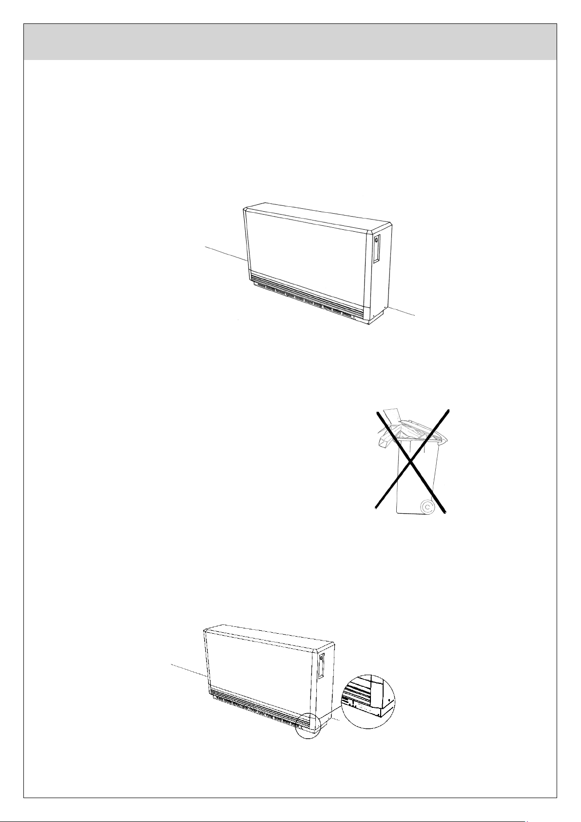
Please note the following: -
dispose of all packing materials in the
proper way.
if the heater shows any sign of damage, report it straight away, before installation!
chipped or slightly damaged bricks can be used without problem.
this heater must only be installed and serviced by a qualified electrician.
Read all the information on the rating label and make sure that this corresponds to the
required values.
Edition:03/21_public
6
Manual Storage Heater
Caution
Storage Heaters may become very hot!
Electric storage heaters are space heating appliances and will attain surface temperatures in
excess of 90°C (195°F) and greater directly in front of or above the discharge grille.
Do not create fire hazards by placing flammable objects, materials or substances on, against
or near the heater.
Keep the air discharge grille clear at all times and allow a 50 cm (19") clearance in front of
the heater, 3cm (1¼“) to the sides and top.
This manual must be read by the installing electrician prior to installation of the heater and by
the owner or occupant prior to operation of the heating system. Save this manual and pass it
on to any new owner or occupant. Should the heater(s) require service, provide this manual
to the service personnel.
This equipment is only for installation in accordance with current Electrical Codes. It should
only be installed by a competent, licensed electrician. Any deviation from these instructions
will result in voiding the warranty and may create a dangerous condition.
Description
How it works...
The concept is simple:
Use electricity when there is little demand for it (usually at night) so that the Electricity
Board can sell it at lower rates.
Turn this cheap electricity into heat which can be easily stored.
Store just enough heat to comfortably meet your daily needs.
Use the stored heat (but not electricity) during the rest of the day when electricity costs
much more because everybody else needs it (industries, businesses, schools and
homes).
Here is how your TTS Heating System does it:
The Electricity Board puts in a different type of electric meter which measures the electricity
you use during the "Off-Peak" hours on one set of dials and the "On-Peak" hours on another
set. Some utilities may, instead, provide a separate meter which measures only the electricity
used by the storage heaters. This will depend on the type of rate your Power Company
offers.
TTS heaters work the same way with any of these rates. When the meter switches at the
pre-set time or by command, from the high rate "On-Peak" to the low rate "Off-Peak", it
signals a control panel in the heating system to turn on the individual TTS heaters and begin
charging them up.
The temperature in each room is controlled independently by a thermostat (integral or wall
mounted) used to operate a small fan within the heater to discharge stored heat as needed.
No other heating system offers the precise combination of thermostat controlled convection
heat supported by a constant background of radiant heat emitted by the warm surfaces of the
heater case. No ups and downs in room temperature, just comfort at its best.
Edition:03/21_public
7
Manual Storage Heater
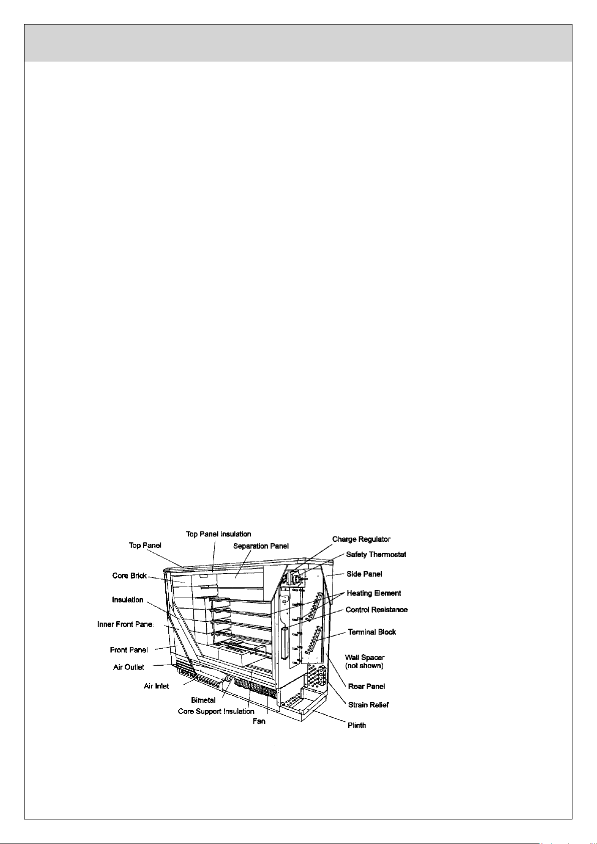
Design and Construction
TTS heaters are an assembly of 6 primary elements:
1. Case - The attractively designed steel case is finished with a high degree of craftsmanship. All
surfaces painted with a neutral off-white baked enamel. This case is very strong and provides the
base upon which all other components are supported.
2. Thermal Insulation - The thermal insulation within the heater provides a key function in the
heaters' design and is a combination of Vermiculite panels and a micro porous type ceramic
material. The result is the ability to store heat within the brick core at temperatures reaching
675°C (1250°F) and yet provide surface temperatures on the case which are typically below 75°C
(165°F).
3. Storage Core - The actual heat storage device is an assembled core made up of refractory
bricks of feolite material, approx. 6 kg (13 lbs) each.
The bricks are identical and are delivered in packs of 2’s and 3’s (see Technical Data, page 14).
The bricks are moulded, high temperature fired and specifically formulated to provide the highest
specific heat and thermal conductivity for the maximum efficiency as a storage core.
4. Heating Elements - The electric heating elements are a metal sheath, rod type made of the
finest materials proven in millions of installations over the past 20 years. This element placed
within the special shaped storage bricks, provides for rapid heat recovery and an even application
of heat to the storage core.
5. Charge Controls - TTS heaters are equipped with two separate thermostat controls, the first is
the "Manual" charge thermostat which can be fitted with a control knob at the front of the heater.
This control is used to manually set the temperature level that the heater storage core will be
charged to during each charge period and thus the amount of heat stored. The second charge
control is a fixed setting "Safety" or high temperature limit thermostat, which will shut the heater
off if the other controls fail to limit the maximum temperatures.
6. Fan Assembly - The TTS heater utilizes a low-volume, slow speed fan to push heat from the
storage core when the wall thermostat signals the need for heat in the room. The fan assembly
also includes the discharge air-mixing valve used to keep the output air temperature at a safe
and comfortable level. TTS heater fans are nearly silent in normal operation and should not cause
concern even in bedroom applications.

Edition:03/21_public
8
Manual Storage Heater
Operating Instructions
The operation of TTS heaters is convenient and economical. The heaters charge overnight.
Radiation from the casing provides a low level of background heat. The fan can be switched
on as desired increasing heat output.
Heater Charging Adjustments
TTS heater charging can be controlled manually.
Manual Control
When only "Manual" adjustment of the TTS heater is needed, the exterior mounted control
knob must be installed. This is the knob that was found in the cardboard shipping support
used between the heater elements. The heater's thermal charge level can now be adjusted
by a simple turn of the knob.
Suggested knob settings for maximum heating comfort and efficiency are:
Summer weather No charge
Cool weather 1/3 charge
Cold weather 2/3 charge
Very cold weather Full charge

Edition:03/21_public
9
Manual Storage Heater
Output Control
A proportion of the stored heat will be radiated from the casing providing a low level of
background heat. Output can be increased by switching on the fan(s) whereby heat is
discharged from the low-level outlet grille.
This is done at the room thermostat located on the control panel. If the thermostat is provided
with an "ON-OFF" switch for the fan(s) set this switch to "ON". Then turn the thermostat knob
to the desired room temperature indicated on the dial. Once set, the thermostat will then
keep the room temperature automatically at this level by switching the fan(s) on and off
accordingly.
Care of the Storage Heater
TTS storage heaters are designed to require minimum maintenance. The surface (when
cool) can be cleaned with any "liquid" household cleaner.
Note - Do not use abrasive cleaners as these may damage the finish.
In those areas where considerable amounts of dust, dirt and/or fur are encountered, it is
recommended that the area behind and in front of the heater be vacuumed quite frequently.
The fan assembly and base compartment should be completely cleaned at least every three
years just before a heating season.
Electrical Shock Hazard
Technotherm storage heaters are supplied by more than one electrical circuit.
Be sure that all circuits are turned off before opening the heater case.
Service should only be made by competent, qualified personnel.

Edition:03/21_public
10
Manual Storage Heater
Installation
Positioning
Please read the instructions in the introductory section concerning position, safety and load-
bearing capacity.
If in doubt, consult a building engineer.
Transport
To facilitate transport, the heater and the bricks are packaged separately. The 7 bricks per
core column are packed in two’s and three’s.
The heating elements are factory fitted and pre-wired.
Preparation
In order to avoid unnecessary scratching
or other damage to the heater it is advised
to unpack it close to its proposed place of
installation.
Tip the carton on its back and remove the
screws from the wooden palette to which
the base of the heater is attached.
Bring the carton back upright, cut the
bands and pull the carton from the heater.
Remove the wooden battens and the
plastic covering and the take the heater
from its palette.
The installation can now begin:
Unscrew the two screws holding the right-hand side panel and, after pulling off the regulator
knob, pull the panel outwards and downwards to remove.
Edition:03/21_public
11
Manual Storage Heater
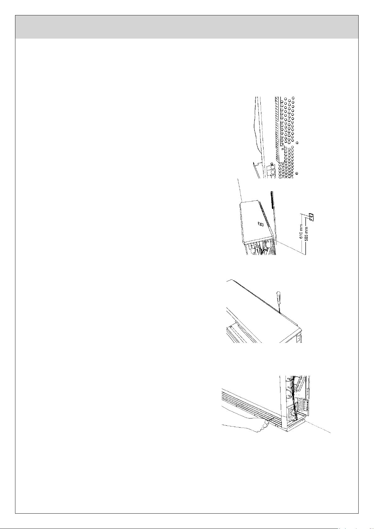
The heater must be prevented from tipping
over by fixing the two brackets to the wall
using the screws and plugs, all of which
are contained in the plastic bag in the
right-hand side of the heater cabinet. If
these screws and plugs are unfit for the
wall fabric in question, other suitable
materials must be used.
The connecting cables can now be drawn
through the strain relief at the back of the
heater and cut to length. Fix the safety
brackets to the wall at the height shown in
the diagram. Remember, when placing the
heater on thick-pile carpeting that the
heater will sink somewhat into the pile.
This must be allowed for as well as if the
heater is placed on a board or feet to raise
it from the carpet. The distance between
the brackets should be about one-half of
the heater length, although the exact
spacing is not important.
For more stability the brackets can be
screwed to the heater through the spacer
bracket at the rear of the heater.
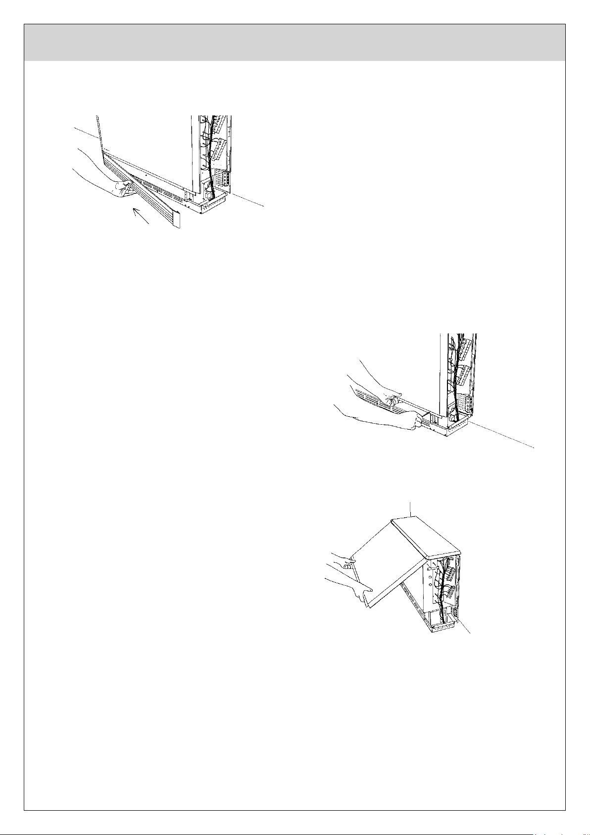
Remove the metric screw at the right-hand
end of the air-outlet grille....
Edition:03/21_public
12
Manual Storage Heater
.... pull the grille slightly outwards and
push it to the left to remove it.
Remove the front panel screws.
Pull the bottom of the front panel out to
about 45° and then pull it downwards to
remove it from the top panel.
Edition:03/21_public
13
Manual Storage Heater
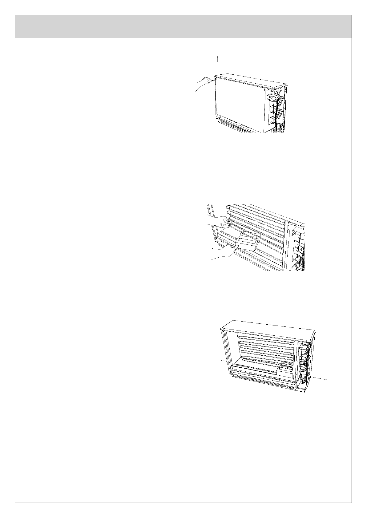
Remove the four screws from the inner
front panel and carefully remove the
panel itself. Be very careful not to damage
the fragile insulation attached to the rear of
the panel.
Having removed the card holding the
heating elements in position, the core
bricks are then put into the heater, starting
with the bottom row. To facilitate this, lift
the heating element up slightly.
The first brick is put into the core on the
left-hand side ...
... then slid across to the right.
Edition:03/21_public
14
Manual Storage Heater
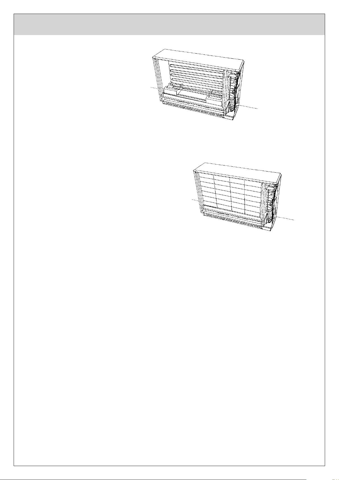
The second brick is then set on the
far left of the core and the remaining
bricks in the middle.
This is repeated until all the bricks have
been installed.
After removing any waste, dust or other particles from the interior of the heater, the panels
can be refitted in the reverse order, i.e.
1. inside front panel
2. outside front panel
3. air-outlet grille.

Edition:03/21_public
15
Manual Storage Heater
Connection of Supply Cables
Warning! THIS APPLIANCE MUST BE EARTHED!
Only heat resisting cable shall be used. The wire in the mains cable will be coloured
according to the following code:
Colours may vary nationally
Green and Yellow: Earth
Brown: Live
Blue: Neutral
The electrical wiring requires two supply cables. Ensure the cable is appropriate for the
heater rating.
1. Feed the two supply cables (three if automatic charge control is used) in from the rear of
the heater through the cable clamp and to the terminal block.
2. Storage Element Supply - Connect the live phase cables to the terminals marked L1, L2
and L3 and connect the neutral to one of the terminals marked N. See instructions on
Page 19 for 240V Connection.
3. Fan Supply - This supply is connected into the terminal strip located below the element
terminal block. Connect the live supply to the terminal marked LE and the neutral supply
to the terminal marked N.
4. Earth Connection - Ensure the earth cables are securely fixed to the earthen screws
located at the bottom of both terminal blocks.
5. Ensure all cables are firmly connected to the terminal blocks.

Edition:03/21_public
16
Manual Storage Heater
System Start-up
Note: All breakers must be off for the heater to be safely de-energized to permit safe
servicing.
Steps to activate the system
1. Control Panel - Energize control panel at the circuit breaker.
2. Fans and Thermostats - Check proper operation of fans and thermostats. Check to see
that the fans go ON and OFF with operation of the thermostat.
3. Circuit Breakers - Switch "ON" all element feed circuit breakers.
4. First Charge - The heater insulation is free from organic binding material. It can thus be
operated immediately without having to go on full charge in order to purge any odours. It
is, however, advisable, to ventilate the room well during the initial charging phase.
5. Current Draw - It is wise to check the current draw of each heater. See the Technical
Data Sheet for the proper amperage. This can be done at the breaker panel or at the
individual heaters.
Edition:03/21_public
17
Manual Storage Heater
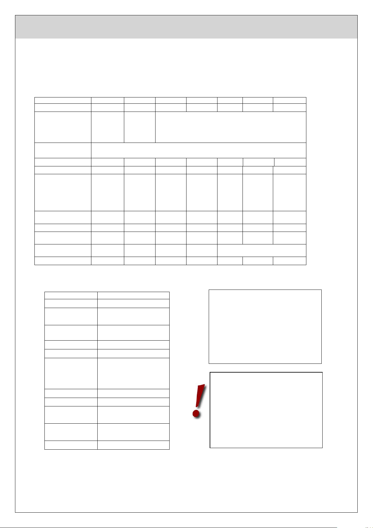
Explanation:
Model TTS 20 – TTS 61 – Device with manual control
Technical Data:
model standard
Model
TTS 20
TTS 24
TTS 30
TTS 36
TTS 40
TTS 51
TTS 61
Nominal rating *
2000 W
2400 W
2700 W
3600 W
4000 W
5000 W
6000 W
Nominal voltage
240 V~
415V 2N~
415V 3N~
50 Hz
240 V~
415V 2N~
415V 3N~
50 Hz
240 V~
415 V 3N~ 50 Hz
Nominal charge
period*
8 h
Nominal charge
16 kW
19,2 kW
24,0 kW
32 kWh
40 kWh
48 kWh
Maximum charge
22 kWh
22 kWh
32 kWh
32 kWh
35 kWh
44 kWh
53 kWh
Dimensions (mm)
width
height
deep
580
660
245
580
660
245
760
660
245
760
660
245
940
660
245
940
660
245
1120
660
245
Weight total
128 kg
32 kg
128 kg
32 kg
183 kg
39kg
183 kg
39 kg
238 kg
238 kg
292 kg
Weight cabinet
32 kg
32 kg
39 kg
39 kg
46 kg
46 kg
53 kg
No. Brick packs
4 x 42
2 x 43
4 x 42
2 x 43
6 x 42
3 x 43
6 x 42
3 x 43
8 x 42
4 x 43
8 x 42
4 x 43
10 x 42
5 x 43
Fan
240 V~ / 50
Hz / 1 x 9 W
240 V~ / 50
Hz / 1 x 9 W
240 V~ / 50
Hz / 2 x 9 W
240 V~ / 50
Hz / 2 x 9 W
240 V~ / 50 Hz / 2 x 9 W
Power ZH**
750 W
750 W
1000 W
1000 W
1000 W
1000 W
1500 W
Technical data:model low
Model
TTN 40
Nominal rating *
4000 W
Nominal voltage
240 V
~
415 V 3N~ 50 Hz
Nominal charge
period*
8 h
Nominal charge
32 kWh
Maximum charge
35 kWh
Dimensions (mm)
width
height
deep
1120 / 1300
536 / 536
245 / 185
Weight total
215 kg
Weight cabinet
43,5 kg
No. Brick packs
5 x 42 / 6 x 44
5 x 43 / 6 x 45
Fan
240 V
~
/ 50 Hz / 2 x 9
W
Power ZH**
1500 W
These heaters are drip-water proof
if mounted to a wall as described in
the installation instructions
*Power ratings with full rated power
** ZH not for Australia
Caution:
An all-pole disconnecting device
must be provided in the dispatcher
system

Edition:03/21_public
18
Manual Storage Heater
Factory-fitted components
TR Charge control
TB Safety thermostat
RS Control resistor
R1..6 Heating elements
IRT 24 Z Integral Room Thermostat
V1.V2 Fans (TT20&30 only one)
PE grounding
Accessories
K1 Thermal Relay
TBZ Safety thermostat for DAE
RZ Day Acting Element (DAE)
SE Fan switch
SZ DAE switct
Terminals
L1,L2,L3 Charge Voltage
A1/Z1 from central
A2/Z2 charge control
LH DAE
LE discharge fan(s)
SH Thermal Relay
L line voltage for IRT
Our equipment is
supplied with power
stickers. Depending on
the connected power,
the corresponding
sticker has to be glued
into the surrounding
area of the rating plate.

19 Edition:03/21_public
Manual Storage Heater Technotherm
Factory-fitted components
TR Charge control
TB Safety thermostat
RS Control resistor
R1..6 Heating elements
V1.V2 Fans (TT20&30 only one)
IRT 24 Z Integral Room Thermostat
PE grounding
Accessories
K1 Thermal Relay
TBZ Safety thermostat for DAE
RZ Day Acting Element (DAE)
SE Fan switch
SZ DAE switct
Terminals
L1,L2,L3 Charge Voltage
A1/Z1 from central
A2/Z2 charge control
LH DAE
LE discharge fan(s)
SH Thermal Relay
L line voltage for IR
Important! Do NOT connect Terminal 13, 14 and 15 to
power supply. Terminal 14 only when an external
Thermostat (accessory) is being use.
All power cables must be disconnected before accessing
the connection terminals.

20 Edition:03/21_public
Manual Storage Heater Technotherm
Additional Information
Operation without auxiliary heating
Switch on the switch.
Turn the integrated room temperature control knob to the maximum position (clockwise stop)
until the room temperature has reached a comfortable level. Then turn the controller knob
slowly to the left until the controller switches off (audible "click"). The room temperature is
now automatically kept constant at this level and needs no further adjustment.
Operation with auxiliary heating (not for Australia)
If the unit is to be operated with auxiliary heating, the switch for the auxiliary heating must be
set to position "I" and the switch for the fan must be set to position.
If heat is still required after the unit has been unloaded, the auxiliary heating switches on
automatically and continues to heat the room. The operation of the auxiliary heating is
indicated by the control lamp. If the room is not to be heated, the room thermostat is switched
off via the fan switch. The setting on the room temperature controller is left as it is.
Energy-saving tip
A higher electricity price usually has to be paid for operation with supplementary heating.
The auxiliary heating should therefore only be switched on when needed. Pay attention to the
position of the switch "I - 0", as the control lamp only lights up during heating operation. At
night, during prolonged ventilation and when the rooms are not in use, we recommend
switching off the discharge fans. This can be done advantageously by installing a central switch
or via a time switch. The setting on the units can then be left as it is. We reserve the right to
make technical changes.
Always interrupt all electrical circuits before undertaking any work in the electrical
compartment.
HEAD OFFICE
Phone (02) 9605 5119 (02) 9618 3842
9/3 Lancaster St Ingleburn NSW 2565 P.O. Box 568 Ingleburn NSW 1890 E:
sales@derbyproducts.com.au W: www.derby-heatbanks.com.au
NSW/ACT/QLD/VIC
D.R. Distribution
9/3 Lancaster St
Ingleburn NSW 2565
Ph: (02) 9605 5119
E: tammy@drdistribution.com.au
TAS
Electrical Agencies
4 Linear Court
Derwent Park TAS 7009
Ph: 03 6273 1855
SA/WA
Derby Heatbanks
P.O. Box 901
Blackwood SA 5051
Ph: 0419 804 946
E: info@derbyheatbanks.com.au
This manual suits for next models
7


