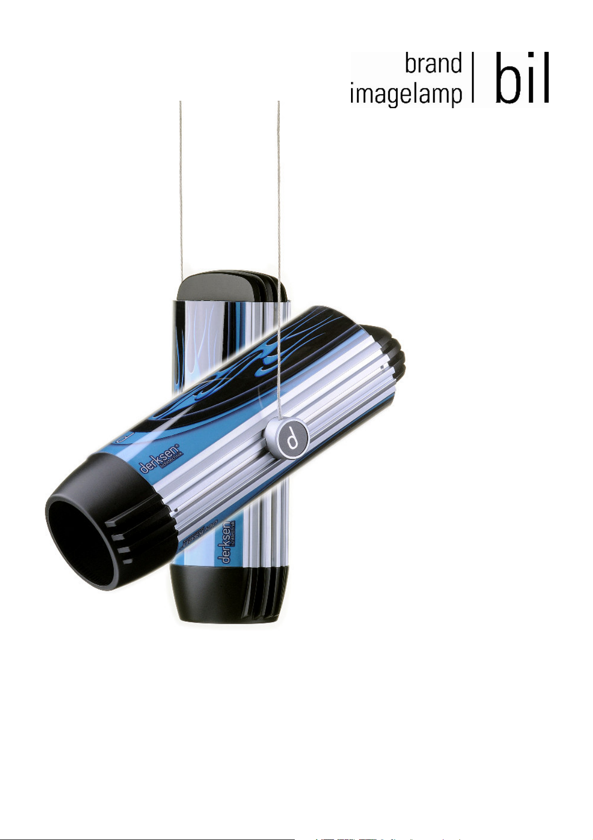
Derksen bil User manual
Reference Manual 115V
- 2 -
Illustration 1

- 3 -
We would like to thank you for deciding to purchase this high quality product.
BIL is solely manufactured in Germany and complies to the highest quality and security standards.
We wish you both successful projections and fascinating moments with your new halogen projection
lamp! In order to get the best effect and safe use of this equipment, please read the user reference
manual prior to use!
Content:
- Projection Lamp BIL including lighting elements/bulbs MR16, 12V/50W, 24°
- 40 mm standard lenses
- Transformer, to be mounted to the ceiling, 11,8V, 20-80 VA (max. 6,5 A)
- Mounting set, containing 2 screws (4 x 30 mm) and 2 universal rawlplugs
Optional accessories available separately:
- Lighting elements/bulb MR16, 12V/50W, 24°
- Telephoto lens with a 85 mm focal distance
- Advertising foil sides for the lampshades
- Gobo-projection patterns with customer-specific motives
You will find further information at www.gobo.de
For more information please visit our homepage at:
www.brandimagelamp.de
Health warning
Warning notes are given to bring to your attention potential risks to both your and others health.
Please read and take note of these health warnings, in order to
ensure safe use of this equipment.
Directions for use
The directions on use are designed to help you to operate this equipment effectively, and avoid
damage through improper use.
Numbering
The figures (1) in the text indicate the appropriate illustration.
W
i

- 4 -
Table of content
Tips for an effective use ........................................................................................................ 5
Surrounding light ...................................................................................................................... 5
Material and colour of the projection surface ........................................................................... 5
Distance between BIL and the projection surface ................................................................... 6
Mounting.................................................................................................................................. 7
Considerations before mounting............................................................................................... 7
Mounting the transformer to the ceiling .................................................................................... 8
Positioning the suspending ropes at the required length ......................................................... 9
Setup and use ....................................................................................................................... 10
Adjusting the lamp .................................................................................................................. 10
Inserting the deflection mirror ................................................................................................. 10
Focusing the projection and adjusting the image ................................................................... 11
Changing the Gobo – Projection Motif ................................................................................... 12
Changing the advertising or tinted foil slides.......................................................................... 13
Replacing the lighting element ........................................................................................... 14
Safety ..................................................................................................................................... 15
Safe environment, conditions of use ...................................................................................... 15
Safety precautions for electricity installations......................................................................... 15
Safety precautions for setup and use ..................................................................................... 16
Transport, cleaning, repairs ................................................................................................ 16
Technical data....................................................................................................................... 17
Terms of guarantee .............................................................................................................. 18
Service address .................................................................................................................... 18
Personal notes ...................................................................................................................... 19
- 5 -
Tips for an effective use
Surrounding light
An optimal result with the best contrast can be achieved in dark or dimmed surroundings. Daylight or
direct sunlight are many times lighter then artificial lighting and will therefore leave the projection
colour faded. Within rooms the result can be improved by avoiding to point spotlights or radiators on
to the projection area.
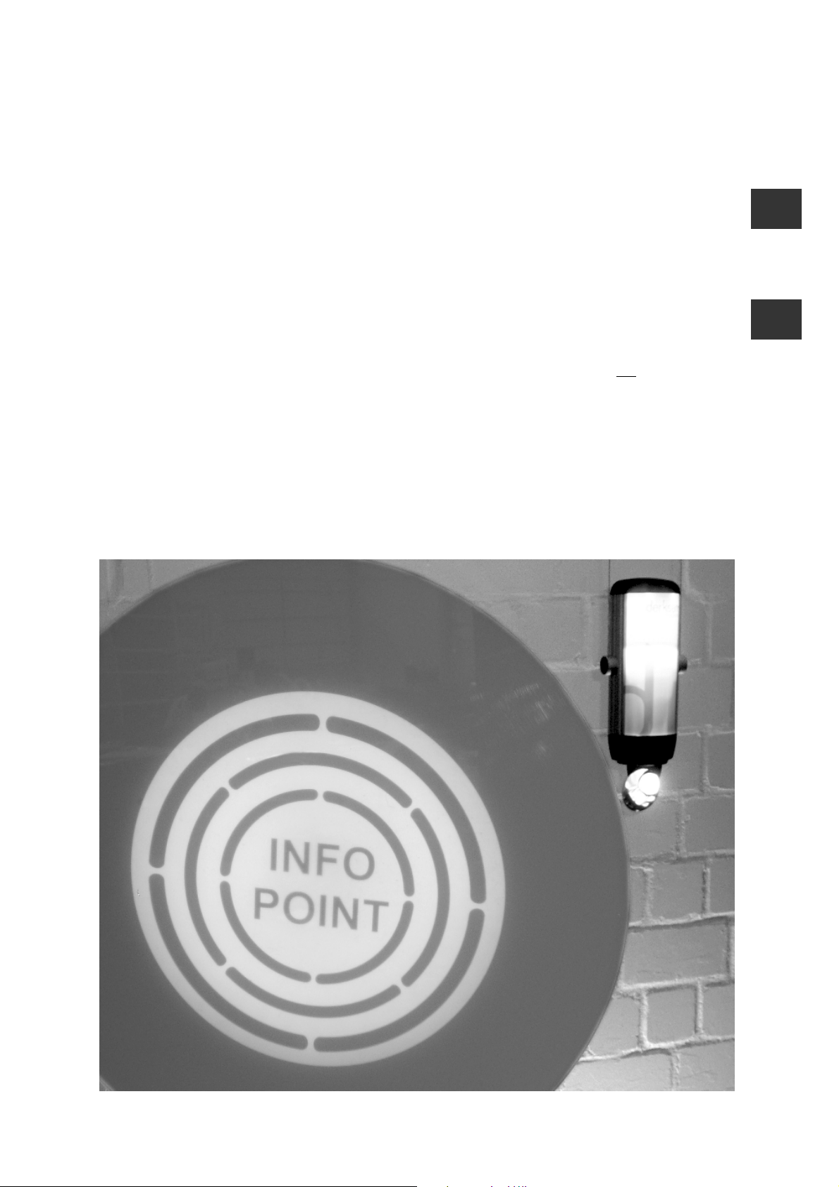
Material and colour of the projection area
The projection lamp BIL allows for projections on to a surface as well as through transparent surfaces.
The image quality greatly depends on the properties of the projection area. Therefore areas to be
projected on need to be non-transparent and should be light in colour. Best results will be gained on
matt white walls or flooring. Articles on display, parts of the decoration or furniture can be used as a
projection surface. However, mirrors, mirrored and or reflective metal surfaces are not suitable for this
purpose. Coloured surfaces will have an influence on the colours being projected.
In order to project through a surface (also called ‘rear projections’) all half-transparent materials, e. g.
calendered glass, frosted glass, transparent materials or paper can make suitable surfaces. For a rear
projection, the BIL is positioned behind the projection area (see Fig. 2). The projected motif is then
visible at both the front and rear side of the area.
Fig. 2: Rear projection – example
Opal glass
i
i
- 6 -
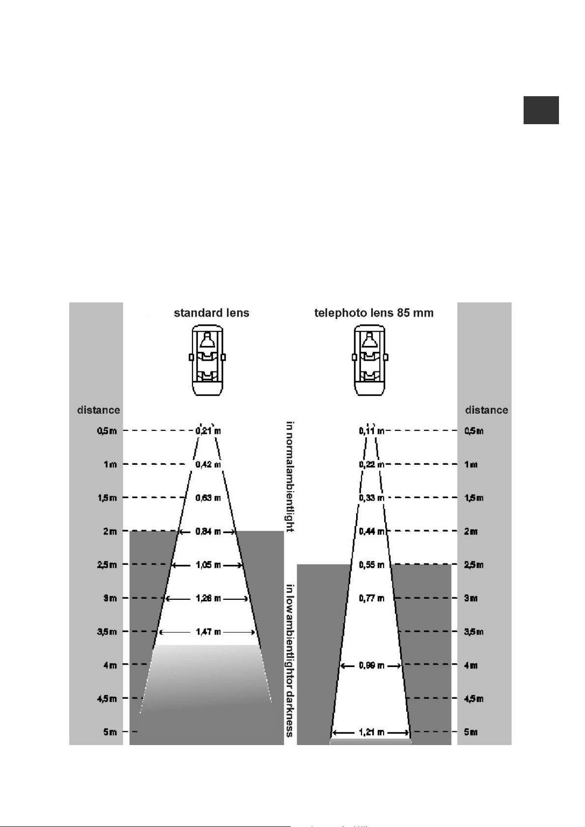
Distance between BIL and the projection surface
As a general rule, an increase in the distance between the projector and the projection surface
increases the size of the projection, whereas both contrast and lightness will decrease. Under normal
room-light conditions, BIL is suitable for projections at a close-up range, i.e. 0.5 to 3.5 mtrs.
In darkness, greater distances are possible. The size of the projection can be influenced by the
distance to the projection surface. Therefore we recommend you to test the projection size prior to
mounting the projection lamp. The built-in standard lens with its 40 mm focal distance can be
exchanged by a telephoto lens with a 85 mm focal distance, in order to customise projection sizes
and distance. The 85 mm telephoto lens is available as an optional accessory. For further information
on this, please contact our customer support service.
Fig. 3: Range and size of the projection depending on the distance between projector and
projection surface
i

- 7 -
Mounting
Considerations before mounting
1. The mounting should be done by a qualified specialist.
2. Take particular care that cabling is given enough slack!
3. Use appropriate fixings that are suitable for the intended mounting area! The enclosed screws
and universal rawlplugs are suitable for fixing the transformer securely to solid ceilings and are
not suitable for use with other construction materials.
4. The transformer housing is designed to take pan head screws of 4 – 5 mm in diameter
(supplied in delivery). Do not use counter sunk screws, as you could damage the housing.
5. Prior to mounting, check whether the location is suitable for projection, and if the distance to the
projection area allows for the intended result. You will find details to help you find the right choice
of location in the previous chapter „Tips for an effective use“.
6. The projection lamp may be set up in a vertical/ horizontal position, or at an angel. The deflection
mirror redirects the projection at an angel of 90° and can be rotated by 360°. By using the
deflection mirror, a lamp that has been mounted vertically can still project in horizontal direction,
e.g. on to a wall (please see the chapter ‚Setup and use’).
7. The maximum permitted length for the suspending ropes is 2 metres. The ropes that are included
in the delivery must not be replaced by longer ones.
8. Never cut the suspending ropes. The ropes’ length can easily be adjusted by merely pulling them
backwards and winding them up inside the transformer casing (see Fig. 6 and 7).
9. Connecting, crossing or putting knots between the left and right suspending rope may lead to a
short circuit (shutdown). This will not damage the device, but lead to a shutdown of the projection
lamp. Therefore, please make sure that the suspending ropes are carefully installed and
unconnected.
10. Avoid sharply bending or twisting the suspending rope, as both may not be reversible later.
W
W

- 8 -
Mounting the transformer on the ceiling
1. Unroll the suspending cables and put them on the ground flat and parallel.
2. Remove the cover plate from the transformer housing by lifting it with little force (please see Fig.
4). The lid is held in place by four barbed hooks. Slide the lid over the suspending ropes until it
rests on the projection lamp.
3. Lay down the projection lamp on a table or ladder underneath the mounting position, so that you
can reach the ceiling without having to lift the projection lamp. You may need a second person to
support you if the ceiling is very high.
4. Hold the transformer housing to the ceiling and mark the positions for the two screws. Make sure
that the connecting wire enters the housing through the intended opening (see Fig. 5).
5. Put the transformer housing to the side and install the drill holes and rawlplugs at the ceiling.
6. Screw the transformer housing to the ceiling. Check that it is mounted safely and tightly.
7. Connect the wires free of stress to the double luster terminal at the transformer housing.
8. Attach the luster terminal to the provided retaining clip (see Fig. 5, magnification underneath).
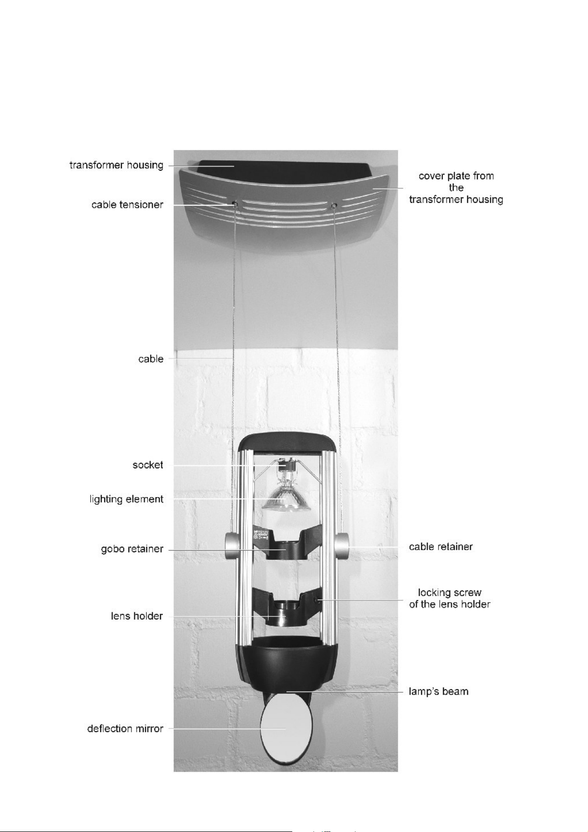
Fig. 4: Opening the transformer housing
Fig. 5: Interior view on the transformer housing

- 9 -
Positioning the suspending ropes at the required length
1. One after the other, the left and right suspending ropes need to be adjusted at the same length (in
small steps, one by one). Make sure that the ropes are not sharpely bent or clamped.
2. Push the cable tensioner upwards „1“ (see Fig. 7 – bottom) and pull the suspension rope through
the tensioner as far as necessary. Upon releasing the cable tensioner, the suspension rope will
automatically be fixed. At this stage, the rope must not be coiled up inside the rope chamber.
3. Wind up any excess rope around two fingers (see Fig. 6) and put the coiled up rope into
the cable chamber next to the cable tensioner.
4. Repeat this procedure with the second suspension rope. Minor length difference of 10 to 40 mm
may be corrected after the transformer housing has been closed.
5. As soon as the suspending ropes have been adjusted to their appropriate length, put the lid on
the transformer housing and make sure it clicks on properly on both sides.
6. Correct any rope length differences by pushing the cable tensioner upwards and sliding the
suspending rope into or out of the transformer housing (see Fig. 7).
Fig. 6: Winding up the cables Fig. 7: Opening the cable tensioner
close open
i

- 10 -
Setup and use
Switch on the projection lamp when the transformer housing has been closed and the lighting element
has been inserted. The projection can only be adjusted with the lamp switched on. Do not touch the
lighting element when the lamp is switched on, as it becomes very hot.
Adjusting the lamp
The projection lamp may be set up in a vertical/ horizontal position, or at an angel. When adjusting the
lamp, it needs to be synchronised with the room’s design and illumination concept. In order to change
the angle of the dismounted projection lamp, turn both cable retainers into the desired position (see
Fig. 8).
Fig . 8: Adjusting the lamp
Inserting the deflection mirror
The deflection mirror redirects the projection at an angle of 90° and can be rotated by 360°. By using
the deflection mirror, a lamp that has been mounted vertically can project in the horizontal direction,
e.g. on to a wall.
1. Set the mirror’s retainer ring in front of the projection lamp’s beam at an angle.
2. Push the retainer ring downwards, until it clicks in firmly.
3. Turn the deflection mirror around the lamp’s longitudinal axis, until the projection appears at the
right spot.
Fig. 9: Inserting the deflection mirror
1 2 3
W

- 11 -
Focusing the projection and adjusting the image
1. Remove the lampshade on the side which holds the screw securing the lens holder. Carefully
slide the lampshade out of its housing and put it to the side.
2. Losen the screw on the lens holder, until it can be moved within the housing together with the lens
(see Fig. 10a).
3. Switch on the projection light and screw the lens in the correct position, until the projected motif
forms a sharp picture (see Fig. 10b).
4. Then tighten the screw, until the lens holder cannot be moved in the housing any more (see Fig.
10a).
Note: Turn the projection motif (Gobo) immediately after switching on the lamp, as by then
the lamp has not yet heated up the projection motif (Gobo) too much.
5. Turn the Gobo – Projection Motif inside the Gobo retainer, until the projected motif has been
correctly adjusted. In order to do that, touch the Gobo with your finger from underneath and turn it
into the desired position. In case your are having difficulties turning the Gobo, gently push up with
your finger to release it. Do not reach into the Gobo retainer from the top, as you may accidentally
touch the hot lighting element.
6. Carefully slide the lampshade back into its housing (see Fig. 13).
Fig. 10: Focusing
a b

- 12 -
Changing the Gobo – Projection Motif
1. Switch off the projection light. Wait and allow the area to cool down.
2. Remove the lampshade from one side. Carefully slide the lampshade out of the housing and lay it
to one side.
3. From underneath, push the Gobo – Projection Motif from the Gobo retainer with your finger. Take
the Gobo, together with the spring ring, carefully out of the Gobo retainer from the top. The black
spacer needs to remain inside the Gobo retainer.
4. Put the new Gobo into the Gobo retainer with its layer or filter side up (see Fig. 11a). Metal Gobos
do not have a layer or filter side and can be inserted any way round. If the motif is meant to be
projected mirror-inverted, the Gobo needs to be inserted the other way round.
5. Put the spring ring inside the Gobo retainer, so that the Gobo cannot fall out (see Fig. 11b).
6. Make sure that the Gobo has not tilted inside the Gobo retainer (irregularly focused projection)
(see Fig. 11c).
7. Switch on the projector light, adjust the projected motif and optimise the focus as necessary (see
page 11).
8. Carefully slide the lampshade back into the housing. (see Fig. 13).
Fig. 11: Changing the motif
a b
c

- 13 -
Changing the advertising or tinted foil slides
BIL is equipped with 2 transparent lampshades that can be fitted with advertising or tinted foil slides.
The lampshade colour can be altered by a slide-in tinted foil slide. Tinted foil slides are available in
various standard colours and can also be custom-made according to the customers wishes.
Additionally, advertising foil slides can be ordered, e.g. for advertising messages, designs, art or other
information. For further information please contact our customer service (see page 18).
1. Carefully slide both lampshades up (towards the rear) and out of the projector lamps’ housing.
2. Place the advertising or tinted foil slide into the lampshades (see Fig. 12).
3. Carefully slide the new lampshades into the profile from the top, until the lamp is closed again
(see Fig. 13).
Fig. 12: Changing the advertising foil slides
Fig. 13: Inserting the lampshades

- 14 -
Replacing the lighting elements
Take care not to come into contact with the hot lighting element and bulb fittings while the equipment
is in operation. Before you replace the lighting element, switch off the equipment and wait for about 15
minutes for it to cool down.
Only use replacement multi-mirror bulbs that have been tested and approved by Derksen Lichttechnik
GmbH. Should the BIL be fitted with an unsuitable bulb, the equipment can become damaged or the
motive will be projected in poor quality.
Approved and tested lighting elements:
- PHILIPS Brilliant Line Pro 12V, 50W, 24°
- BLV Eurostar 12V, 50W, 24°
- OSRAM Dekostar Titan 12V, 50W, 24°
- Sylvania Superia 12V, 50W, 24°
Important: The lighting element must have a reflected beam angle of 24°!
1. Switch off the projection light. Wait until the lighting element has cooled down.
2. Remove the lampshade on one side. Carefully slide the lampshade out of its profile and put it to
the side.
3. Remove the old lighting element from the socket by slightly tilting it and carefully sliding it out of
its socket. Make sure not to bend the 2 retaining clips too much. There is enough space between
the Gobo retainer and the socket to change the lighting element without altering the Gobo
retainer’s position.
4. Carefully set the new lighting element in its socket in the same way (see Fig. 14).
5. Carefully slide the lampshade back into its profile (see Fig. 13).
Fig. 14: Inserting or changing the lighting element
W
- 15 -
Safety
Safe environment, conditions of use
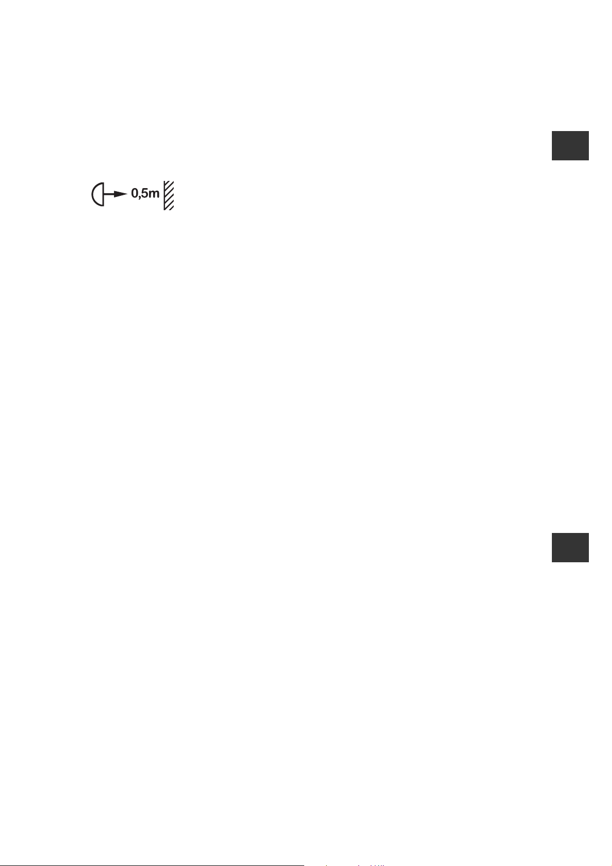
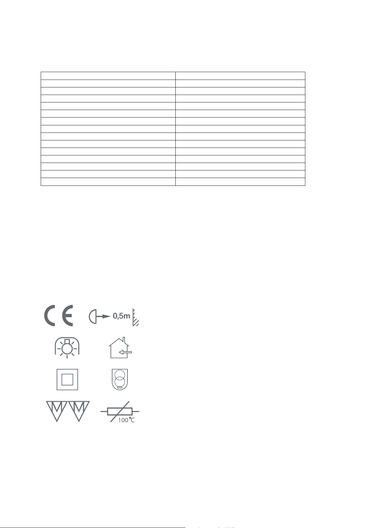
- The device may only be used in closed, dry rooms.
- Please note that the projector’s lens must have a minimum distance of 0.5 mtrs to all flammable
materials and surfaces.
- Both lighting elements and sockets may during their operation reach temperatures of above
100°C. Please allow for the device to cool down adequately (approx. 15 min) before changing
Gobo projection motifs or lighting elements.
- Only use replacement multi-mirror bulbs that have been tested and approved by Derksen
Lichttechnik GmbH. Should the BIL be fitted with an unsuitable bulb, the equipment may become
damaged.
- The device has been constructed to be operated at normal room temperature. Higher
temperatures or direct sunlight may damage it.
- Make sure that the device’s air supply is not covered up. Do not cover the housing with objects
(cloth, etc.).
- If you are planning to install the device within a closed wall, ceiling or cupboard, make sure that
there is an adequate air supply.
- Do not install the device in near proximity with substances that are easily flammable, such as
petrol, alcohol or solvents. Flammable substances that come in contact with the device may
cause electric shocks or fire.
- Only mount the device on to ceilings or supporting structures that are sufficiently stable and will
not fall over.
- Do not hang the device directly over people’s heads. When standing directly under the beam, this
may lead to unnoticed burns.
- Do not leave the device unattended in the presence of children.
- Use Derksen
®
advertising foil slides, tinted filters and lampshades only. When using other
materials, there may be a serious risk of causing fire!
Safety precautions for electricity installations
- Make sure that the power supply’s voltage is the same as the voltage required by the device. To
check, please see the model sticker underneath the transformer.
- Before mounting the transformer, make sure that the connecting wires are free of stress!
- Only operate the device with the transformer housing tightly closed.
- Avoid objects penetrating the device through the housing’s openings, such as necklaces, hairpins
or screws. Any penetrating objects may cause electric shocks and fire.
- Protect yourself from suffering an electric shock by not operating the device in a damp
environment or close to splash or dripping water.
- Should you find that, despite taking all precautions, water has penetrated the device, immediately
disconnect it from its power supply. Do not touch the device – in case of penetrated water there is
a serious danger of gathering an electric shock! Make sure that the device is only operated again
after having completely dried.
W
W

- 16 -
Safety precautions for setup and use
- Use only original parts supplied by Derksen Lichttechnik GmbH, that have been specially
developed to be used with this equipment. The use of other replacement parts can lead to
damage and injury!
- Use projection motifs (metal Gobos, glass Gobos) that are supplied as accessories for the device
only. Do not use any other objects or film/ slide material.
- Avoid touching the hot lighting element or socket during operation. Before replacing the Gobo –
projection motif or the lighting element, switch off the equipment and wait about 15 minutes for the
parts to cool down.
- In order to avoid burns, do not reach into the bundled beam of light.
- Do not modify, dismantle, or damage the equipment, as it will no longer comply with safety
requirements.
- The maximum permitted length for the suspending ropes is 2 metres. The ropes that are included
in the delivery must not be replaced by longer ones.
- Should you notice an unusual sound, smoke or a bad smell, switch off the device immediately and
inform a service technician. In such a case, any further operation may lead to an electric shock or
fire.
Transport, cleaning, repairs
- The equipment should be transported and sent in its original packaging. Should this not be
possible, alternatively, you can use a cardboard box with ample padding to protect the equipment
inside.
- The outer surfaces of the equipment can be cleaned using a soft cloth. Do not use scouring
cleaner or solvents, such as alcohol or petroleum. Use optical cleaning cloths to clean the lenses
and the Gobo – projection motifs.
- Repairs are to be carried out by qualified service-technicians only. Equipment can be sent directly
to Derksen Lichttechnik GmbH for maintenance or repair.
- Only original replacement parts supplied by Derksen Lichttechnik GmbH are to be used.
W
- 17 -
Technical data
Operating the device on non-sinusoidal electrical sources (e. g. generators, frequency converters)
may trigger malfunction.
Safety certification
Electrical source 115 V Order-No.: 09950120
Power consumption: 54 VA
Efficiency: cosø 0,93
System frequency range: 50 - 60 Hz
Fuse: 1,6 A T (not replaceable)
Thermal fuse: 100°C
Ambient temperature: 25°C
Weight: 1020 g
Colour: Black / Silver
Lighting element: Halogen bulb MR16, 12 V / 50 W, 24°
Life span of lighting elements: 5000 hours
Colour temperature: 3200 Kelvin
Gobo size 37,5 mm
Motive size (Image) 20 mm

- 18 -
Terms of guarantee
Derksen Lichttechnik GmbH issues a guarantee on the projection lamp BIL and its accessories for
proper function and durability. The duration of the guarantee is 2 years. Wear and tear parts such a
multimirror bulbs are exempt from this guarantee. These will need to be replaced from time to time,
depending on frequency and duration of the device’s operation. Improper handling or failure to comply
with the terms of use, especially the safety instructions, voids all guarantee claims. Take a faulty
device to your dealer within the guarantee period, or send it directly to Derksen Lichttechnik GmbH
together with your receipt of purchase as well as a short description of the fault.
Service address
Derksen Lichttechnik GmbH
Abt. BIL Service
Sauerlandstraße 5
45889 Gelsenkirchen
Germany
T: +49(0)2 09/9 80 70-0
F: +49(0)2 09/9 80 70-60
info@derksen.de
www.derksen.de
www.brandimagelamp.de

- 19 -
Your own notes
__________________________________
__________________________________
__________________________________
__________________________________
__________________________________
__________________________________
__________________________________
__________________________________
__________________________________
__________________________________
__________________________________
__________________________________
__________________________________
__________________________________
__________________________________
__________________________________
__________________________________
__________________________________
__________________________________
__________________________________
__________________________________
__________________________________
__________________________________

- 20 -
Derksen Lichttechnik GmbH
Sauerlandstraße 5
45889 Gelsenkirchen
Germany
Tel.:+49 0) 2 09 / 9 80 70-0
Fax:+49 0) 2 09 / 9 80 70-60
www.derksen.de
www.brandimagelamp.de
Version: Dezember 2013. Copyright © 2008 by Derksen Lichttechnik GmbH
Table of contents
Other Derksen Lighting Equipment manuals


Popular Lighting Equipment manuals by other brands


ThePondguy
ThePondguy LEDPro Series Installation & maintenance

Show Tec
Show Tec 51337 manual

North Light
North Light WX-31VLED44-100WW-10-1 quick start guide

North Light
North Light KH18112812 quick start guide

Bojungle
Bojungle B200800 manual

LIVARNO LUX
LIVARNO LUX 285491 Assembly, operating and safety instructions