Derksen Lightbrush RGB-Module 1500 User manual
www.derksen.de ...contact our worldwide distribution network.
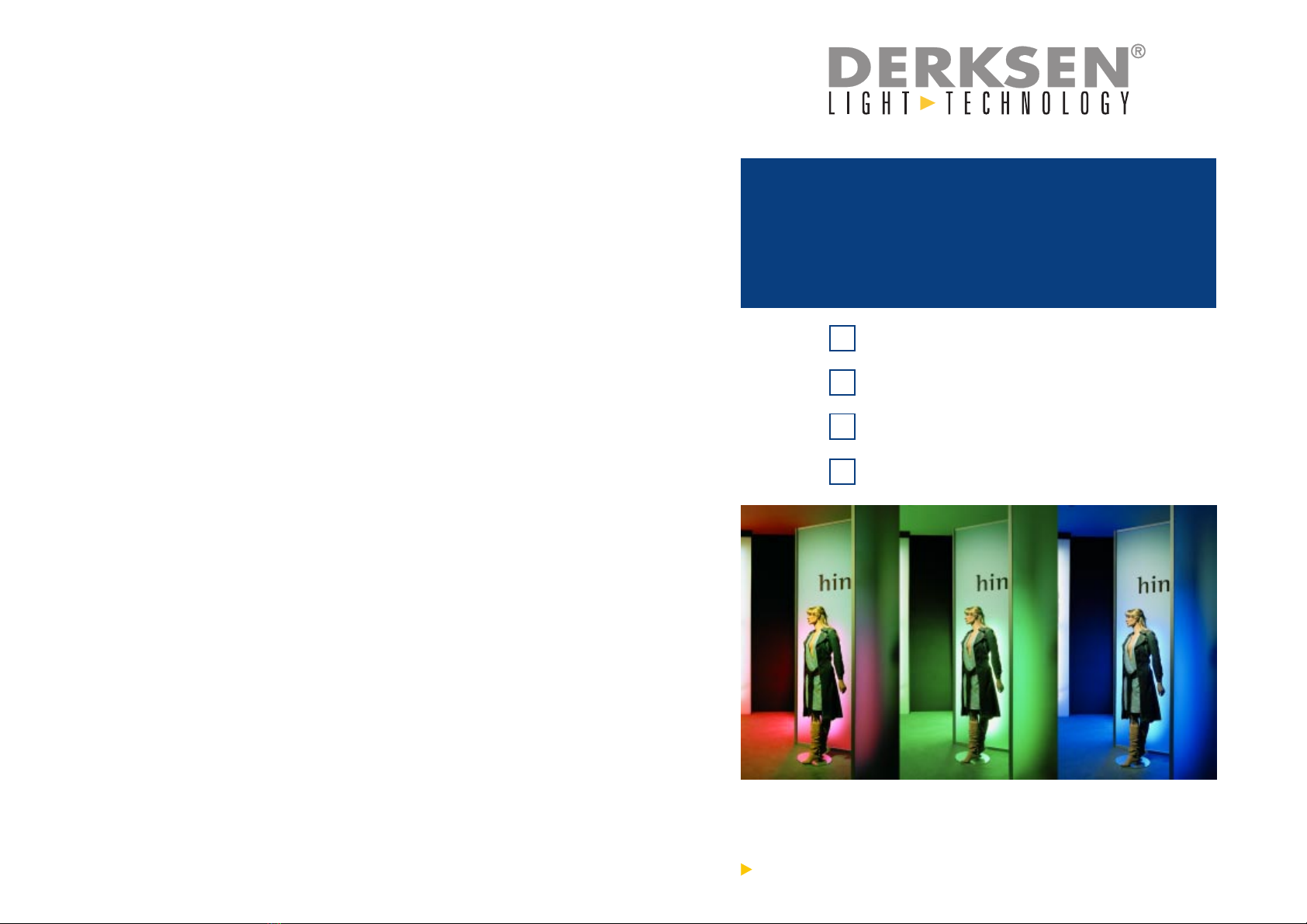
Manual
Lightbrush
®
rgb-Module
Lightbrush
®
rgb-Cube
rgb-Module 1500
rgb-Module 1200
rgb-Module 590
rgb-Cube
230 V Version

2
Protect units against humidity.
Operate LIGHTBRUSH®RGB modules only within dry, closed premises.
Do not use faulty cables.
Make sure you disconnect the power plug before cleaning or opening the unit, or
before changing lamps.
In case of unexpected failure, unplug unit and have it examined.
All Units should be serviced by a qualified technician only.
Use only parts and accessories approved by DERKSEN® Light Technology.
Install the units only on firm, flat surfaces. Before their first use, the RGB
modules must be secured with screws to a floor, wall or ceiling.
Safety Precautions
1
User Instructions for
Lightbrush®rgb-Module / RGB-Cube
Before switching the unit on for the first time, please read these instructions and
keep them in a safe place!
Table Of Contents
Safety Precautions ............................................................................. 2
Installation and Connection .............................................................. 3
Wall, Floor or Ceiling Installation ......................................................... 3
Cable Connection and Routing ............................................................ 4
Plug Designations for Data/Power Connections .................................. 4
LIGHTBRUSH®Slave Unit Operation .................................................. 5
LIGHTBRUSH®Infrared Receiver ........................................................ 5
How to Configure Lightbrush®
for Evenly Distributed Illuminations................................................. 6
Formular for the Illumination of
Light Areas, Light Walls, Light Ceilings etc. ........................................ 9
Operation and Programming ............................................................ 8
Basic Features ..................................................................................... 8
Preset Programs (Factory Settings) .................................................... 9
Modification of Preset Programs ........................................................ 10
Creating Custom Colour Sequences ............................................. 11/12
DMX 512 control (optional) ........................................................ 13/14
Replacing the Fluorescent Lamps ................................................. 15
Changing the Battery (Remote Control) ........................................ 15
Cleaning the Unit ............................................................................. 15
Technical Specifications ....................................................... 16/17/18

blue (B)
green (G)
red (R)
N
L
0-10 V
230 V
blue (B)
green(G)
red (R)
N
L
Data/Power-Connection Plug Data/Power-Connection Connector
Plug Designations for Data/Power Connections:
Caution: The plug and the connector (WIELAND type) are under
control power (0-10 Volt) and under mains power (230 V).
Cable Connection and Routing
Connect the power cable of the LIGHTBRUSH®master module to a wall outlet (230
V/50 Hz). Fuse (circuit breaker): 16 Amps.
In order to connect a LIGHTBRUSH®slave module to the master unit, you need only
one cable (data bus/power connection, 7-pin) that feeds the unit with power and
transmits the control signal. If several LIGHTBRUSH®slave modules are to be used,
the slave modules are connected to each other. Each slave module is connected to
the subsequent slave module with a cable (data bus/power connection, 7-pin) that
feeds the unit with power and transmits the control signal.
Ensure that you plug the 7-pin plug according to its colour coding firmly into the
connector socket until it is firmly seated and secured by the locking mechanism. To
release the locking mechanism press the black button on top of the plug. The plug
must not be exposed to any mechanical stress. Therefore, please ensure that all
cables are routed correctly. The data/power line is available in lengths between 0.5 m
and 25 m.
All cables must be protected against mechanical stress.
Data bus/ power cables routed over walls or ceilings must be secured at regular
intervals of 2 m (at least once per meter). Cables routed on floors require additional
protection against mechanical stress (such as being stepped on).
Cables may be protected with ducts or tubes, e.g. When routing cables, always verify
that there is no pull on the plugs.
4
Installation and Connection
Foor, Wall or Ceiling Installation
Select a firm, flat surface. The LIGHTBRUSH®RGB module can be used only once
it has been securely screwed to a floor, wall or ceiling. It is necessary to screw the
unit tightly to its location, in order to prevent it from tilting, sliding or dropping. Proceed
as follows to securely mount the LIGHTBRUSH®RGB module:
Example for Securing the Unit with Screws to a Wooden Floor:
Position the LIGHTBRUSH®RGB module on the selected location and align it. 1,500
mm and 1,200 mm RGB modules provide for 8 mounting screws, the 590 mm RGB
modules provide for 4 mounting screws. Mark the position of the 8 (4) mounting holes
on the side of the housing to the floor, wall, or ceiling. Pre-drill holes on the wooden
floor ensuring that the size of the holes matches the size of the screws and the strength
of the wood.
We recommend to use 8 (4) 5 x 40 mm Spax wood screws.
Screw the LIGHTBRUSH®module firmly to the floor, wall, or ceiling. Routinely check
the screws to ensure that they are tightened.
Important Note: The mounting method described here serves as an example only!
Use proper mounting materials for installation on other materials.
3
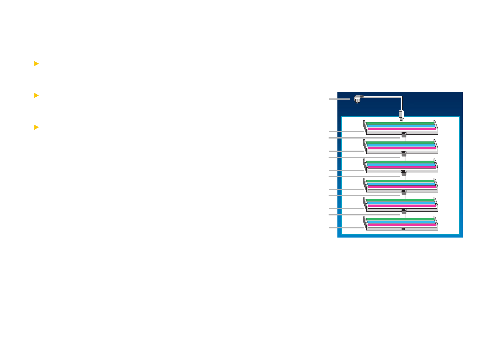
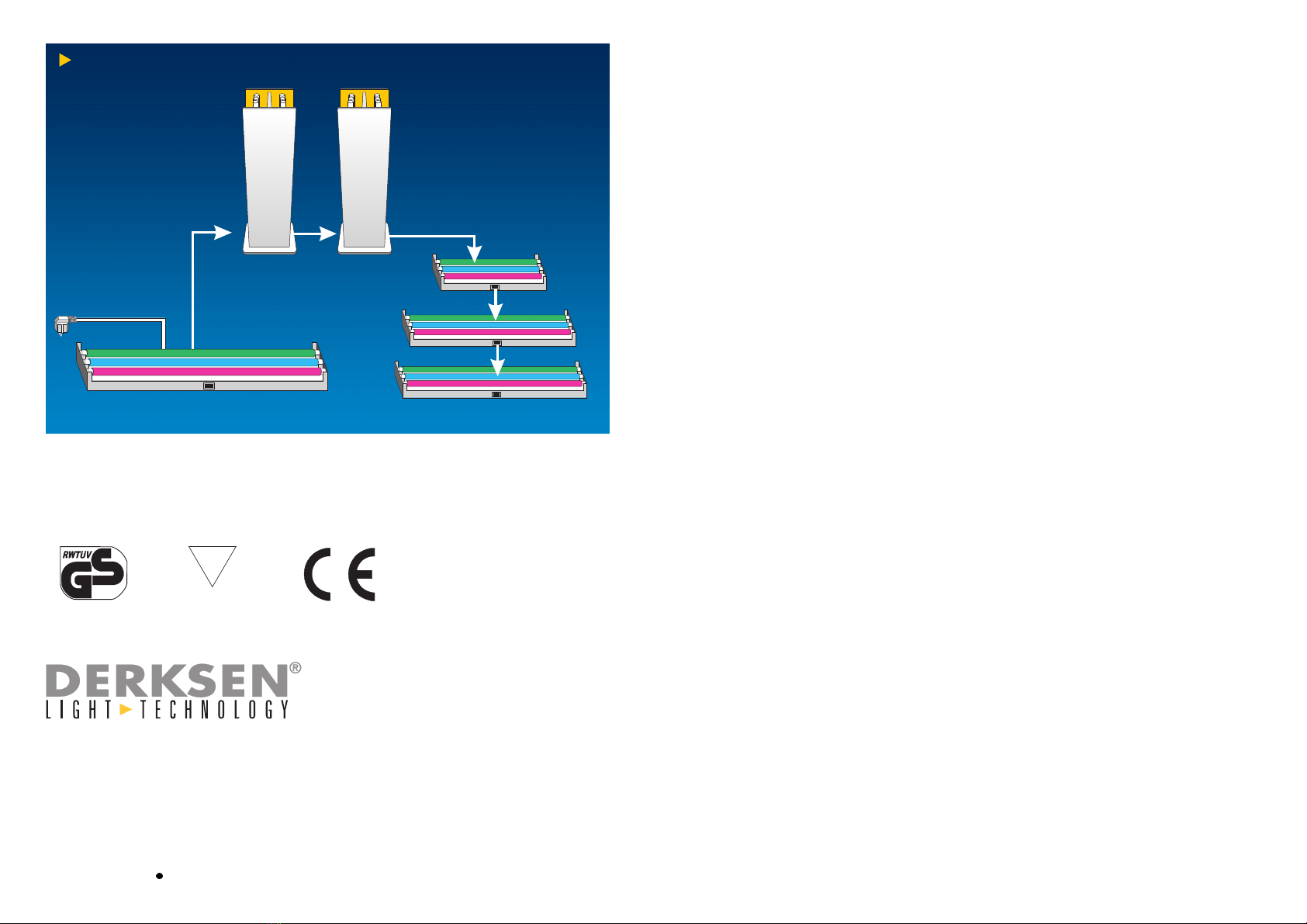
Example for Illumination of an Area
(such as a wall area measuring 2000x2000x400 mm in W/H/D):
Power Cabel
MASTER-Module 1500
Data/Power Connection
SLAVE-Module 1500
SLAVE-Module 1500
SLAVE-Module 1500
SLAVE-Module 1500
SLAVE-Module 1500
Data/Power Connection
Data/Power Connection
Data/Power Connection
Data/Power Connection
6
LIGHTBRUSH®Slave Unit Operation
Since the LIGHTBRUSH®master unit provides the master-slave set-up with power,
the entire unit is switched on and off through the master unit.
Please refer to the maximum possible number of LIGHTBRUSH®Slave Modules:
The maximum capacity of the LIGHTBRUSH®master module is 3200 VA. The
maximum number of slave modules for operation with a LIGHTBRUSH®master
module depends on total power consumption. The power consumption of the
slave units must not exceed 3200 VA!
The maximum control power of the LIGHTBRUSH®master module suffices to
control 30 units. You may exceed the maximum number of 30 units if you choose
to connect lower power consumption slave modules (such as LIGHTBRUSH®Slave
Module 590) to the LIGHTBRUSH®master module.
If the power consumption of the slave units exceeds a total of 3200 VA and/or if
more than 30 units are to be connected to the master unit, the system can be
expanded with a LIGHTBRUSH®Intermediate Amplifier (Item No. 09918600). The
amplifier automatically amplifies the capacity and control power - for an additional
30 units and a possible additional intermediate amplifier.
Infrared Receiver for LIGHTBRUSH®Remote Control
The LIGHTBRUSH®master module is equipped with an IR receiver (infrared receiver).
It connects to the side of the master module with a 1.5 m cable. Depending on the
location and position of your set-up, mount the IR receiver so that it allows for easy
remote control pointing. Please ensure that the receivers infrared sensor is not
obstructed. Where possible, the receiver should be installed outside of the boundaries
of your wall/floor/ceiling set-up.
5
8
Your LIGHTBRUSH®colour light system is ready for use after you have installed and
correctly connected the master and slave modules as previously described. Before
operating the units and designing your own colour programs please ensure that the
power plug is plugged in.
Basic Features:
Your Lightbrush®colour-light-system is ready for use after plug-in. The system will
rest in stand-by-mode and can be switched on/off by remote control (button ON/
OFF).
Even if the system is unplugged or a power failure takes place, your personal settings
and programs will not be deleted. The microprocessor is equipped with a memory
function that will preserve the most recent settings and programs. When you switch
the system on it will start up in the last operation mode.
The universal Remote Control (part # 09918100) is compatible with all Lightbrush®
Systems. It is necessary for controlling and programming. Direct your remote control
close to your colour light system [no hyphens]. When you press a button, a short
acoustic signal (beep) will sound to confirm that your command is received. If there
is no acoustic signal, your command can not be executed because you have already
reached maximum or minimum settings. For example: you push the button BRIGHT
several times until maximum brightness is reached. If you keep on pushing BRIGHT
there will be no acoustic signal because brightness cannot be increased anymore.
If there is no acoustic signal at all, please make sure that your Lightbrush®system is
plugged in and power is switched on. Please hold the remote control close enough to
the system and point directly towards it.
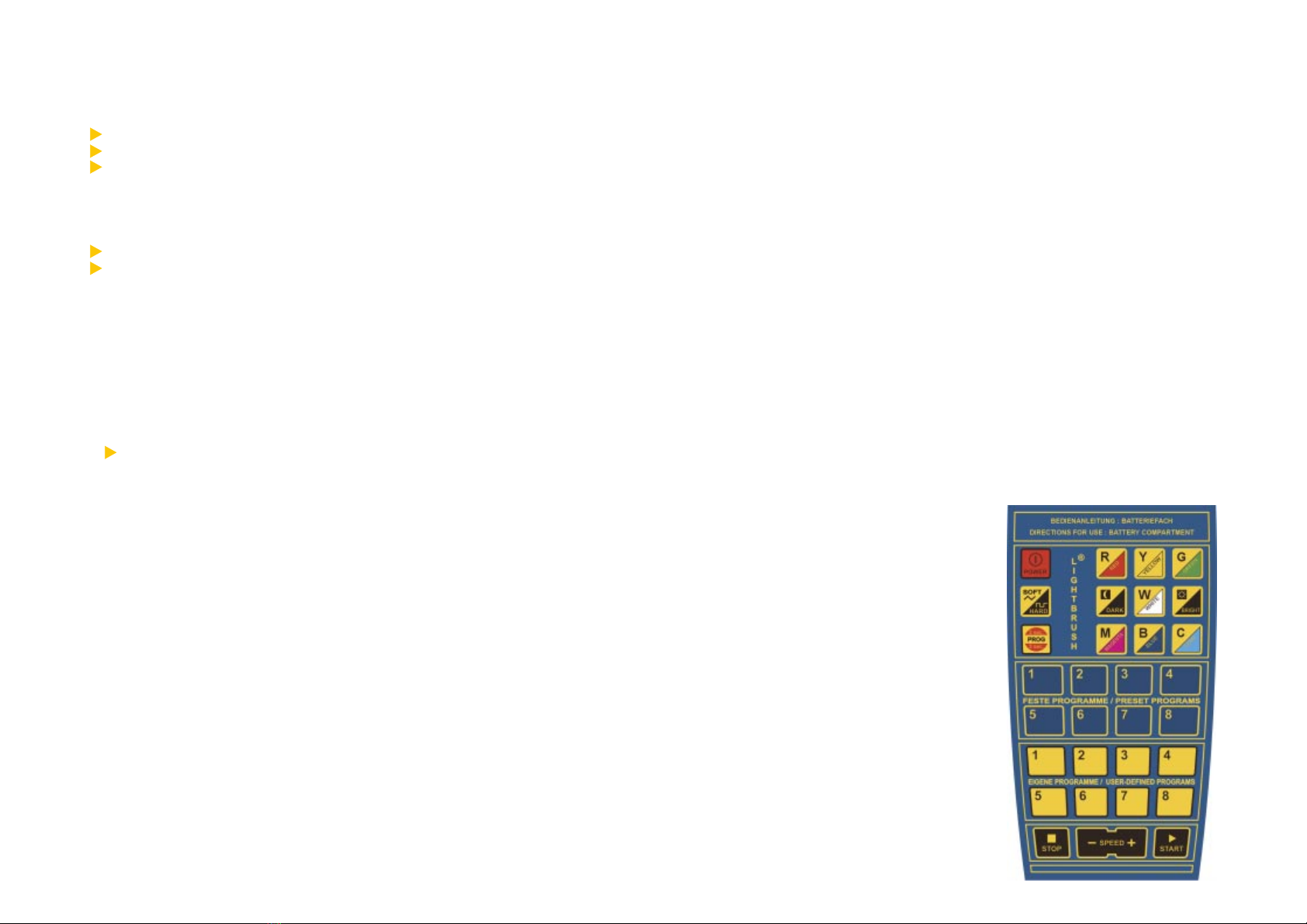
Operation and Programming
LIGHTBRUSH®Remote Control:
all functions at one glance...
7
How to Configure Lightbrush®for Evenly Distributed Illuminations
For the colour illumination of an area, certain aspects should be considered during
planning/installation:
the depth of the housing
the transparency of the front pane
the number of modules
It is important that the 16.7 million colour shades of the LIGHTBRUSH®RGB system
have an even and colour-homogenous appearance.
no shadow formation
no detection of individual fluorescent lamps
1. The ideal housing depth ranges between 300 and 400 mm. The housing depth
equals the distance between the back and the front pane (such as Plexiglas with a
47% transparency, film or gauze).
Smaller depths (such as 200 mm) are possible, but this would require more modules
for even illumination.
2. Formular for Determinig the Number of Required
LIGHTBRUSH®RGB-Module
Housing depth x 0.8 = distance between modules
(distance to be measured from module centre to module centre)
The following example demonstrates that the required number of RGB modules
for an area of 2,000 x 2,000 mm depends on the housing depth:
2.1 Housing depth 200 mm x 0.8 = 160 mm distance,
consequently, 12 Modules 1,500 mm are required for a 2,000 x 2,000 mm
area.
2.2 Housing depth 300 mm x 0.8 = 240 mm distance,
consequently, 8 Modules 1,500 mm are required for a 2,000 x 2,000 mm
area.
2.3 Housing depth 400 mm x 0.8 = 320 mm distance,
consequently, 6 Modules 1,500 mm are required for a 2,000 x 2,000 mm
area.
2.4 Housing depth 500 mm x 0.8 = 400 mm distance,
consequently, 4 - 5 Modules 1,500 mm are required for a 2,000 x 2,000 mm
area.
With increased housing depths and less RGB modules, the light intensity of the area
illumination will decrease accordingly. A certain number of modules should be
considered. In our example, optimum results are obtained with a housing depth of
400 mm and a total of 6 LIGHTBRUSH®RGB modules (2.3).
10
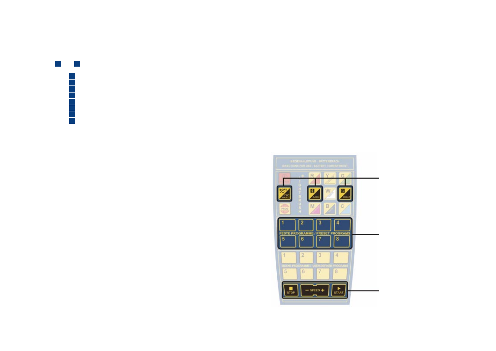
Blue buttons for direct selection
of a preset colour change
program (factory settings)
Button for individual modification
of a running colour change
program
Modification of Preset Programs:
Any colour change program can be modified during operation by the colour
control functions of your remote control:
Button DARK: brightness of all colours will be decreased.
Button BRIGHT: brightness of all colours will be increased.
Button SPEED: speed of changing can be adjusted
(range: 1 - 255 seconds per each single colour).
Button STOP: colour change will be frozen.
Button START: colour change will be started.
Button SOFT-HARD:transition mode of colours can be changed:
SOFT = smooth, slow transition of colours;
HARD= abrupt, fast change of colours
9
Buttons for start, stop and
adjusting the speed of a running
colour change program
1. Preset Programs (Factory Settings)
After you switched the colour light system on, you can immediately select one of
the preset programs. If you want to know how to create your own colour change
program, please proceed to chapter 2.
Select one of the preset programs with the blue buttons on your remote control
(from 1to 8):
blue button 1 : displaying all colours, following the RGB-concept.
blue button 2 : displaying only red colours.
blue button 3: displaying only green colours.
blue button 4 : displaying only blue colours.
blue button 5: Spring displaying green, yellow and orange colours
blue button 6: Summer displaying red, pink and blue colours
blue button 7: Autumn displaying red, brown and yellow colours
blue button 8: Winter displaying white light with shifting brightness
Note: the selected program runs in an endless loop. After you pushed a button,
there is a delay of approximately 1 second until the selected program starts.

12
Use the blue buttons to access
the individual scenes of your
colour change program.
Use the yellow buttons to save
up to 8 of your own colour
change programs.
Use the PROGRAMM button to
access the programming. To
activate it, hold the button for
approx. 3 seconds.
The Colour Control Field
Colours can be mixed easily following the colour palette concept:
Button R (red): part of red light will be increased.
Button Y (yellow): part of yellow light will be increased.
Button G (green): part of green light will be increased.
Button DARK: brightness will be decreased.
Button BRIGHT: brightness will be increased.
Button W (white): part of white light will be increased.
Button M (magenta): part of pink light will be increased.
Button B (blue): part of blue light will be increased
Button C (cyan): part of green-blue light will be increased
User-defined programs will be overwritten automatically when you assign a
new program to a place (yellow buttons from 1 - 8 ) that is already occupied
by an old program.
Modification Of User-Defined Programs:
Any colour change program can be modified during operation by the colour control
functions of your remote control (see: Modification of Preset Programs, p. 10).
11
2. Creating Custom Colour Sequences:
UIn order to adapt the colour light system to individual requirements, it is possible
to create and store user-defined colour change programs. Therefore you can
define step by step every single scene of your program. Up to 8 different user-
defined programs can be stored and assigned to the yellow buttons of the remote
control. The programs can be recalled at any time, even after a power failure
(memory function!). Please follow the instructions below:
Step 1: Push the button PROGRAMM for approx. 3 seconds to enter the
programming mode.
Step 2: Push one of the yellow buttons (eg. 1) in order to assign your program
to it. Later you can recall your program by pushing it.
Step 3: Using the blue buttons (from 1- 8) you can select a single scene of
your colour change program. Please press the blue button 1to define
colour for the first scene.
Step 4: Adjust the colour of the first scene by the colour control functions of
your remote control. Only when you are satisfied with the selected colour
continue with the second scene
Step 5: Press the blue button 2, to define colour for the second scene of your
program.
Step 6: Adjust the colour of the second scene by the colour control functions
of your remote control. Only when you are satisfied with the selected
colour continue with the third scene
Step 7: Select additional scenes with the blue buttons 3- 8and adjust the
colour for each single scene.
Step 8: Press the button PROGRAMM to end programming mode. Now the
complete program can be recalled and started by the yellow button 1.
Create other colour change programs following the instruction above. A maximum
number of 8 programs can be stored (yellow buttons 1- 8 ).
Note:
During programming, previous scenes can be recalled by the blue buttons, in
order to test or adjust the colour of a previous scene.
A colour change program may consist of less than 8 scenes. Once you are
satisfied with the number of scenes, just press the button PROGRAMM to
end programming.
Colour Control Field
14
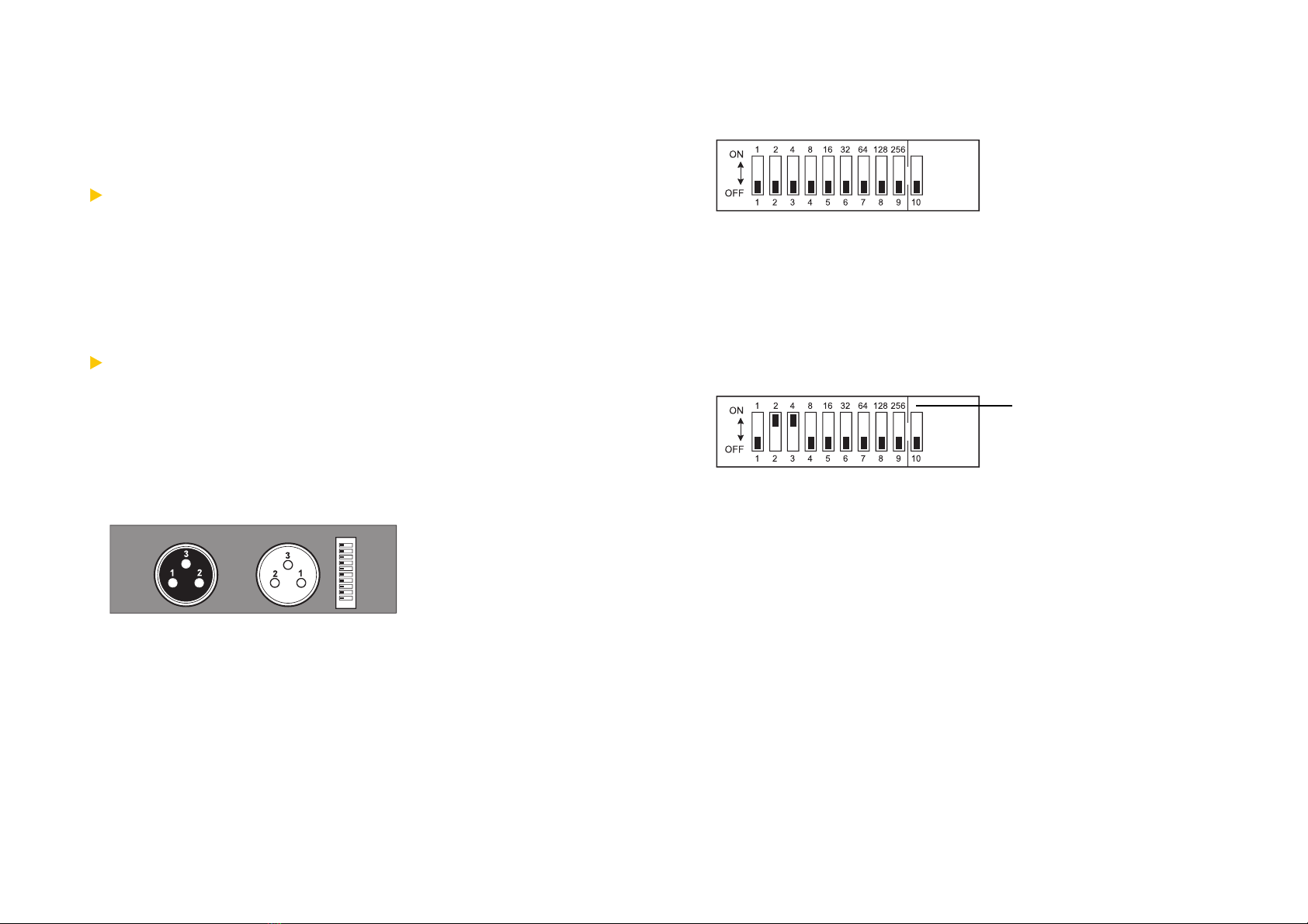
Example: Selecting DMX-Channel 6
Values Assigned to Switches
13
DMX 512 Control (optional)
LIGHTBRUSH®systems can be controlled with an optional supplementary DMX 512
board. The board can be ordered directly from DERKSEN®Lichttechnik. The
supplementary board is installed in the housing of the LIGHTBRUSH®master module
and connects to the main board with a ribbon cable. The standard DMX input and
output ports are accessible from the exterior of the housing.
Important for the safety of your system: The supplementary board complies with
all requirements under the new international DMX 512 A standard:
The input and output ports are galvanically balanced.
The DMX data is utilized only if the start code value is 0.
The DMX 512 A is backward-compatible with existing DMX standards.
Certified Quality: The supplementary DMX 512 board of DERKSEN®Lichttechnik
has been certified under the terms of the German technical control board (TÜV)!
All components of the LIGHTBRUSH®colour light system have the GS mark (safety-
tested) and the CE mark (compliance with European safety standards).
Supplementary DMX 512 Board Connections:
Setting the DIP Switches at the DMX 512 Connection:
Switches 1-9 are used to select the DMX channels. In the ON position, the value
assigned to the switch will be added to the total value. Example: Switch 2 (value 2)
and switch 3 (value 4) are set to ON. This results in the selection of channel 6
(value 2+4). No function has been assigned to switch 10.
Remote control operation is switched automatically to DMX control once the ribbon
cable is plugged into the main board.
3-pin WLR Plug
Pin Settings:
1 - GND
2 - DATA
3 - DATA +
DIP-SwitchDMX 512
Input Port
DMX 512
Output Port
DIP-Switches 1-9:
Channel Selection

16
Technical Specifications:
WiImportant notes for electricians, in accordance with the recommendations of OS-
RAM and PHILIPS:
Operation within an electrical circuit that is protected against fault current (fault
current switch):
FFI switch (fault current protection switch - surge protector) - 30 mA:
maximum 10 LIGHTBRUSH®columns, or
maximum 10 LIGHTBRUSH®modules 1500, or
maximum 10 LIGHTBRUSH®modules 1200, or
maximum 10 LIGHTBRUSH®modules 590, or
maximum 10 LIGHTBRUSH®Cubes.
Explanatory Note: Switches of this type contain Y condensers that work against the
EARTH and consequently reduce fault current.
15
Replacing the Lamps
For economic reasons, we suggest to replace the entire lamp set, even if only one
lamp fails. Use only fluorescent lamps as recommended by the manufacturer. Ensure
that the replacement lamps have the proper length and wattage.
Caution: The lamps come in three colours (red - green - blue), even though the glass
tube itself appears as uniformly white. Please refer to the written specifications printed
on the fluorescent lamps!
Protect yourself against electrical hazard by unplugging the unit before
proceeding!
Unlock faulty lamps by turning them 90°, and remove the lamp.
Insert the replacement lamp with the appropriate colour into its assigned socket.
Ensure to follow the colour coding (red - green - blue) in the housing and the
specifications printed on the lamp.
Lock the replacement lamp in place by turning it 90°.
The RGB module is now again ready for use.
LIGHTBRUSH®Master-Module 1500:
Item No. 09916200
Colour Light Module with Control Unit
Type: RGB 1500 / Master
W/H/D: 1546 x 87.5 x 153 mm
Housing: Alu-polished
Weight: 4.1 kg
Power Input Plug 230 Volt, 16 A
Rated Power (Consumption): 180 VA
Power Output: 3200 VA
Features:
Microprocessor for the control of 16.7
million colours, can be controlled and
programmed with (optional) remote
control, 3 1500 mm RGB fluorescent
lamps, 58 W each, data bus connector/
power connection to control slave mo-
dules.
Slave module connection up to 3200 VA,
depending on power supply.
LIGHTBRUSH®Slave-Module 1500:
Item No. 09916300
Colour Light Module without Control Unit
Type: RGB 1500 / Slave
W/H/D: 1546 x 87.5 x 153 mm
Housing: Alu-polished
Weight: 4.0 kg
Rated Power (Consumption): 180 VA
Features:
3 1500 mm RGB fluorescent lamps, 58
W each, data bus connector/power
connection for the operation of additio-
nal slave columns, without control unit
and remote control.
Changing the Battery
The universal remote control operates with a commercial 9 V block battery. Open
the battery compartment on the back of the remote control and replace the old
battery with a new one.
Cleaning the Unit
Only the exterior of the unit may be cleaned. For interior cleaning, please contact an
authorized technician or ship the unit to the manufacturers factory.
Housing Exterior: Clean the exterior with a dry, soft cloth. Do not use cleaning solutions
such as alcohol since this could damage the colour. Do not use compressed air,
sprays or similar means.

1817
Subject to technical and optical modifications!
LIGHTBRUSH®Master-Cube:
Item No. 09919100
Colour Light Cube with Control Unit
Type: RGB 2 x 590 / Master
W/H/D: 640 x 640 x 340 mm
Housing: Sheet steel, white
Weight: 13.0 kg
Power Input Plug 230 Volt, 16 A
Rated Power (Consumption): 120 VA
Power Output: 3200 VA
Features:
Microprocessor for the control of 16.7
million colours, can be controlled and
programmed with (optional) remote
control, 6 590 mm RGB fluorescent
lamps, 18 W each, data bus connector/
power connection to control slave cubes.
Slave unit connection up to 3200 VA,
depending on power supply.
LIGHTBRUSH®Slave-Cube:
Item No. 09919200
Colour Light Cube without Control Unit
Type: RGB 2 x 590 / Slave
W/H/D: 640 x 640 x 340 mm
Housing: Sheet steel, white
Weight: 12.7 kg
Rated Power (Consumption): 120 VA
Features:
6 590 mm RGB fluorescent lamps, 18
W each, data bus connector/power
connection for the operation of additio-
nal slave cubes, without control unit and
remote control.
LIGHTBRUSH®Master-Module 1200:
Item No. 09916400
Colour Light Module with Control Unit
Type: RGB 1200 / Master
W/H/D: 1246 x 87.5 x 153 mm
Housing: Alu-polished
Weight: 3.6 kg
Power Input Plug 230 Volt, 16 A
Rated Power (Consumption): 120 VA
Power Output: 3200 VA
Features:
Microprocessor for the control of 16.7
million colours, can be controlled and
programmed with (optional) remote
control, 3 1200 mm RGB fluorescent
lamps, 36 W each, data bus connector/
power connection to control slave mo-
dules.
Slave module connection up to 3200 VA,
depending on power supply.
LIGHTBRUSH®Slave-Module 1200:
Item No. 09916500
Colour Light Module without Control Unit
Type: RGB 1200 / Slave
W/H/D: 1246 x 87.5 x 153 mm
Housing: Alu-polished
Weight: 3.5 kg
Rated Power (Consumption): 120 VA
Features:
3 1200 mm RGB fluorescent lamps, 36
W each, data bus connector/power
connection for the operation of additio-
nal slave columns, without control unit
and remote control.
LIGHTBRUSH®Master-Module 590:
Item No. 09916600
Colour Light Module with Control Unit
Type: RGB 590 / Master
W/H/D: 1246 x 87.5 x 153 mm
Housing: Alu-polished
Weight: 2.5 kg
Power Input Plug 230 Volt, 16 A
Rated Power (Consumption): 60 VA
Power Output: 3200 VA
Features:
Microprocessor for the control of 16.7
million colours, can be controlled and
programmed with (optional) remote
control, 3 590 mm RGB fluorescent
lamps, 18 W each, data bus connector/
power connection to control slave mo-
dules.
Slave module connection up to 3200 VA,
depending on power supply.
LIGHTBRUSH®Slave-Module 590:
Item No. 09916700
Colour Light Module without Control Unit
Type: RGB 590 / Slave
W/H/D: 1246 x 87.5x 153 mm
Housing: Alu-polished
Weight: 2.4 kg
Rated Power (Consumption): 60 VA
Features:
3 590 mm RGB fluorescent lamps, 18
W each, data bus connector/power
connection for the operation of additio-
nal slave columns, without control unit
and remote control.
DERKSEN® Lichttechnik GmbH
Sauerlandstraße 5
D-45889 Gelsenkirchen
phone: +49 (0)209/9 80 70-0
fax: +49 (0)209/9 80 70-60
e-mail: [email protected]
www.derksen.de
l
www.lightbrush.de
LIGHTBRUSH® Slave-Modules
LIGHTBRUSH® Slave-Columns
LIGHTBRUSH® Master-Module (or Column)
All LIGHTBRUSH® Systems can be combined with each other!
Safety:
All LIGHTBRUSH®Systems have the following test certificates:
F
geprüfte
Sicherheit
EN 60598
EN 61547 (Interference Resistance)
EN 50081-1 (Emission)
Date of Issue: September 2003. Copyright © 2003 by DERKSEN® Lichttechnik GmbH
This manual suits for next models
3
Other Derksen Lighting Equipment manuals


