TB-2082 Page 5 of 6 © 2009 DESCO INDUSTRIES, INC.
Employee Owned
Step 6: Rotate the selector knob clockwise to the “HIGH
FAIL” position. The green “OPERATOR GROUND” LED
should turn off and the red LED should illuminate and the
alarm should sound.
Step 7: Disconnect the Monitor Calibration Unit from the
monitor.
TESTING THE MAT CIRCUIT
Step 1: Connect the Calibration Unit’s banana plug wire
labeled “GROUND” to a known ground.
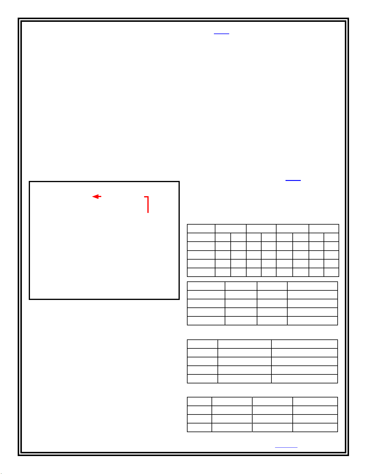
Step 2: Connect the included banana jack to wire adapter to
the Calibration Unit’s banana plug labeled “MAT.” Insert the
other end of the wire to the monitor’s green terminal block
labeled “MAT” (see Figure 9).
Step 3: Rotate the Calibration Unit’s knob switch to the MAT
FAIL 10M position. The monitor’s red “WORKSURFACE
GROUND” LED should illuminate and the alarm should
sound.
Note: The 98220 Monitor Calibration Unit also calibrates the
following discontinued Desco items:
Full Time Continuous Monitor
19210, 19211, 98210, 98211
Dual Operator Continuous Monitor with Satellites
19208, 19209, 19230, 19231, 98207, 98208
Jewel®Workstation Continuous Mini Monitor
19213, 19214, 19215, 19216, 19217
Multi-Mount Continuous Monitor
19220, 19221, 19222, 19223, 98225, 98226, 98227, 98228
Calibration
Required Test Equipment: RLC Bridge
Settings:
For 50 Hz, Frequency = 1,000 Hz (20 x 50), 20th Harmonic
For 60 Hz, Frequency = 1,020 Hz (17 x 60), 17th Harmonic
Set function switch to read “equivalent parallel circuit”
Additional Required Test Equipment for 98220 MAT
Resistance Measurement:
Megger: Set V compliance = 50V or less
or
DMM: 50V power supply
Record Data for:
Figure 9. Connecting the MAT test lead from the Monitor
Calibration Unit to the
Multi-Mount Continuous Monitor
Step 4: Rotate the selector knob counter-clockwise to the
MAT PASS 10M position. The monitor’s “WORKSURFACE
GROUND” green LED should illuminate.
Specifications
Weight: 6.8 oz
192 g
Dimensions: 4.5" x 2.5" x 1.2"
11.4 cm x 6.4 cm x 3.0 cm
Low Pass Low Fail High Pass High Fail
Serial # Cp Dis Cp Dis Cp Dis Cp Dis
Serial # Mat Pass Mat Fail Megohms @ 50V
Compare with the following specs (tolerance = ± 10%):
Equiv. Parallel C Dissipation Factor
Low Fail 138.9 pF 0.158
Low Pass 118.6 pF 0.367
Hi Pass 49.0 pF 0.445
Hi Fail 44.7 pF 0.192
Pass Fail V Measure ~ 50
10 Mat 8 Megohms 12 Megohms
100 Mat 80 Megohms 120 Megohms
500 Mat 400 Megohms 600 Megohms
Mat (tolerance = ± 4%):