manuals.online logo
Brands
  1. Home
  2. •
  3. Brands
  4. •
  5. YASKAWA
  6. •
  7. Controllers
  8. •
  9. YASKAWA MOTOMAN-NX100 Parts list manual

YASKAWA MOTOMAN-NX100 Parts list manual

Interface panel function
MOTOMAN-NX100
Upon receipt of this product and prior to initial
operation, read these instructions thoroughly,
and retain for future reference.
© 2006 MOTOMAN Robotics Europe AB · Reg No.: MRS6036EN.0.U
Page 2 Revised: 07-04-24 Controller_front.fm
Reference list
This manual is a revised version of the YEC document:
HW0482596.4
Revision
2007-04-24
First release of this manual.
MRS6036EN.0.UTOC.fm Revised: 07-04-24 Page 3
Interface panel function
1. Outline of interface panel function 5
2. Display and operations of panel screen 7
Interface panel display .................................................................................7
3. Data setting and touch panel I/F instructions 13
Setting procedure ........................................................................................14
Details on interface panel setting items ....................................................23
4. Save and load of set data 29
5. Editing saved data 31
6. Parameters 35
Clearing the status of signals .....................................................................35
Allocation of general input signals to interface panel screens ................37
Interface panel function
Page 4 Revised: 07-04-24 MRS6036EN.0.UTOC.fm
MRS6036EN-ch1.fm Revised: 07-04-24 Page 5
Interface panel function
1. Outline of interface panel function
This function makes the system construction simple and enables the reduction of operation
panel and Interlock panel (hereinafter called "I/L panel") by holding the roles of operation
panel and I/L board in the programming pendant (hereinafter called "PP").
Users can construct the arbitrary operation panel for PP by setting data in Interface panel set-
ting screen.
Interface panel function
Page 6 Revised: 07-04-24 MRS6036EN-ch1.fm
MRS6036EN-ch2.fm Revised: 07-04-24 Page 7
Interface panel function
Interface panel display
2. Display and operations of panel screen
2.1 Interface panel display
! Panel screen display
Follow the operations as below to display the Interface panel.
Information!
Due to some conditions during an operation, Interface panel may not appear on the screen.
In that case, the massage “Cannot display at current operation mode” appears when {I/F
Panel} is pressed.
Operation Explanation
1Press {I/F panel} to display
the interface panel screen.
2
Press {I/F panel} while the
interface panel appears on
the screen.
The screen goes back to the previous display.
Short Cut
Main Menu I/F Panel
JOB
DOUT
MOVE
END
VARIABLE
B001
IN/OUT
In Out
ROBOT
SYSTEM INFO
CF
FD/CF
ARC WELDING SETUP
DISPLAY SETUP
A
a
JOB CONTENT
JOB NAME MOTOMAN
CONTROL GROUP R1 TOOL **
STEP NO
0000
0001
0002
0003
0004
0005
0006
0007
0008
0009
NOP
LABEL
DOUT
MOVJ
MOVJ
MOVJ
MOVJ
MOVJ
JUMP
END
OT#(1)ON
VJ=100.00
VJ=100.00
VJ=100.00
VJ=100.00
VJ=100.00
LABEL
JOB EDIT
DISPLAY
UTILITY
=> MOVJ VJ=100.00
Interface panel function
Interface panel display
Page 8 Revised: 07-04-24 MRS6036EN-ch2.fm
! Panel screen operation by touch panel
Follow the operations as below to perform ON/OFF operation on the panel screen by touch
panel.
! Panel screen operation by PP keys
Follow the operations as below to perform ON/OFF operation on the panel screen by PP
keys.
Information!
Set the item "INTERLOCK ENABLE" in the I/F PANEL SETUP screen to "PERMIT", and
operations are allowed without pressing the [INTERLOCK] key.
See the item "Interlock enable" in the table "Data of each setting items" of “Details on inter-
face panel setting items” on page 23.
Operation Explanation
1
Hold down [INTERLOCK]
and select an appropriate
button on the touch panel.
Operation Explanation
1
Use the arrow key to move
to the place where ON/OFF
operation is to be
performed.
2Hold down [INTERLOCK]
and press [SELECT].
Short Cut
Main Menu I/F Panel
I/F PANEL
DATA EDIT
DISPLAY
UTILITY
=> MOVJ VJ=100.00
Panel 1 Panel 2 Panel 3 Panel 4 Panel 5
OPERATION
PROH PERM
PROH PERM
06
HIT COUNT
TYPE OF
VEHICLE
WELD ON
COUT-UP NO.
TYPE OF
VEHICLE
PRECEDING
TYPE OF
VEHICLE
PRECEDING
COOL WATER
ERR
COOL WATER
ERR
WELD
ALLOWED
WELD
ALLOWED
PLAY MODE
HOLD
TEACH MODE
OPERATION
READY
OPERATION
READY
PLAY MODE
SELECT
PLAY MODE
SELECT
HOLD
TEACH MODE
SELECT
TEACH MODE
SELECT
03
COOL WATER
ERR RESET
COOL WATER
ERR RESET
STOP WATER
SOLENOID
OPEN
STOP WATER
SOLENOID
OPEN
ATC/TOOL
MNL OPRTN
ALLOWED
ATC/TOOL
MNL OPRTN
ALLOWED
SHUTTLE OFF-
INTRFRNC
SHUTTLE OFF-
INTRFRNC
TIMER ERR
RESET
TIMER ERR
RESET
COOL WATER
SWITCH
COOL WATER
SWITCH
OPERATION
ORIGINAL
POSITION
OPERATION
ORIGINAL
POSITION
Short Cut
Main Menu I/F Panel
I/F PANEL
DATA EDIT
DISPLAY
UTILITY
=> MOVJ VJ=100.00
Panel 1 Panel 2 Panel 3 Panel 4 Panel 5
OPERATION
PROH PERM
PROH PERM
06
HIT COUNT
TYPE OF
VEHICLE
WELD ON
COUT-UP NO.
TYPE OF
VEHICLE
PRECEDING
TYPE OF
VEHICLE
PRECEDING
COOL WATER
ERR
COOL WATER
ERR
WELD
ALLOWED
WELD
ALLOWED
PLAY MODE
HOLD
TEACH MODE
OPERATION
READY
OPERATION
READY
PLAY MODE
SELECT
PLAY MODE
SELECT
HOLD
TEACH MODE
SELECT
TEACH MODE
SELECT
03
STOP WATER
SOLENOID
OPEN
STOP WATER
SOLENOID
OPEN
ATC/TOOL
MNL OPRTN
ALLOWED
ATC/TOOL
MNL OPRTN
ALLOWED
SHUTTLE OFF-
INTRFRNC
SHUTTLE OFF-
INTRFRNC
TIMER ERR
RESET
TIMER ERR
RESET
COOL WATER
SWITCH
COOL WATER
SWITCH
OPERATION
ORIGINAL
POSITION
OPERATION
ORIGINAL
POSITION
COOL WATER
ERR RESET
COOL WATER
ERR RESET
MRS6036EN-ch2.fm Revised: 07-04-24 Page 9
Interface panel function
Interface panel display
Information!
Set the following parameter to "1" to allow operations only by the touch panel (prohibiting the
operations by cursor key).
Parameter: S2C301 (IF panel operation by cursor key)
0: Enable, 1: Disable
! Numeric display
Follow the operations as below to display numeric values on the panel screen.
! Input of numeric value
Follow the operations below to input numeric values.
Information!
Numeric values cannot be entered in the preset counter during playback.
Operation Explanation
1
Set the item "PANEL TYPE"
in the I/F PANEL SETUP
screen to either "Counter" or
"Preset counter".
Numeric value will be displayed in either three-digit number or six-digit
number according to the setting of indicated value.
If the indicated value exceeds the specified number of digits (three-digit
or six-digit), an asterisk "*" appears instead of numeric value.
Three-digit display: Six-digit display:
Operation Explanation
1
Set the item "PANEL TYPE"
in the I/F PANEL SETUP
screen to "Preset counter".
2
Hold down [INTERLOCK]
and touch the icon of
"Preset counter" or move
the cursor to the icon of
"Preset counter", then press
[SELECT].
Numeric values can now be entered in the Preset counter.
Three-digit display: ⇒
Six-digit display: ⇒
3Enter numeric values with
the numeric keypad.
Numeric values in the range from -99 to 999 can be entered in the three-
digit preset counter. Numeric values in the range from -99999 to 999999
can be entered in the six-digit preset counter.
No other numeric value is unable to be set except for the possible range
of settings shown below:
<Possible range of settings>
B-variable: 0 to 255
I-variable: -32768 to 32767
Register: 0 to 65535
Interface panel function
Interface panel display
Page 10 Revised: 07-04-24 MRS6036EN-ch2.fm
! Change of panel screen
Follow the operations as below to change the file number of interface panel.
There are two ways of changing file number.
! Change of language on screen
The language can be changed only when bilingual function is enabled.
Operation Explanation
1 Press the page key .
The panel page changes one by one in the forward direction.
Hold down [SHIFT] and press to change the panel in the
backward direction
2
Instruct the page to be
shown by the Touch panel
directly.
Press [Shift] to show panel pages 6 to 10.
Operation Explanation
1
Hold down [SHIFT] and
press .
2The language on the screen
changes.
GO BACK
PAGE
GO BACK
PAGE
AREA
Short Cut
Main Menu I/F Panel
I/F PANEL
DATA EDIT
DISPLAY
UTILITY
=> MOVJ VJ=100.00
Panel 1 Panel 2 Panel 3 Panel 4 Panel 5
OPERATION
PROH PERM
PROH PERM
00
HIT COUNT
TYPE OF
VEHICLE
WELD ON
COUT-UP NO.
TYPE OF
VEHICLE
PRECEDING
TYPE OF
VEHICLE
PRECEDING
COOL WATER
ERR
COOL WATER
ERR
WELD
ALLOWED
WELD
ALLOWED
PLAY MODE
HOLD
TEACH MODE
OPERATION
READY
OPERATION
READY
PLAY MODE
SELECT
PLAY MODE
SELECT
HOLD
TEACH MODE
SELECT
TEACH MODE
SELECT
00
COOL WATER
ERR RESET
COOL WATER
ERR RESET
STOP WATER
SOLENOID
OPEN
STOP WATER
SOLENOID
OPEN
ATC/TOOL
MNL OPRTN
ALLOWED
ATC/TOOL
MNL OPRTN
ALLOWED
SHUTTLE OFF-
INTRFRNC
SHUTTLE OFF-
INTRFRNC
TIMER ERR
RESET
TIMER ERR
RESET
COOL WATER
SWITCH
COOL WATER
SWITCH
OPERATION
ORIGINAL
POSITION
OPERATION
ORIGINAL
POSITION
Panel 1 Panel 2 Panel 3 Panel 4 Panel 5
MRS6036EN-ch2.fm Revised: 07-04-24 Page 11
Interface panel function
Interface panel display
Information!
Unless panel names are set in each language mode, the panel names will not be displayed
when the screen is changed to the subject language mode.
In such a case, set the panel names in the subject language mode.
Interface panel function
Interface panel display
Page 12 Revised: 07-04-24 MRS6036EN-ch2.fm
MRS6036EN-ch3.fm Revised: 07-04-24 Page 13
Interface panel function
3. Data setting and touch panel I/F instructions
Set the security level to "Management" mode.
Follow the operations as below to open I/F panel setting screen.
Operation Explanation
1Select {SYSTEM INFO} under the
main menu.
2 Select {I/F PANEL SETUP}.
The I/F panel setting screen appears.
Short Cut
Main Menu I/F Panel
SECURITY
MANAGEMENT MODE
MODE
DATA EDIT
DISPLAY
UTILITY
JOB
DOUT
MOVE
END
VARIABLE
B001
IN/OUT
In Out
ROBOT
SYSTEM INFO
CF
FD/CF
ARC WELDING
A
a
VERSION
MONITORING TIME
ALARM HISTORY
I/O MSG HISTORY
I/F PANEL SETUP
SECURITY
Short Cut
Main Menu I/F Panel
DATA EDIT
DISPLAY
UTILITY
I/F PANEL SETUP
GROUP NAME Panel 1
ARRANGE
SETUP
PANEL TYPE
PANEL COLOR
PANEL NAME
TEXT COLOR
SECURITY
INTERLOCK ENABLE
INPUT (DISP)
OUTPUT (SETUP)
1A
VALID
SELECTOR SW
DARK RED
DARK BLUE
OPERATION
PROHIBIT
SIGNAL
SIGNAL
#10010
#10010
A
A
LEFT ON
PAGE
Interface panel function
Setting procedure
Page 14 Revised: 07-04-24 MRS6036EN-ch3.fm
3.1 Setting procedure
The following describe the process on how to set up based on the table “Example of I/F panel
setting” on page 14.
Example of I/F panel setting
Items Set data
Arrangement 1A
Setup Valid
Panel type Counter
Three-digit display
Panel color Black
Panel name
Top of the counter (1st line)
Middle of the counter (2nd line)
Bottom of the counter (3rd line)
Text color Black
Security Operation mode
Interlock enable Prohibited
Input Variable: B
B000
MRS6036EN-ch3.fm Revised: 07-04-24 Page 15
Interface panel function
Setting procedure
! I/F panel setting data and display position
Operation Explanation
1
Move the cursor to the item
"ARRANGE" in the I/F panel setting
screen, then press [SELECT].
The arrangement setting screen appears.
An item with an asterisk "*" indicates that the item has already
been set (the setting is enabled).
The display position of set data is as follows:
2
Move the cursor to the position
where the item is to be arranged
and press [SELECT].
Using the page key or the [PAGE] button changes the
control group of the arrangement setting screen and a user can
select the position where the item is to be arranged.
Short Cut
Main Menu I/F Panel
ARRANGE SELECT
GROUP NAME Panel 1
1A
*2A
3A
*4A
*1B
2B
*3B
4B
1C
*2C
*3C
*4C
*1D
*2D
3D
*4D
*1E
*2E
*3E
*4E
1F
2F
3F
4F
1G
2G
3G
4G
1H
2H
3H
4H
DATA EDIT
DISPLAY
UTILITY
PAGE
Short Cut
Main Menu I/F Panel
I/F PANEL
DATA EDIT
DISPLAY
UTILITY
Panel 1 Panel 2 Panel 3 Panel 4 Panel 5
OPERATION
PROH PERM
OPERATION
PROH PERM
1A
2A
3A
4A
1B
2B
3B
4B
1C
2C
3C
4C
1D
2D
3D
4D
1E
2E
3E
4E
1F
2F
3F
4F
1G
2G
3G
4G
1H
2H
3H
4H
GO BACK
PAGE
Interface panel function
Setting procedure
Page 16 Revised: 07-04-24 MRS6036EN-ch3.fm
! Editing of setup
! Editing of panel type
Operation Explanation
1
Move the cursor to the item
"SETUP" in the I/F panel setting
screen and press [SELECT].
The status of "SETUP" switches between "VALID" and "INVALID"
with each pressing of [SELECT].
If the items "INPUT (DISP)" and "OUTPUT (SETUP)" in the I/F panel
setting screen are not set, the status of "SETUP" cannot be set to
"VALID".
(See the no.2 "SETUP" in the table "Data of each setting items"
of " ".)
Operation Explanation
1
Move the cursor to the item "PANEL
TYPE" in the I/F panel setting
screen and press [SELECT].
The list of panel types is displayed.
2Move the cursor to the panel type to
be selected and press [SELECT].
Short Cut
Main Menu I/F Panel
I/F PANEL SETUP
GROUP NAME Panel 1
ARRANGE
SETUP
PANEL TYPE
PANEL COLOR
PANEL NAME
TEXT COLOR
SECURITY
INTERLOCK ENABLE
INPUT (DISP)
3A
INVALID
CIRCLE
BLACK
BLACK
OPERATION
PROHIBIT
NONE
INDICATION ONL
A
DATA EDIT
DISPLAY
UTILITY
PAGE
Short Cut
Main Menu I/F Panel
I/F PANEL SETUP
GROUP NAME Panel 1
ARRANGE
SETUP
PANEL TYPE
PANEL COLOR
PANEL NAME
TEXT COLOR
SECURITY
INTERLOCK ENABLE
INPUT (DISP)
3A
INVALID
CIRCLE
BLACK
BLACK
OPERATION
PROHIBIT
NONE
INDICATION ONL
A
DATA EDIT
DISPLAY
UTILITY
PAGE
CIRCLE
SQUARE 1
SQUARE 2
SELECTOR SW
COUNTER
PRESET COUNTER
MRS6036EN-ch3.fm Revised: 07-04-24 Page 17
Interface panel function
Setting procedure
! Editing of panel color
! Editing of panel name
Operation Explanation
1
Move the cursor to the item "PANEL
COLOR" in the I/F panel setting
screen and press [SELECT].
The list of panel colors is displayed.
2Move the cursor to the panel color
to be selected and press [SELECT].
Operation Explanation
1
Move the cursor to the item "PANEL
NAME" in the I/F panel setting
screen and press [SELECT].
The soft key pad screen appears.
2Enter the desired panel name up to
10 one-byte characters.
Short Cut
Main Menu I/F Panel
I/F PANEL SETUP
GROUP NAME Panel 1
ARRANGE
SETUP
PANEL TYPE
PANEL COLOR
PANEL NAME
TEXT COLOR
SECURITY
INTERLOCK ENABLE
INPUT (DISP)
3A
INDICATION ONL
A
DATA EDIT
DISPLAY
UTILITY
PAGE
BLACK
BLUE
GREEN
SKY BLUE
RED
PURPLE
YELLOW
WHITE
LIGHT GRAY
DARK BLUE
DARK GREEN
DARK SKY BLUE
DARK RED
DARK PURPLE
DARKE YELLOW
DARK GRAY
Short CutMain Menu I/F Panel
1234567890
O
I
U
Y
T
REW
Q
ASDF
ZXCV
G
B
H
N
JKL
MSpace
Result
KEYBOARD SYMBOL
P
Back
Space
DATA EDIT
DISPLAY
UTILITY
Cancel
Enter
CapsLock
OFF
MAIN PANEL
Interface panel function
Setting procedure
Page 18 Revised: 07-04-24 MRS6036EN-ch3.fm
! Editing of text color
! Editing of security
Operation Explanation
1
Move the cursor to the item "TEXT
COLOR" in the I/F panel setting
screen and press [SELECT].
The list of text colors is displayed.
2Move the cursor to the text color to
be selected and press [SELECT].
Operation Explanation
1
Move the cursor to the item
"SECURITY" in the I/F panel setting
screen and press [SELECT].
The list of security modes is displayed.
2
Move the cursor to the security
mode to be selected and press
[SELECT].
Short Cut
Main Menu I/F Panel
I/F PANEL SETUP
GROUP NAME Panel 1
ARRANGE
SETUP
PANEL TYPE
PANEL COLOR
PANEL NAME
TEXT COLOR
SECURITY
INTERLOCK ENABLE
INPUT (DISP)
3A
INDICATION ONL
A
DATA EDIT
DISPLAY
UTILITY
PAGE
BLACK
BLUE
GREEN
SKY BLUE
RED
PURPLE
YELLOW
WHITE
LIGHT GRAY
DARK BLUE
DARK GREEN
DARK SKY BLUE
DARK RED
DARK PURPLE
DARK YELLOW
DARK GRAY
Short Cut
Main Menu
I/F Panel
I/F PANEL SETUP
GROUP NAME Panel 1
ARRANGE
SETUP
PANEL TYPE
PANEL COLOR
PANEL NAME
TEXT COLOR
SECURITY
INTERLOCK ENABLE
INPUT (DISP)
3A
INVALID
CIRCLE
BLACK
BLACK
OPERATION
PROHIBIT
NONE
INDICATION ONL
A
DATA EIDT
DISPLAY
UTILITY
PAGE
OPERATION MODE
EDITING MODE
MANAGEMENT MODE
MRS6036EN-ch3.fm Revised: 07-04-24 Page 19
Interface panel function
Setting procedure
! Editing of interlock enable
Information!
Be aware that operations are allowed without pressing the [INTERLOCK] key simultaneously
if the item "INTERLOCK ENABLE" is set to "PERMIT".
! Editing of input
Operation Explanation
1
Move the cursor to the item
"INTERLOCK ENABLE" in the I/F
panel setting screen and press
[SELECT].
The status of INTERLOCK ENABLE switches between
"PROHIBIT" and "PERMIT" with each pressing of [SELECT].
Operation Explanation
1
Move the cursor to the item "INPUT
(DISP)" in the I/F panel setting
screen and press [SELECT].
The list of input items is displayed.
2
Move the cursor to the input no.
setting area on the right of {INPUT
(DISP)} and press [SELECT].
Enter the input no. with the numeric keypad and press [ENTER].
Short Cut
Main Menu I/F Panel
I/F PANEL SETUP
GROUP NAME Panel 1
ARRANGE
SETUP
PANEL TYPE
PANEL COLOR
PANEL NAME
TEXT COLOR
SECURITY
INTERLOCK ENABLE
INPUT (DISP)
3A
INVALID
CIRCLE
BLACK
BLACK
OPERATION
PROHIBIT
NONE
A
INDICATION ONL
DATA EDIT
DISPLAY
UTILITY
PAGE
Short Cut
Main Menu I/F Panel
I/F PANEL SETUP
GROUP NAME Panel 1
ARRANGE
SETUP
PANEL TYPE
PANEL COLOR
PANEL NAME
TEXT COLOR
SECURITY
INTERLOCK ENABLE
INPUT (DISP)
3A
INVALID
CIRCLE
BLACK
BLACK
OPERATION
PROHIBIT
NONE
INDICATION ONL
A
DATA EDIT
DISPLAY
UTILITY
PAGE
NONE
SIGNAL
Interface panel function
Setting procedure
Page 20 Revised: 07-04-24 MRS6036EN-ch3.fm
! Editing of group name
Operation Explanation
1Select {EDIT} from the menu on the
I/F panel setting screen.
2 Select {Group name}.
3 Type in a new group name.
Enter a new group name (up to 12 one-byte characters).
The current group name indicated in the input area can be
rewritten to a new group name by partially changing it.
Information!
For character entry operation, refer to "Character Input"
in NX100 OPERATOR'S MANUAL.
The new group name is displayed in the I/F panel setting screen.
I/F PANEL SETUP
GROUP NAME PANEL 1
#10010
#10010
A
A
DATA EDIT DISPLAY UTILITY
DOUT
MOVE
END
B001
In Out
CF
A
a
Main Menu Short Cut I/F Panel
GROUP NAME
SETUP
JOB
ARC WELDING
VARIABLE
IN/OUT
ROBOT
SYSTEM INFO
PARAMETER
DISPLAY SETUP
PAGE
ARRANGE
SETUP
PANEL TYPE
PANEL COLOR
PANEL NAME
TEXT COLOR
SECURITY
INTERLOCK ENABLE
INPUT (DISP)
OUTPUT (SETUP)
1A
VALID
SELECTOR SW
DARK RED
ATC/HAND
DARK BLUE
OPERATION
PROHIBIT
SIGNAL
SIGNAL
LEFT ON
MANUAL
I/F PANEL SETUP
GROUP NAME MAIN PANEL
#10010
#10010
A
A
DATA DISPLAY UTILITYEDIT
DOUT
MOVE
END
B001
In Out
CF
A
a
Main Menu Short Cut I/F Panel
FD/CF
SETUP
JOB
ARC WELDING
VARIABLE
IN/OUT
ROBOT
SYSTEM INFO
PARAMETER
DISPLAY SETUP
PAGE
ARRANGE
SETUP
PANEL TYPE
PANEL COLOR
PANEL NAME
TEXT COLOR
SECURITY
INTERLOCK ENABLE
INPUT (DISP)
OUTPUT (SETUP)
1A
VALID
SELECTOR SW
DARK RED
ATC/HAND
DARK BLUE
OPERATION
PROHIBIT
SIGNAL
SIGNAL
LEFT ON
MANUAL

Other manuals for MOTOMAN-NX100

1

Other YASKAWA Controllers manuals

YASKAWA V1000 Series Installation and operation manual

YASKAWA

YASKAWA V1000 Series Installation and operation manual

YASKAWA L1000A Series User manual

YASKAWA

YASKAWA L1000A Series User manual

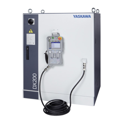
YASKAWA Motoman DX200 User manual

YASKAWA

YASKAWA Motoman DX200 User manual
YASKAWA CIMR-JC4A0002BAA User manual

YASKAWA

YASKAWA CIMR-JC4A0002BAA User manual

YASKAWA 1000-Series User manual

YASKAWA

YASKAWA 1000-Series User manual

YASKAWA Z1000 CIMR-ZU*A Series User manual

YASKAWA

YASKAWA Z1000 CIMR-ZU*A Series User manual

YASKAWA A1000 Series User manual

YASKAWA

YASKAWA A1000 Series User manual

YASKAWA A1000 Series User manual

YASKAWA

YASKAWA A1000 Series User manual

YASKAWA SGLGW User manual

YASKAWA

YASKAWA SGLGW User manual

YASKAWA iQpump 7 User manual

YASKAWA

YASKAWA iQpump 7 User manual

YASKAWA A1000 Series User manual

YASKAWA

YASKAWA A1000 Series User manual

YASKAWA MP2100 Series User manual

YASKAWA

YASKAWA MP2100 Series User manual

YASKAWA A1000 Series User manual

YASKAWA

YASKAWA A1000 Series User manual

YASKAWA MP2200 User manual

YASKAWA

YASKAWA MP2200 User manual

YASKAWA CC-Link User manual

YASKAWA

YASKAWA CC-Link User manual

YASKAWA yasnac MX2 User manual

YASKAWA

YASKAWA yasnac MX2 User manual

YASKAWA YRC1000 User manual

YASKAWA

YASKAWA YRC1000 User manual
YASKAWA PROFINET V1000 User manual

YASKAWA

YASKAWA PROFINET V1000 User manual

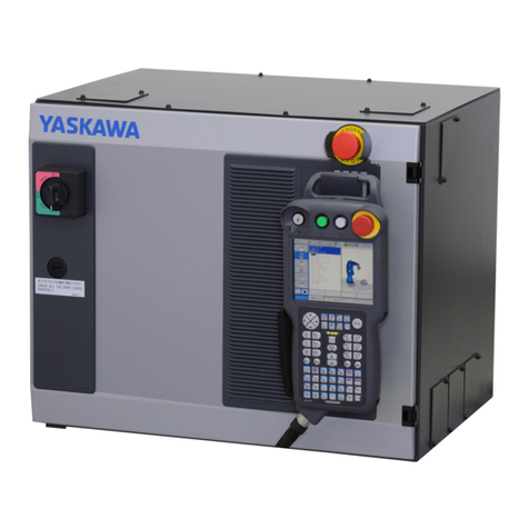
YASKAWA MOTOMAN FS100 User manual

YASKAWA

YASKAWA MOTOMAN FS100 User manual

YASKAWA Sigma II Series User manual

YASKAWA

YASKAWA Sigma II Series User manual

YASKAWA T1000V User manual

YASKAWA

YASKAWA T1000V User manual

YASKAWA T1000A User manual

YASKAWA

YASKAWA T1000A User manual

YASKAWA L1000A Series User manual

YASKAWA

YASKAWA L1000A Series User manual

YASKAWA P1000 User manual

YASKAWA

YASKAWA P1000 User manual
Popular Controllers manuals by other brands

Aeroflex 8210A-2-5 Operation & installation manual

Aeroflex

Aeroflex 8210A-2-5 Operation & installation manual

Schaudt LRM 1218 operating instructions

Schaudt

Schaudt LRM 1218 operating instructions

Mono DELTA DEPOSITOR Operation manual

Mono

Mono DELTA DEPOSITOR Operation manual

Xray XMC300R manual

Xray

Xray XMC300R manual

B&G ZEUS S Detailed App Guide

B&G

B&G ZEUS S Detailed App Guide

Honeywell UDC 2300 product manual

Honeywell

Honeywell UDC 2300 product manual

LEGRAND 038 09 Technical guide

LEGRAND

LEGRAND 038 09 Technical guide

Simon 8400700-0 Series quick start guide

Simon

Simon 8400700-0 Series quick start guide

Dometic Go Power! GP-PC Series user manual

Dometic

Dometic Go Power! GP-PC Series user manual

eltherm ELTC-21 operating instructions

eltherm

eltherm ELTC-21 operating instructions

Atlas ECS-6RM owner's manual

Atlas

Atlas ECS-6RM owner's manual

EMKO EAOM-210 FLJ user manual

EMKO

EMKO EAOM-210 FLJ user manual

PI A-824.21 Series user guide

PI

PI A-824.21 Series user guide

Huawei SmartACU2000D Series user manual

Huawei

Huawei SmartACU2000D Series user manual

Nymet WaterMe user manual

Nymet

Nymet WaterMe user manual

PTronik E10 quick start guide

PTronik

PTronik E10 quick start guide

Sonelco PCP1290 manual

Sonelco

Sonelco PCP1290 manual

AGS Merlin 1500S User & installation manual

AGS

AGS Merlin 1500S User & installation manual

manuals.online logo
manuals.online logoBrands
  • About & Mission
  • Contact us
  • Privacy Policy
  • Terms and Conditions

Copyright 2025 Manuals.Online. All Rights Reserved.