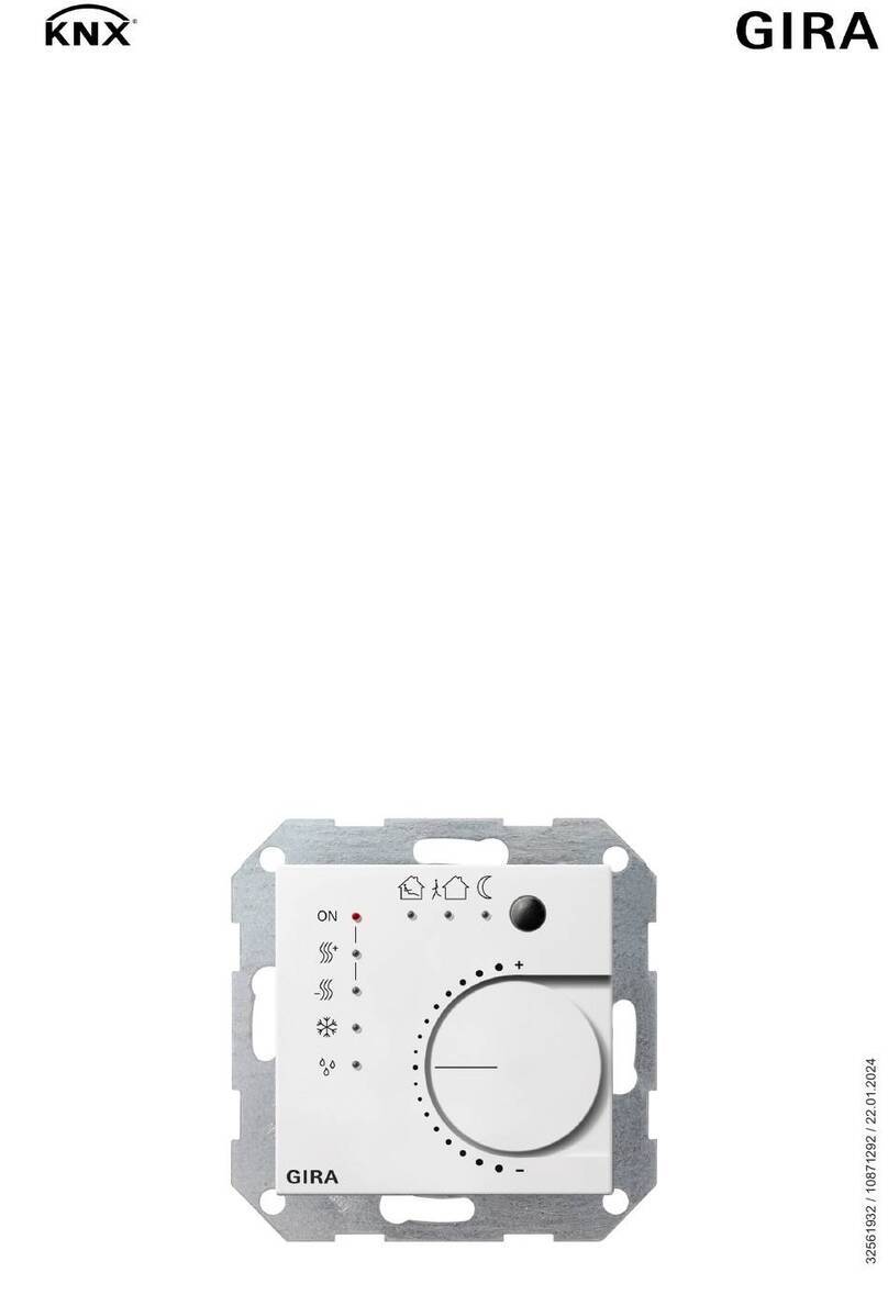
Gira 2100 Series User manual

instabus KNX/EIB System
Sensor
07/17 2100-xx/2101 xx Page 1/82
Subject to change without notice
Product name:
Continuous regulator / Object regulator
Design:
flush-mounting device (FMD)
Article-no.:
2100 xx (Continuous regulator) / 2101 xx (Object regulator)
ETS search path:
Gira Giersiepen / Input / binary input, 4-fold / continuous-action controller
Gira Giersiepen
/ Input / binary input, 4-fold / object-action controller
Gira Giersiepen
/ ventilation, air conditioning / controller / continuous-action controller
Gira Giersiepen / ventilation, air conditioning / controller / object-action controller
Functions:
Room temperature controller functions:
The room temperature controller can be used to control the temperature of individual rooms.
Depending on the control option of the current temperature
-setpoint and the room temperature, an actuating
v
ariable for the heating or cooling control system can be transmitted to the KNX / EIB.
The room temperature can optionally be sensed by the internal temperature sensor or by an external
temperature sensor connected to the terminal strip of the push
-button interface.
As a supplement to basic heating or cooling, an additional stage can also be activated. The temperature
setpoint difference between the basic and the additional stage can be set in a parameter. For larger
deviations between the setpoint and act
ual temperature value, the room can therefore be heated up or cooled
down more quickly by switching on the additional stage. The basic and the additional stage can have different
control algorithms assigned to them.
The controller can operate in 5 operati
ng modes (comfort, standby, night, frost/ heat protection and controller
disable) each having their own temperature setpoints for the heating mode or cooling mode. For the heating
and cooling functions continuous
-action or switching PI or switching 2-point control characteristics can be
selected.
Push
-button interface functions:
The pushbutton interface has four independent channels which
– depending on parameterization – can work
as inputs or alternatively as outputs (channels 1 or 2 only). Thus, the pus
hbutton interface can read up to 4
pushbutton/switching states with a common reference potential via its potential
-free inputs and transmit the
corresponding telegrams to the KNX / EIB.
The telegrams can be telegrams for switching or dimming, for
blind/sh
utter control or for value transmitter applications (dimming value transmitter, light-scene extension,
temperature or
brightness value transmitter).
As independent outputs, channels 1 and 2 can alternatively control up to 2 LEDs. To increase the output
cur
rent capability (cf. technical data), these channels can also be connected in parallel, if they have the same
parameterization. The outputs are short
-circuit-proof and protected against overload and polarity reversal.
Channel 4 can optionally also be used
as an external sensor for the room temperature controller or as a
temperature limiter when a radiant flo
or heating system is installed.
Connecting 230 V signals or other external voltages to the inputs is not permitted.
Illustration:
Dimensions:
Controls / terminals:
A
B C D
E
F
G
H
IJ
K
L
Continuous regulator
Width: 60 mm
Height
: 60 mm
Depth
: 50 mm
Overall device
dimensions depending
on design variant.
A: Presence key
B:
Status LED green, comfort mode
C:
Status LED green, standby mode
D
Status LED green, night mode
E
Status-LED yellow, energy supply
F
Status LED red, heating
G:
Status LED blue, cooling
H:
Status LED red, frost/heat protection
I:
Status LED red, dew-point
J:
Control knob for setpoint adjustment
K:
programming LED unde
r control knob
L:
programming key, under control knob
instabus KNX/EIB System
Sensor
2/82 Page 2100-xx/2101 xx 07/17
Subject to change without notice
Object controller
The continuous
-action controller is also available without control elements. This variant is called object
controller. This means that the object controller has no status LEDs (B
- I) no presence key (A) and no control
knob (J). The room temperature controller and pushbutton interface functions are however the same as in the
continuous
-action controller. The room temperature controller function of the object controller is operated
exclusively by means of telegrams via the bus.
(The object controller has other article nos. and similar ETS search paths.)
Illustration:
Dimensions:
Controls / terminals:
Object controller
Width: 60 mm
Height:
60 mm
Depth:
50 mm
Overall device
dimensions depending
on design variant.
–

instabus KNX/EIB System
Sensor
07/17 2100-xx/2101 xx Page 3/82
Subject to change without notice
Technische Daten:
Instabus EIB supply
Voltage:
21 – 32 V DC
Power consumption:
typically 150 mW
Connection:
bus connecting terminal (KNX type 5.1)
External supply
---
room temperature controller
(internal temperature sensor):
Measuring range:
0 °C … + 40 °C ±1 %
Resolution:
0.1 K
Air humidity:
0 % ... 95 % (no condensation)
Response to bus voltage failure
Bus voltage only:
all object values will be deleted.
room temperature controller: no respons
e, control off
pushbutton interface no response (outputs switched off)
Mains voltage only:
---
Bus and mains voltage:
---
Response on return of voltage
Bus voltage only:
room temperature controller: the controller is initialized;
depending on paramet
erization, different temperature values and the
status will be transmitted and the switch
-over objects will be updated.
pushbutton interface the behaviour of the inputs and outputs can be
parameterized.
Mains voltage only:
---
Bus and mains voltage:
---
Input:
Number:
up to 4 (depending on parameterization: channel 1 to 4)
Connection
screw terminals 0.3 mm² to 1.5 mm² single-wire
max. 1.0 mm² single-wire without ferrule
Cable length:
binary inputs: max. 5 m
external temperature sensor: 4
m prefabricated, extendible up to 50 m
max.
Scanning voltage:
continuous signal
Loop resistance:
2 kohms max. for safe detection of a "1" signal (rising edge)
Output:
Number:
up to 2 (depending on parameterization: channel 1 and/or 2)
Cable length:
max. 5 m
Output current:
max. 0.8 mA per output channel
(at 1.5
V; typically for red low-current LED)
for parallel connection, the maximum total current rises to 1.6 mA For
parallel connection it is indispensable that outputs 1 and 2 have exactly
the same parameteri
zation (none of the output signal must be a
blinking signal!)
. The outputs are protected against short-circuits,
overload and polarity reversal.
Output voltage:
typically 1.5 V (e.g. red low-current LED)
(5 V output open circuit)
Type of protection:
IP 20
Safety class:
III
Mark of approval:
KNX / EIB
Ambient temperature:
-5 °C ... +45 °C
Storage / transport temperature:
-25 °C ... +70 °C (storage above +45 °C reduces the lifetime)
Mounting position:
any
Minimum distances:
none
Type of fastening:
The connection insert module with its supporting ring is fastened with
screws in the flush
-mounting box. The electronic module is plugged
into the insert module.

instabus KNX/EIB System
Sensor
4/82 Page 2100-xx/2101 xx 07/17
Subject to change without notice
Wiring diagram / Terminals:
Example 1: implementation of 4 binary inputs
recommended cable
type:
binary inputs 1 … 4: J-Y(St)Y 2 x 2 x 0.8 mm
1
6
5
4
3
2
Example 2: implementation of 2 binary outputs,. 1 binary input, external temperature sensor
recommended cable type:
binary outputs: J-Y(St)Y 2 x 2 x 0.8 mm binary input: J-Y(St)Y 2 x 2 x 0.8 mm
temperature sensor: 0.75 mm2stranded wire without ferrule (prefabricated connecting cable)
1.5 mm2single-wire (for extension of the prefabricated cable to 50 m max.)
1
6
5
4
3
2
V
Hardware information
•With 1.5 mm² cross-section, a deep flush-mounting box is required.
•
Connection of sensor wires (terminal 1-5):
A suitable cable must be selected if the sensor lines are to be laid under the surface.
Recommendation: telephone cable J-Y(St)Y 2 x 2 x 0.8 mm.
•
Connection of temperature sensor (terminal 5-6)
Use of sensor cable 2 x 0.75 mm² without ferrule.
The sensor cable can be extended to 50 m max. by using twisted pair cable, e.g. J-Y(St)Y-2x2x0.8

instabus KNX/EIB System
Sensor
07/17 2100-xx/2101 xx Page 5/82
Subject to change without notice
Software description:
ETS search path:
Gira Giersiepen
/ Input / binary input, 4-fold / continuous-action controller
Gira Giersiepen
/ ventilation, air conditioning / controller / continuous-action controller
Gira Giersiepen
/ Input / binary input, 4-fold / object-action controller
Gira Giersiepen
/ ventilation, air conditioning / controller / object-action controller
Applications:
Short description:
Name:
Date:
Page:
Version:
Room temperature controller with pushbutton
interface
Continuous-action controller with
pushbutton interface 4
-fold
705C01 (ETS 2)
12.06
6
0.1
Continuous-action controller with
pushbutton interface 4
-fold
705C10 (ETS 3)

instabus KNX/EIB System
Sensor
6/82 Page 2100-xx/2101 xx 07/17
Subject to change without notice
Application:
Continuous-action controller with pushbutton interface, 4-fold 705C
Scope of functions
Pushbutton interface functions:
General
•Switching, dimming, shutter/blind and value transmitter functions freely assignable to the max. 4 inputs
•Disable object for disabling of individual inputs (polarity of disable object presettable)
•Delay on return of bus voltage and debouncing time centrally adjustable
•Response to bus voltage return separately parameterizable for each input
•Telegram rate limitation generally parameterizable for all inputs
Switching function
•Two independent switching objects available for each input (switching commands individually
parameterizable)
•Command for rising and falling edge individually adjustable (ON, OFF, TOGGLE, no reaction).
•Independent cyclical transmission of switching objects depending on edge or on object value selectable.
Dimming function
•Single-sided and double-sided actuation
•Time between dimming and switching and dimming step width presettable
•Telegram repetition and stop telegram transmission possible
Shutter/blind function
•Command on rising edge adjustable (no function, UP, DOWN, TOGGLE)
•Operation concept parameterizable ("step - move – step" resp. "move – step")
•Time between short-time and long-time operation presettable (only with "step - move - step")
•Slat adjustment time presettable (time during which a "Move" command can be terminated by releasing a
push-button on the input)
Dimming value transmitter function
•Nature of edge (push-button as make contact, push-button as break contact, switch) and value of edge
parameterizable
•Value change in push-button mode possible with long press on the button for value transmitter
Light-scene extension function
•Nature of edge (push-button as n.o. contact, push-button as n.c. contact, switch) and value of edge
parameterizable
•Value adjustment via long key press possible
•In light-scene extension with storage function, a light-scene can be stored without preceding recall
Temperature and brightness value transmitter
•Nature of edge (push-button as n.o. contact, push-button as n.c. contact, switch) and value of edge
parameterizable
•Value change in push-button mode possible with long press on the button
Temperature sensor function
•Channel 4 of the pushbutton interface can be used as external temperature sensor for the room
temperature controller.
Outputs:
•Independent switching of the maximum of 2 outputs
•Optionally output of a 1-bit actuating variable of the room temperature controller or a separate switching
object.
•The current switching status of the output can be issued for status indication purposes via a 1-bit object.

instabus KNX/EIB System
Sensor
07/17 2100-xx/2101 xx Page 7/82
Subject to change without notice
Room temperature controller functions:
General
•5 operating modes: Comfort, standby, night, frost/heat protection and controller disable
•Operating modes switch-over via 1-byte object according to KONNEX or individual 1-bit objects.
Heating/cooling system
•Control options: heating", "cooling", "heating and cooling" each with or without additional stage.
•PI control (continuous or switching PWM) or 2-state control (switching) adjustable as control algorithms.
•Continuous (1-byte) or switching (1-bit) actuating variable output.
•Control parameter for PI controller (if desired: proportional range, integral-action time) and 2-state
controller (hysteresis) presettable.
Setpoint values
•Each operating mode can be assigned its own temperature setpoints (for heating and/or cooling).
•The setpoints for the additional stage are derived via a parameterizable stage offset from the values of the
basic stage.
•Setpoint value shifting by local operation on device or via communication objects.
Functions
•Automatic or object-oriented switch-over between "heating" and "cooling".
•The controller operation can optionally be disabled via an object.
•Parameterizable duration of the comfort mode extension.
•Complete (1-byte) or partial (1-bit) status information parameterizable and transmissible to the bus via an
object.
•Deactivation of the control or of the additional stage via different objects possible.
Room temperature measurement
•Internal and external room temperature sensor available.
•Internal to external determination of measured value with enabled external sensor.
•Request interval of external temperature sensor adjustable.
•The actual and setpoint temperature can be output to the bus if a parameterizable deviation is detected
(also cyclically).
•The room temperature measurement (actual value) can be adjusted separately for the internal and
external sensor via parameter.
•Frost/heat protection switch-over depending on window state.
•Temperature alarm with upper and lower temperature limit possible. Telegram activation via two separate
objects.
Actuating variable output
•Separate or combined actuating variable output via one or two objects in "heating and cooling" mode
•Normal or inverted actuating variable output parameterizable
•Automatic transmission and cycle time for actuating output parameterizable

instabus KNX/EIB System
Sensor
8/82 Page 2100-xx/2101 xx 07/17
Subject to change without notice
Objects for the pushbutton interface:
Object
Object description
0 – 3 Switching object X.1
1-bit object for transmission of switching telegrams (ON, OFF)
(1st switching object)
4 – 7 Switching object X.2
1-bit object for transmission of switching telegrams (ON, OFF)
(2nd switching object)
0 – 3 Switching:
1- bit object for transmitting switching telegrams (ON, OFF) for the
dimming function
4 – 7 Dimming:
4-bit object for relative brightness variation between 0 and 100 %
0 – 3 Short-time operation
1-bit object for short-time operation of a blind/shutter
4 – 7 Long-time operation
1-bit object for long-time operation of a blind/shutter
0 – 3 Value:
1-byte object for the transmission of value telegrams (0 - 255)
0 – 3 Light-scene extension:
1-byte object for recalling and storing light-scenes (1 - 64)
0 – 3 Temperature value:
2-byte object for adjusting a fixed temperature value (0 - 40 °C)
0 – 3 Brightness value:
2-byte object for adjusting a fixed brightness value between 0 and
1500
8 – 11 Disabling:
1-bit object for disabling individual binary inputs
(polarity parameterizable)
8 – 11 Disabling Switching
object X.1
1-bit object for disabling individual binary inputs
(polarity parameterizable)
12 - 15 Disabling Switching
object X.2
1-bit object for disabling individual binary inputs
(polarity parameterizable)
3 Floor temperature:
2-byte object for transmitting the current floor temperature when the
temperature limiter is operational
4 – 5 External switching
object:
1-bit object for control of an (LED) output
0 – 1 Switching:
1-bit object for switching status feedback of an output

instabus KNX/EIB System
Sensor
07/17 2100-xx/2101 xx Page 9/82
Subject to change without notice
Objects for the room temperature controller:
Object
Object description
23 Actual temperature:
2-byte object for transmission of the actual temperature (room
temperature) as measured and varied by a controller or a controller
extension.
(possible range of values: -99.9 °C ... +99.9 °C /
Measuring range of internal temperature sensor:
0 °C ... + 40 °C (1 %)
24 External temperature
sensor
2-byte object for connection of an external room temperature sensor
or a controller extension (via "actual temperature" object).
(possible range of values: -99.9 °C ... +99.9 °C)
26 Basic setpoint:
2-byte object for external preset of basic setpoint.
Depending on heating/cooling, the possible range of values is limited
by the parameterized frost protection and/or heat protection
temperature. The received value is mathematically rounded off to
half °C!
28 Operating mode
switch-over:
1-byte object for switch-over of the controller’s operating modes acc.
to KONNEX.
28 Comfort operation:
1-bit object for switch-over into the "Comfort" operating mode.
29 Standby operation:
1-bit object for switch-over into the "Standby" operating mode.
30 Night-time operation:
1-bit object for switch-over into the "Night" operating mode.
31 Frost/ heat protection:
1-bit object for switch-over into the "Frost/heat protection" operating
mode.
32 Forced-control object
operating mode:
1-byte object for superordinated forced control of the controller’s
operating modes acc. to KONNEX.
33 Presence object:
1-bit object (bi-directional) which transmits the status of the presence
key to the bus after pressing or which can be used for connection of
a presence detector.
(presence detected = "1", presence not detected = "0")
34 Window status:
1-bit object for the connection of window contacts.
(window open = "1", window closed = "0")
35 Heating / cooling
change-over:
1-bit object for switching over between control options "heating" and
"cooling, if not done by the controller automatically
(object value 1: heating; object value 0: cooling).
In case of automatic switch-over the active control option can be
transmitted (parameter-dependent).
36 Controller status:
1-byte object for general status feedback
36 Controller status:
1-bit object for individual status feedback of parameterizable
functions of the controller (frost alarm, heating/cooling, comfort
mode, night mode, standby mode, controller disabled, controller
inactive, frost/heat protection).

instabus KNX/EIB System
Sensor
10/82 Page 2100-xx/2101 xx 07/17
Subject to change without notice
37 Message heating:
1-bit object for the controller to indicate a request for heating energy
(object value = "1": energy request, object value = "0": no energy
request).
38 Message cooling:
1-bit object for the controller to indicate a cooling energy request
(object value = "1": energy request, object value = "0": no energy
request).
40 Controller disable:
1-bit object for deactivating the controller (activation of dew-point
operation). (controller deactivated = "1", controller activated = "0")
41 Additional stage
disable:
1-bit object for deactivating the additional stage of the controller.
(additional stage deactivated = "1", additional stage activated = "0")
42 Actuating variable
heating:
1-byte object for the output of the continuous actuating variable for
heating operation.
42 Actuating variable
heating:
1-bit object for the output of the continuous actuating variable for
heating operation.
42 Actuating variable
heating
(PWM):
1-bit object for the output of the continuous PWM actuating variable
for heating operation.
42 Actuating variable
basic heating:
1-byte object for the output of the continuous actuating variable for
basic heating operation.
42 Actuating variable
basic heating:
1-bit object for the output of the continuous actuating variable for
basic heating operation.
42 Actuating variable
basic heating (PWM) :
1-bit object for the output of the continuous PWM actuating variable
for basic heating operation.
42 Actuating variable
heating/cooling:
1-byte object for the output of the continuous actuating variable for
heating or for cooling operation.
(via shared object if actuating variables are output)
42 Actuating variable
heating/cooling:
1-bit object for the output of the switching variable for heating or for
cooling operation.(via shared object if actuating variables are output)
42 Actuating variable
heating/cooling (PWM):
1-bit object for the output of the PWM actuating variable for heating
or for cooling operation.
(via shared object if actuating variables are output)
42 Actuating variable
basic heating and
cooling:
1-byte object for the output of the continuous actuating variable
either for basic heating or for basic cooling operation
(via shared object if actuating variables are output)
42 Actuating variable
basic heating and
cooling:
1-bit object for the output of the switching variable either for basic
heating or for basic cooling operation
(via shared object if actuating variables are output)
42 Actuating variable
basic heating and
cooling: (PWM):
1-bit object for the output of the PWM actuating variable either for
basic heating or for basic cooling operation
(via shared object if actuating variables are output)

instabus KNX/EIB System
Sensor
07/17 2100-xx/2101 xx Page 11/82
Subject to change without notice
43 Actuating variable
additional heating:
1-byte object for the output of the continuous actuating variable for
additional heating operation.
43 Actuating variable
additional heating:
1-bit object for the output of the switching variable for heating
operation.
43 Actuating variable
additional heating
(PWM):
1-bit object for the output of the PWM actuating variable for
additional heating operation
43 Actuating variable
additional heating and
cooling:
1-byte object for the output of the continuous actuating variable
either for additional heating or cooling operation
(via shared object if actuating variables are output)
43 Actuating variable
additional heating and
cooling:
1-bit object for the output of the switching variable either for
additional heating or cooling operation
(via shared object if actuating variables are output)
43 Actuating variable
additional heating and
cooling: (PWM):
1-bit object for the output of the PWM actuating variable either for
additional heating or cooling operation
(via shared object if actuating variables are output)
44 Actuating variable
cooling:
1-byte object for the output of the continuous actuating variable for
cooling operation.
44 Actuating variable
cooling:
1-bit object for the output of the switching variable for heating
operation.
44 Actuating variable
cooling (PWM):
1-bit object for the output of the PWM actuating variable for cooling
operation
44 Actuating variable
basic cooling:
1-byte object for the output of the continuous actuating variable for
basic cooling operation
44 Actuating variable
basic cooling:
1-bit object for the output of the switching variable for basic cooling
operation
44 Actuating variable
basic cooling (PWM):
1-bit object for the output of the PWM actuating variable for basic
cooling operation
45 Actuating variable
additional cooling:
1-byte object for the output of the continuous actuating variable for
additional cooling operation
45 Actuating variable
additional cooling:
1-bit object for the output of the switching variable for additional
heating operation.
45 Actuating variable
additional cooling
(PWM):
1-bit object for the output of the PWM actuating variable for
additional cooling operation.
46 PWM actuating
variable Heating:
1-byte object with PWM actuating variable for status feedback of the
actuating variable value for heating operation
46 PWM actuating
variable Basic heating:
1-byte object with PWM actuating variable for status feedback of the
continuous actuating variable value for basic heating operation

instabus KNX/EIB System
Sensor
12/82 Page 2100-xx/2101 xx 07/17
Subject to change without notice
47 PWM actuating
variable Additional
heating:
1-byte object with PWM actuating variable for status feedback of the
continuous actuating variable value for additional heating..
48 PWM actuating
variable Cooling:
1-byte object with PWM actuating variable for status feedback of the
continuous actuating variable value for cooling operation
48 PWM actuating
variable Basic cooling:
1-byte object with PWM actuating variable for status feedback of the
continuous actuating variable value for basic cooling operation
49 PWM actuating
variable Additional
cooling:
1-byte object with PWM actuating variable for status feedback of the
continuous actuating variable value for additional cooling operation
50 Setpoint temperature:
2-byte object for the output of the current temperature.
Depending on the control option, the possible range of values is
limited by the parameterized frost protection and/or heat protection
temperature.
50 Setpoint temperature:
2-byte object for receiving the current temperature setpoint of a
controller.
52 Feedback setpoint
shift:
1-byte object for current setpoint shift feedback
x ≤0 ≤y (0 = no active shifting); integers
The possible range of values (x to y) is fixed by the setting of the
upper and lower limits for the setpoint (parameterizable) in
combination with the step value (0.5 °C).
53 Preset setpoint shift
1-byte object for presetting a basic setpoint shift, e.g. via a controller
extension.
x ≤0 ≤y (0 = no active shifting); integers
The possible range of values (x to y) is fixed by the setting of the
upper and lower limits for the setpoint (parameterizable) in
combination with the step value (0.5 °C).
In case the limits of the value range are exceeded by the preset
external value, the controller will automatically reset the received
value to the minimum and maximum limits.
57 Additional status
feedback
1-byte object for general additional status feedback
58 Actual temperature not
adjusted
2-byte object for the output of the actual temperature (room
temperature) as measured and not adjusted by the controller.
(possible range of values: -99.9 °C ... +99.9 °C /
Measuring range of internal temperature sensor:
0 °C to + 40 °C ±1 %)

instabus KNX/EIB System
Sensor
07/17 2100-xx/2101 xx Page 13/82
Subject to change without notice
Number of addresses (max):
120
dynamic table handling
Yes
No
Number of assignments (max):
120
maximum length of table
120
Communication objects:
59
Pushbutton interface functions:
Function: Binary input / switching (for all 4 binary inputs (X = 1 to 4)) disabling function enabled
Object-Nr.
Function
Name
DPT–ID
Type
Flag
0-3
Switching object X.1
PBI input X
1.001
1 bit
C, T
4-7
Switching object X.2
PBI input X
1.001
1 bit
C, T
8-11
Disable switching object X.1
PBI input X
1.001
1 bit
C, W
12-15
Disable switching object X.2
PBI input X
1.001
1 bit
C, W
Function: Binary input / dimming (for all 4 binary inputs (X = 1 to 4)) disabling function enabled
Object-Nr.
Function
Name
DPT–ID
Type
Flag
0-3
Switching
PBI input X
1.001
1 bit
C, T
4-7
dimming
PBI input X
3.007
4 bit
C, T
8-11
Disabling
PBI input X
1.001
1 bit
C, W
Function: Binary input / blind/shutter (for all 4 binary inputs (X = 1 to 4)) disabling function enabled
Object-Nr.
Function
Name
DPT–ID
Type
Flag
0-3
Short-time operation
PBI input X
1.007
1 bit
C, T
4-7
Long-time operation
PBI input X
1.008
1 bit
C, T
8-11
Disabling
PBI input X
1.001
1 bit
C, W
Function: Binary input / dimming value transmitter (for all 4 binary inputs (X = 1 to 4)) disabling function
enabled
Object-Nr.
Function
Name
DPT–ID
Type
Flag
0-3
Value
PBI input X
5.001
1 byte
C, T
8-11
Disabling
PBI input X
1.001
1 bit
C, W
Function: Binary input / light-scene extension (for all 4 binary inputs (X = 1 to 4)) disabling function
enabled
Object-Nr.
Function
Name
DPT–ID
Type
Flag
0-3
Light-scene extension
PBI input X
18.001
1 byte
C, T
8-11
Disabling
PBI input X
1.001
1 bit
C, W
Function: Binary input / brightness value transmitter (for all 4 binary inputs (X = 1 to 4)) disabling function
enabled
Object-Nr.
Function
Name
DPT–ID
Type
Flag
0-3
Brightness value
PBI input X
9.004
2 bytes
C, T
8-11
Disabling
PBI input X
1.001
1 bit
C, W

instabus KNX/EIB System
Sensor
14/82 Page 2100-xx/2101 xx 07/17
Subject to change without notice
Function: Binary input / temperature value transmitter (for all 4 binary inputs (X = 1 to 4))
disabling function enabled
Object-Nr.
Function
Name
DPT–ID
Type
Flag
0-3
Temperature value
PBI input X
9.001
2 bytes
C, T
8-11
Disabling
PBI input X
1.001
1 bit
C, W
Function: output / basic stage ... or additional stage ... (for channels 1 and 2 (Y = 1 to 2))
Object-Nr.
Function
Name
DPT–ID
Type
Flag
0-1
Switching
PBI output Y
1.001
1 bit
C, T
Function: output / output external switching object ... (for channels 1 and 2 (Y = 1 to 2))
Object-Nr.
Function
Name
DPT–ID
Type
Flag
0-1
Switching
PBI output Y
1.001
1 bit
C, T
4-5
external switching object
PBI output Y
1.001
1 bit
C, W
Function: external temperature sensor (for channel 4)
Object-Nr.
Function
Name
DPT–ID
Type
Flag
If channel 4 is used as an external temperature sensor for the room temperature controller, its measuring
value is internally written into communication object 24 "External temperature sensor" of the controller. To
avoid malfunctions, it is not permitted to write other values from outside into this object.
Function: temperature limiter (for channel 4)
Object-Nr.
Function
Name
DPT–ID
Type
Flag
3
floor temperature
PBI input 4
9.001
2 bytes
C, T

instabus KNX/EIB System
Sensor
07/17 2100-xx/2101 xx Page 15/82
Subject to change without notice
Room temperature controller functions:
Function: Actual temperature
Object-Nr.
Function
Name
DPT–ID
Type
Flag
23
Actual temperature
RTC output
9.001
2 bytes
C, R, T
Function: additional temperature sensor
Object-Nr.
Function
Name
DPT–ID
Type
Flag
24
External temperature sensor
RTC input
9.001
2 bytes
C, W, T
Function: basic setpoint preset
Object-Nr.
Function
Name
DPT–ID
Type
Flag
26
Basic setpoint
RTC input
9.001
2 bytes
C, W
Function: Operating mode switch-over
With operating mode switch-over "via value (1 byte)":
Object-Nr.
Function
Name
DPT–ID
Type
Flag
28
Operating mode switch-over
RTC input
20.102
1 byte
C, W(, T)1
32
Operating mode forcing object
RTC input
20.102
1 byte
C, W
With operating mode switch-over "via switching (4 x 1 bit)":
Object-Nr.
Function
Name
DPT–ID
Type
Flag
28
Comfort mode
RTC input
1.001
1 bit
C, W(, T)1
29
Standby mode
RTC input
1.001
1 bit
C, W(, T)1
30
Night mode
RTC input
1.001
1 bit
C, W(, T)1
31
Frost/ heat protection
RTC input
1.001
1 bit
C, W(, T)1
Presence object and window status:
Object-Nr.
Function
Name
DPT–ID
Type
Flag
33
Presence object
RTC input / output
1.001
1 bit
C, W, T
34
Window status
RTC input
1.019
1 bit
C, W
Function: Control option switch-over
Object-Nr.
Function
Name
DPT–ID
Type
Flag
35
Heating / cooling switch-over 2
RTC input
1.001
1 bit
C, W, (T)

instabus KNX/EIB System
Sensor
16/82 Page 2100-xx/2101 xx 07/17
Subject to change without notice
Function: Status indication
Object-Nr.
Function
Name
DPT–ID
Type
Flag
36
Controller status
RTC output
---
1 byte
C, T
36
Controller status, frost alarm
RTC output
1.001
1 bit
C, T
36
Controller status, heating /
cooling
RTC output
1.001
1 bit
C, T
36
Controller status, comfort
mode
RTC output
1.001
1 bit
C, T
36
Controller status, night mode
RTC output
1.001
1 bit
C, T
36
Controller status, controller
disabled
RTC output
1.001
1 bit
C, T
36
Controller status, controller
inactive
RTC output
1.001
1 bit
C, T
36
Controller status, frost / heat
protection
RTC output
1.001
1 bit
C, T
36
Controller status, standby
mode
RTC output
1.001
1 bit
C, T
37
Heating message
RTC output
1.001
1 bit
C, T
38
Cooling message
RTC output
1.001
1 bit
C, T
Function: Disabling function (room temperature controller)
Object-Nr.
Function
Name
DPT–ID
Type
Flag
40
Disable controller
RTC input
1.001
1 bit
C, W
41
Disable additional stage 3
RTC input
1.001
1 bit
C, W
Function: Actuating variable heating
no additional stage activated /
For mixed operation: Actuating variable output "heating" and "cooling" via separate objects:
Object-Nr.
Function
Name
DPT–ID
Type
Flag
42
Actuating variable heating
RTC output
5.001
1 byte
C, W, T
42
Actuating variable heating
(PWM)
RTC output
1.001
1 bit
C, W, T
42
Actuating variable heating
RTC output
1.001
1 bit
C, W, T
no additional stage activated /
For mixed operation: Actuating variable output "heating" and "cooling" via shared object:
Object-Nr.
Function
Name
DPT–ID
Type
Flag
42
Actuating variable
heating/cooling
RTC output
5.001
1 byte
C, W, T
42
Actuating variable
heating/cooling (PWM)
RTC output
1.001
1 bit
C, W, T
42
Actuating variable
heating/cooling
RTC output
1.001
1 bit
C, W, T

instabus KNX/EIB System
Sensor
07/17 2100-xx/2101 xx Page 17/82
Subject to change without notice
additional stage activated /
For mixed operation: Actuating variable output "heating" and "cooling" via separate objects:
Object-Nr.
Function
Name
DPT–ID
Type
Flag
42
Actuating variable
RTC output
5.001
1 byte
C, W, T
42
Actuating variable basic
heating (PWM)
RTC output
1.001
1 bit
C, W, T
42
Actuating variable basic
heating
RTC output
1.001
1 bit
C, W, T
43
Actuating variable additional
heating
RTC output
5.001
1 byte
C, W, T
43
Actuating variable additional
heating (PWM)
RTC output
1.001
1 bit
C, W, T
43
Actuating variable additional
heating
RTC output
1.001
1 bit
C, W, T
Additional stage activated /
For mixed operation: Actuating variable output "heating" and "cooling" via shared object:
Object-Nr.
Function
Name
DPT–ID
Type
Flag
42
Actuating variable basic stage
RTC output
5.001
1 byte
C, W, T
42
Actuating variable basic stage
(PWM)
RTC output
1.001
1 bit
C, W, T
42
Actuating variable basic stage
RTC output
1.001
1 bit
C, W, T
43
Actuating variable additional
stage
RTC output
5.001
1 byte
C, W, T
43
Actuating variable additional
stage (PWM)
RTC output
1.001
1 bit
C, W, T
43
Actuating variable additional
stage
RTC output
1.001
1 bit
C, W, T
Funcion: Actuating variable cooling
no additional stage activated /
For mixed-mode: Actuating variable output "heating" and "cooling" via separate objects:
Object-Nr.
Function
Name
DPT–ID
Type
Flag
44
Actuating variable cooling
RTC output
5.001
1 byte
C, W, T
44
Actuating variable cooling
(PWM)
RTC output
1.001
1 bit
C, W, T
44
Actuating variable cooling
RTC output
1.001
1 bit
C, W, T

instabus KNX/EIB System
Sensor
18/82 Page 2100-xx/2101 xx 07/17
Subject to change without notice
additional stage activated /
For mixed-mode: Actuating variable output "heating" and "cooling" via separate objects:
Object-Nr.
Function
Name
DPT–ID
Type
Flag
44
Actuating variable basic
cooling
RTC output
5.001
1 byte
C, W, T
44
Actuating variable basic
cooling (PWM)
RTC output
1.001
1 bit
C, W, T
44
Actuating variable basic
cooling
RTC output
1.001
1 bit
C, W, T
45
Actuating variable additional
cooling
RTC output
5.001
1 byte
C, W, T
45
Actuating variable additional
cooling (PWM)
RTC output
1.001
1 bit
C, W, T
45
Actuating variable additional
cooling
RTC output
1.001
1 bit
C, W, T
Function: Actuating variable status indication heating
Object-Nr.
Function
Name
DPT–ID
Type
Flag
46
PWM actuating variable
heating
RTC output
5.001
1 byte
C, W, T
46
PWM actuating variable basic
heating
RTC output
5.001
1 byte
C, W, T
47
PWM actuating variable
additional heating
RTC output
5.001
1 byte
C, W, T
Function: Actuating variable status information cooling
Object-Nr.
Function
Name
DPT–ID
Type
Flag
48
PWM actuating variable
cooling
RTC output
5.001
1 byte
C, W, T
48
PWM actuating variable basic
cooling
RTC output
5.001
1 byte
C, W, T
49
PWM actuating variable
additional cooling
RTC output
5.001
1 byte
C, W, T
Function: Setpoint temperature
Object-Nr.
Function
Name
DPT–ID
Type
Flag
50
Setpoint temperature
RTC output
9.001
2 byte
C, T, R

instabus KNX/EIB System
Sensor
07/17 2100-xx/2101 xx Page 19/82
Subject to change without notice
Function: Controller extension:
Object-Nr.
Function
Name
DPT–ID
Type
Flag
52
Setpoint shift feedback
RTC output
6.010
1 byte
C, T, R
53
Setpoint shift preset
RTC input
6.010
1 byte
C, W
Function: Controller status indication additional stage
Object-Nr.
Function
Name
DPT–ID
Type
Flag
57
Status report additional stage
RTC output
---
1 byte
C, T
Function: Actual temperature not adjusted
Object-Nr.
Function
Name
DPT–ID
Type
Flag
58
Actual temperature not
adjusted
RTC output
9.001
2 byte
C, T
Independent of the setting of the parameter "Temperature sensing" (internal sensor, external sensor or
internal and external sensor), the function shows the non-adjusted (and non-weighted) actual value of the
internal temperature sensor.
1: Optionally, the "T" flags can be set for the operating mode switch-over. Once the flags are set, the object
values which have changed according to the newly set operating mode will be actively transmitted to the
bus.
2: This object is only visible in mixed operation "heating and cooling" or "basic / additional heating / cooling".
The "T" flag is set for automatic heating / cooling switch-over.
3: This object is only visible when additional stage is activated.

instabus KNX/EIB System
Sensor
20/82 Page 2100-xx/2101 xx 07/17
Subject to change without notice
Table of contenta
1General room temperature controller functions....................................................21
2Room temperature controller functions.................................................................24
2.1 Operating modes............................................................................................................................24
2.1.1 Operating mode switch-over........................................................................................................25
2.1.2 Notes on the operating modes.....................................................................................................30
2.1.3 Controller status...........................................................................................................................32
2.1.4 Additional controller status...........................................................................................................33
2.2 Control options and control option switch-over..............................................................................34
2.3 Room temperature control and actuating variables.......................................................................36
2.3.1 Control algorithms, control circuits and calculation of actuating variable....................................36
2.3.2 Adapting the control algorithms ...................................................................................................41
2.3.2.1 Adapting the PI control .........................................................................................................41
2.3.2.2 Adapting the 2-state control..................................................................................................43
2.3.3 Actuating variable output .............................................................................................................44
2.3.3.1 Actuating variable objects.....................................................................................................44
2.3.3.1 Automatic transmission.........................................................................................................45
2.4 Temperature setpoints ...................................................................................................................46
2.4.1 Setpoint presettings in the ETS ...................................................................................................46
2.4.1.1 Setpoints for the "heating" control option .............................................................................47
2.4.1.2 Setpoints for the "cooling" control option..............................................................................48
2.4.1.3 Setpoint for the "heating and cooling" control option:...........................................................49
2.4.2Adjusting the setpoints.................................................................................................................51
2.4.2.1 Adjusting basic temperature and setpoint temperatures for comfort, standby and night mode
51
2.4.2.2 Basic setpoint shifting...........................................................................................................52
2.4.3 Transmitting the setpoint temperature.........................................................................................54
2.5 Room temperature measurement..................................................................................................54
2.5.1 Temperature detection and determination of measured value....................................................55
2.5.2 Calibrating the measured values .................................................................................................56
2.5.3 Transmitting the actual temperature............................................................................................56
2.6 Disable functions of the room temperature controller....................................................................57
2.6.1 Disabling the control function.......................................................................................................57
2.7 Valve protection .............................................................................................................................57
3Pushbutton interface functions ..............................................................................58
3.1 Binary input functions.....................................................................................................................58
3.1.1 "No function" ................................................................................................................................58
3.1.2 "Switching" function......................................................................................................................58
3.1.3 "Dimming" function.......................................................................................................................58
3.1.4 "Blind/shutter" function.................................................................................................................59
3.1.5 "1-byte value transmitter" and 2-byte value transmitter" function................................................60
3.1.6 "Light-scene extension with / without storage" function...............................................................61
3.1.7 External temperature sensor........................................................................................................62
3.1.8 Temperature limiter......................................................................................................................62
3.1.9 Behaviour of the inputs on return of bus voltage.........................................................................63
3.1.10 Input disable function...................................................................................................................63
3.1.11 Cyclical transmission....................................................................................................................63
3.2 Description of output functions.......................................................................................................64
Parameters.........................................................................................................................65
Other manuals for 2100 Series
1
This manual suits for next models
1
Table of contents
Other Gira Controllers manuals

Gira
Gira KNX 1039 00 User manual

Gira
Gira KNX 213900 User manual

Gira
Gira G1 User manual

Gira
Gira One 5062 00 User manual

Gira
Gira System 3000 User manual

Gira
Gira System 3000 User manual

Gira
Gira Powernet Switchactuator 2fold User manual

Gira
Gira KNX 2139 00 Operator's manual

Gira
Gira 0425 00 User manual

Gira
Gira 1289 00 User manual
Popular Controllers manuals by other brands

GE
GE L30 instruction manual

ELGO Electronic
ELGO Electronic P40-SN002 Series Operation manual

Allen-Bradley
Allen-Bradley PowerFlex 700S quick start

Smartgen
Smartgen HEM4300 user manual

Airwell
Airwell CCM30/BKE-A Installation & owner's manual

Distech Controls
Distech Controls DA-008S230DX installation instructions