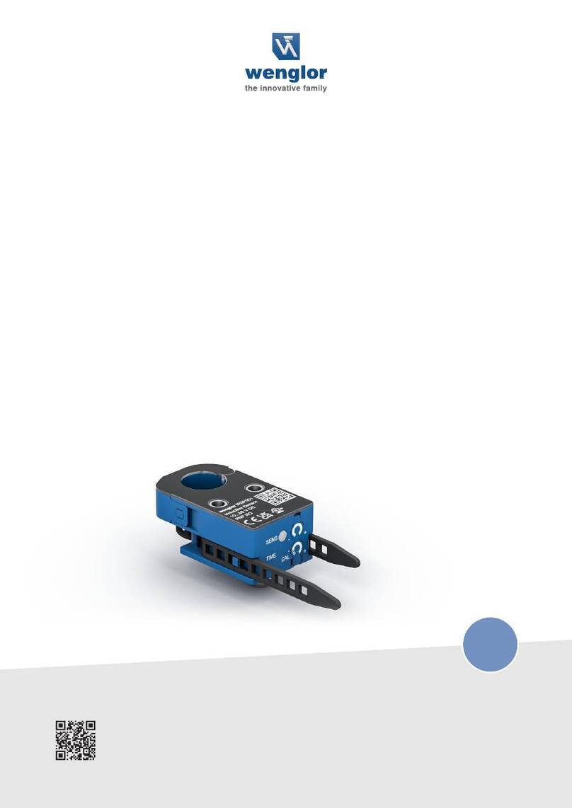
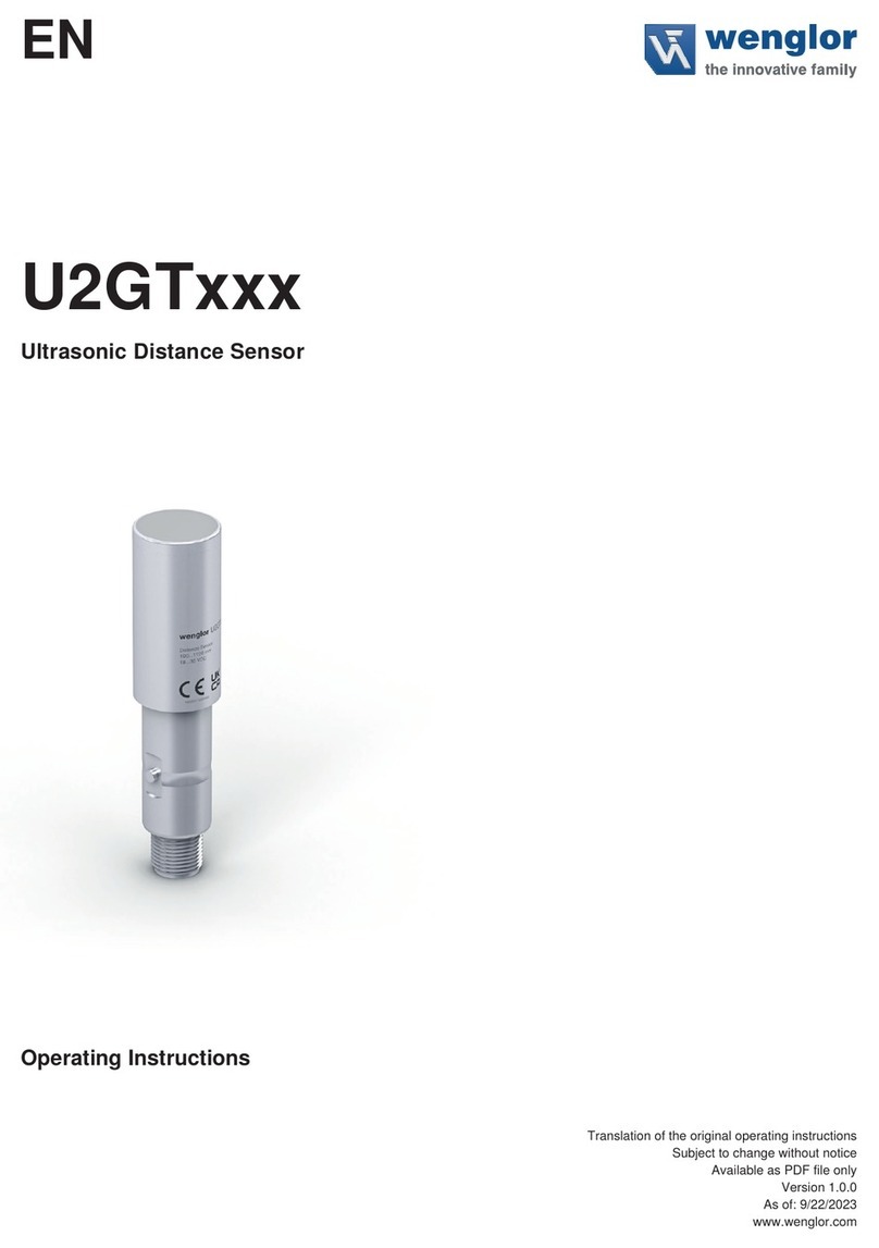
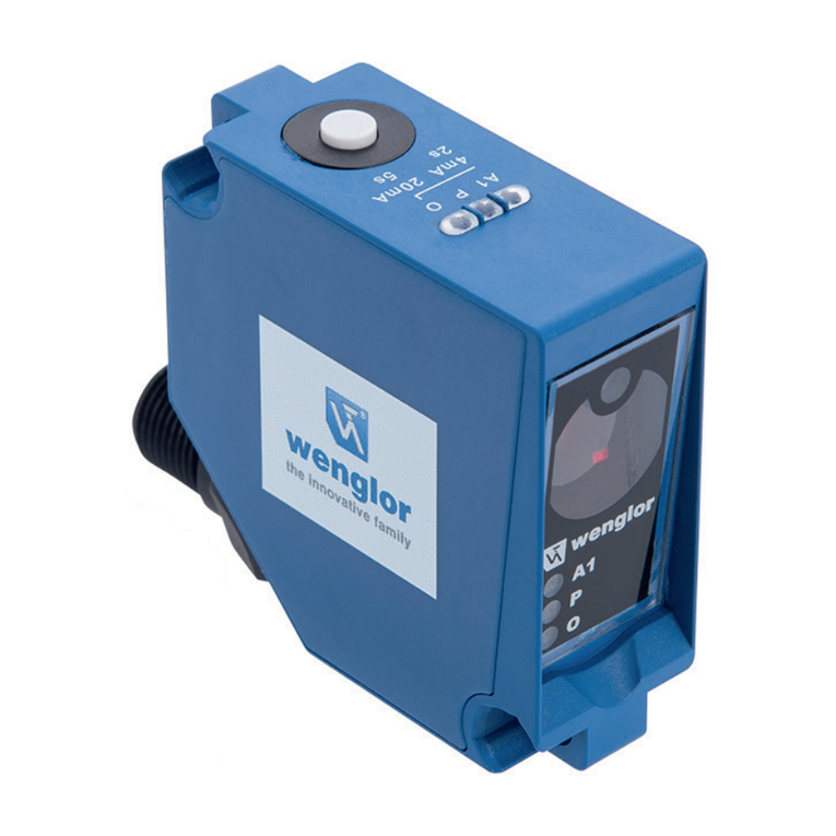
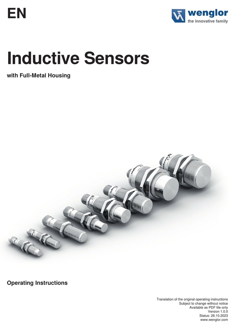
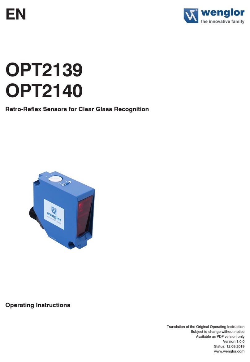
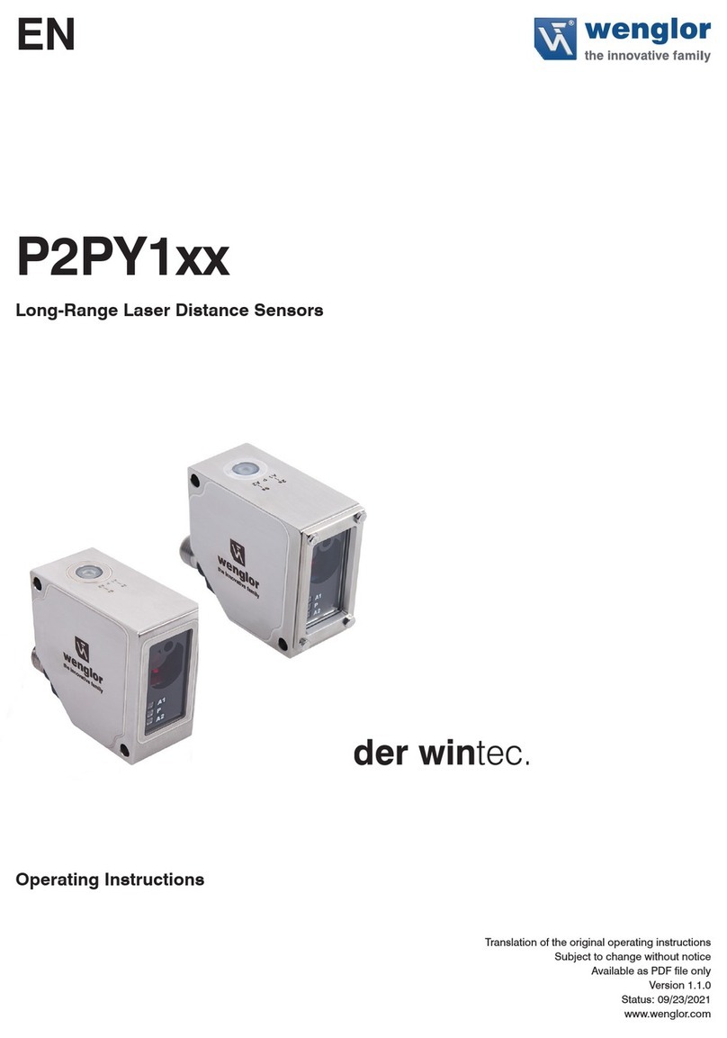
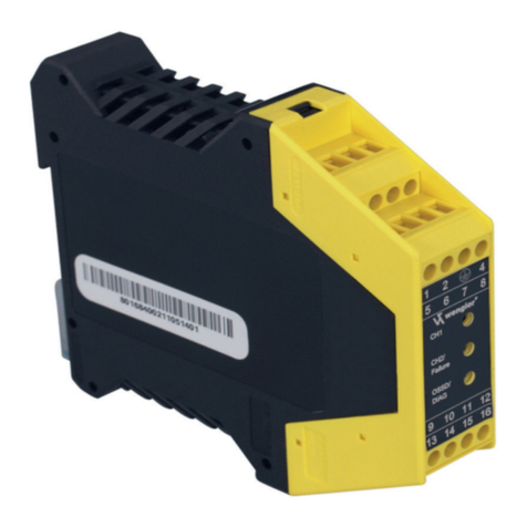
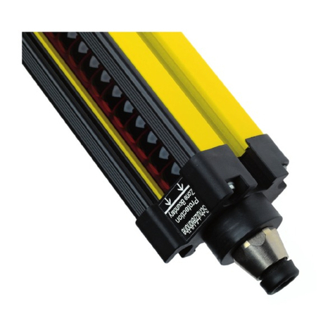
Wenglor PNBC Series User manual

EN
PNBCxxx
Laser Distance Sensors High-Precision
Operating Instructions
Available as PDF file only
Status: 23.08.2022
Version: 1.5.2
www.wenglor.com

2
EN
Table of Contents
1. Change Index, Operating Instructions .....................................................................................................6
2. General ........................................................................................................................................................7
2.1 Information Concerning these Instructions ..........................................................................................7
2.2 Explanations of Symbols......................................................................................................................7
2.3 Limitation of Liability.............................................................................................................................8
2.4 Copyrights............................................................................................................................................8
3. For Your Safety ...........................................................................................................................................9
3.1 Use for Intended Purpose....................................................................................................................9
3.2 Use for Other than the Intended Purpose............................................................................................9
3.3 Personnel Qualifications .....................................................................................................................9
3.4 Modification of Products.......................................................................................................................9
3.5 General Safety Precautions...............................................................................................................10
3.6 Laser/LED Warnings..........................................................................................................................10
3.6.1 Warnings According to Standard EN 60825-1:2007 ..............................................................10
3.6.2 Warnings According to Standard EN 60825-1:2014 ..............................................................11
3.7 Approvals and protection class..........................................................................................................11
4. Technical Data ..........................................................................................................................................12
4.1 Measuring rate...................................................................................................................................14
4.2 Wiring Diagram .................................................................................................................................15
4.3 Housing Dimensions..........................................................................................................................16
4.4 Control Panel .....................................................................................................................................18
4.5 Complementary Products ..................................................................................................................18
5. System Overview......................................................................................................................................19
6. Installation Instructions ...........................................................................................................................20
6.1 Default Settings..................................................................................................................................21
7. Initial Start-Up ...........................................................................................................................................21
8. Function Descriptions..............................................................................................................................22
8.1 Evaluation method .............................................................................................................................23
8.1.1 Center of Gravity (Cog) ..........................................................................................................23

3
High-Performance Distance Sensors
8.1.2 Edge Evaluation .....................................................................................................................23
8.2 Measuring Accuracy and Error Influence...........................................................................................24
8.2.1 Calibration Report ..................................................................................................................24
8.2.2 Surface Material .....................................................................................................................25
8.2.3 Surface Damage on the Object to be Measured ....................................................................25
8.2.4 Extraneous Light ....................................................................................................................25
8.2.5 Changes in Remission ...........................................................................................................25
8.2.6 Dependence of Measurement on Angle.................................................................................25
9. Settings ....................................................................................................................................................26
9.1 Page Layout (website) .......................................................................................................................28
9.2 Device Settings (website) ..................................................................................................................30
9.3 I/O Settings (website).........................................................................................................................31
10. Interface Protocol .....................................................................................................................................35
10.1 General Measuring Commands.........................................................................................................35
10.1.1 Selecting the “Continuous Distance Measurement” Data Format ..........................................35
10.1.2 Selecting the “Extended Continuous Measurement” Data Format.........................................35
10.1.3 Selecting the Data Format for Peak Data...............................................................................35
10.1.4 Stopping the Measurement ....................................................................................................35
10.1.5 Reply Mode ............................................................................................................................35
10.2 Sensor Settings..................................................................................................................................36
10.2.1 Setting the IP Address............................................................................................................36
10.2.2 Setting the Subnet Mask Address ..........................................................................................36
10.2.3 Setting the Gateway Address.................................................................................................36
10.2.4 Reset the Network Settings to Default Values .......................................................................36
10.2.5 Select the Evaluation Method.................................................................................................36
10.2.6 Adjusting the Average Filter ...................................................................................................37
10.2.7 Setting the Output Rate..........................................................................................................37
10.2.8 Setting the Sampling Rate......................................................................................................37
10.2.9 Setting Regulation of Laser Power and the Sampling Rate ...................................................38
10.2.10 Protective Screen Compensation...........................................................................................38
10.2.11 Setting Laser Power ...............................................................................................................38
10.2.12 Adjusting Offset ......................................................................................................................38
10.2.13 Encoder Reset........................................................................................................................39
10.2.14 Encoder Counter Right Shift...................................................................................................39
10.2.15 Switching the Laser On/Off ....................................................................................................39
10.2.16 Reset to Default Values..........................................................................................................39

4
EN
10.3 I/O Settings ........................................................................................................................................40
10.3.1 Selecting the Analog Mode ....................................................................................................40
10.3.2 Setting the Pin Function .........................................................................................................40
10.3.3 Selecting the Output Mode.....................................................................................................40
10.3.4 Setting the Output Function....................................................................................................41
10.3.5 Teaching the Switching Distance (Teach-in) ..........................................................................41
10.3.6 Selecting the Teach-In Mode .................................................................................................41
10.3.7 Setting the Switching Point.....................................................................................................42
10.3.8 Setting Hysteresis ..................................................................................................................42
10.3.9 Setting Switching Reserve .....................................................................................................43
10.3.10 Setting Window Width ............................................................................................................43
10.3.11 Setting Input Load ..................................................................................................................43
10.3.12 Setting the Input Function ......................................................................................................44
10.3.13 Setting Packet Length ............................................................................................................44
10.4 Query Commands..............................................................................................................................45
10.4.1 Querying the IP Address ........................................................................................................45
10.4.2 Querying the Subnet Mask Address.......................................................................................45
10.4.3 Querying the Gateway Address .............................................................................................45
10.4.4 Querying the MAC Address....................................................................................................45
10.4.5 Querying the Hardware Version .............................................................................................45
10.4.6 Querying the Description ........................................................................................................45
10.4.7 Querying the Manufacturer.....................................................................................................46
10.4.8 Querying the Order Number ...................................................................................................46
10.4.9 Querying the Serial Number ...................................................................................................46
10.4.10 Querying the Product Version ................................................................................................46
10.4.11 Querying the Setting for the Evaluation Mode........................................................................46
10.4.12 Querying the Average Filter ...................................................................................................46
10.4.13 Quering the Output Rate ........................................................................................................47
10.4.14 Quering the Sampling Rate ....................................................................................................47
10.4.15 Quering Regulation of Laser Power and the Sampling Rate..................................................47
10.4.16 Quering Laser Power .............................................................................................................47
10.4.17 Quering the Encoder Right Shift Setting ................................................................................48
10.4.18 Quering the Analog Mode ......................................................................................................48
10.4.19 Quering the Pin Function........................................................................................................48
10.4.20 Quering the Output Mode.......................................................................................................49
10.4.21 Quering the Output Function ..................................................................................................49
10.4.22 Quering Switching Distance ...................................................................................................49

5
High-Performance Distance Sensors
10.4.23 Quering the Teach-in Mode....................................................................................................49
10.4.24 Quering Hysteresis .................................................................................................................50
10.4.25 Quering Switching Reserve ....................................................................................................50
10.4.26 Quering Window Width...........................................................................................................50
10.4.27 Quering Input Load.................................................................................................................50
10.4.28 Quering the Input Function.....................................................................................................51
10.4.29 Quering the Input Status ........................................................................................................51
10.4.30 Quering the Input/Output Status of All Inputs/Outputs ...........................................................51
10.4.31 Quering Packet Length...........................................................................................................51
10.5 Header and Data Format ...................................................................................................................52
10.5.1 Continuous Distance Measurement .......................................................................................53
10.5.2 Extended Continuous Measurement (Distance, Intensity, Encoder)......................................54
10.5.3 Peak Data...............................................................................................................................55
10.5.4 Description of the Measurement Data....................................................................................56
11. Maintenance Instructions ........................................................................................................................58
12. Proper Disposal ........................................................................................................................................58
13. EU Declaration of Conformity..................................................................................................................58

6
EN
Change Index, Operating Instructions
1. Change Index, Operating Instructions
Version Date Description/Change Associated product, hardware
and firmware versions
1.0.0 26.03.2017 Initial version of the operating instructions PNBC product version: 1.0.0
PNBC hardware version: 3.3.0
PNBC firmware version: 3.30.6
1.1.0 05.07.2017 • Expansion: measuring rate table
• Expansion: Ethernet wiring diagram
• Update: symbols explanation
• Update: supplementary products
• Expansion: system overview
• Expansion: “compensation when using
screening grids”
• Update: calibration report
• Update: website
PNBC product version: B / 1.30
PNBC hardware version: 3.4.0
PNBC firmware version: 3.50.1
1.2.0 24.09.2019 • Laser warnings (EN 60825-1:2014) PNBC product version: B / 1.30
PNBC hardware version: 3.4.0
PNBC firmware version: 3.50.1
1.2.1 29.09.2020 • Addition to analog output (see section 9.3)
• Adaption of supply voltage
PNBC product version: B / 1.30
PNBC hardware version: 3.5.0
PNBC firmware version: 3.50.6
1.3.0 18.05.2021 • Implementation of PNBC Interface Protocol
• Extension Error Output
PNBC product version: C
PNBC hardware version: 3.5.0
PNBC firmware version: 3.50.8
1.4.0 21.07.2021 • Adaption data format PNBC product version: C
PNBC hardware version: 3.5.0
PNBC firmware version: 3.50.8
1.4.1 08.12.2021 • Adaption of general information of operating
instructions
PNBC product version: C
PNBC hardware version: 3.5.0
PNBC firmware version: 3.50.8
1.5.0 15.06.2022 • Added data in section 4 PNBC product version: C
PNBC hardware version: 3.5.0
PNBC firmware version: 3.50.8
1.5.1 01.08.2022 • Update of legend in section 4.2 PNBC product version: C
PNBC hardware version: 3.5.0
PNBC firmware version: 3.50.8
1.5.2 23.08.2022 • Adaption Laser Warnings (see section 3.6) PNBC product version: C
PNBC hardware version: 3.5.0
PNBC firmware version: 3.50.8

7
High-Performance Distance Sensors
2. General
2.1 Information Concerning these Instructions
• These instructions enable safe and efficient use of the following products:
»PNBCxxx
• These instructions are an integral part of the product and must be kept on hand for the entire duration of its
service life.
• Local accident prevention regulations and national work safety regulations must be complied with as well.
• The product is subject to further technical development, and thus the information contained in these
operating instructions may also be subject to change. The current version can be found at
www.wenglor.com in the product’s separate download area.
NOTE!
The operating instructions must be read carefully before using the product and must be kept
on hand for later reference.
2.2 Explanations of Symbols
• Safety precautions and warnings are emphasized by means of symbols and attention-getting words.
• Safe use of the product is only possible if these safety precautions and warnings are adhered to.
The safety precautions and warnings are laid out in accordance with the following principle:
ATTENTION-GETTING WORD
Type and Source of Danger!
Possible consequences in the event that the hazard is disregarded.
• Measures for averting the hazard.
The meanings of the attention-getting words, as well as the scope of the associated hazards, are listed below.
DANGER!
This word indicates a hazard with a high degree of risk which, if not avoided, results in death
or severe injury.
WARNING!
This word indicates a hazard with a medium degree of risk which, if not avoided, may result
in death or severe injury.
CAUTION!
This word indicates a hazard with a low degree of risk which, if not avoided, may result in
minor or moderate injury.
ATTENTION:
This word draws attention to a potentially hazardous situation which, if not avoided, may
result in property damage.
NOTE!
A note draws attention to useful tips and suggestions, as well as information regarding ef-
ficient, error-free use.

8
EN
General
2.3 Limitation of Liability
• The product has been developed taking into account the state of the art as well as the applicable standards
and guidelines.
• We reserve the right to make technical changes.
• A valid declaration of conformity can be found at www.wenglor.com in the download area of the product.
• wenglor sensoric elektronische Geräte GmbH (hereinafter "wenglor") accepts no liability for:
»failure to observe the operating manual,
»unsuitable or improper use of the product,
»excessive use, incorrect or negligent treatment of the product,
»incorrect installation or commissioning,
»use of untrained personnel,
»use of unauthorized spare parts or
»Improper or unauthorized changes, modifications or repair work to the products.
• This operating manual does not contain any guarantees/warrantees from wenglor with regard to the pro-
cesses described or certain product properties.
• wenglor assumes no liability with regard to printing errors or other inaccuracies contained in this operating
manual, unless it can be proven that wenglor was aware of the errors at the time the operating manual was
created.
2.4 Copyrights
• The contents of these instructions are protected by copyright law.
• All rights are reserved by wenglor.
• Commercial reproduction or any other commercial use of the provided content and information, in particular
graphics and images, is not permitted without previous written consent from wenglor.

9
High-Performance Distance Sensors
3. For Your Safety
3.1 Use for Intended Purpose
This wenglor product is intended for use in accordance with the following functional principle:
Laser Distance Sensor High-Precision
This product group includes Laser Distance Sensors High-Precision for measuring distance, which function in
accordance with various principles in scanning mode operation. Laser Distance Sensors High-Precision are
especially fast or accurate, or have large working ranges. They’re extremely well suited for demanding applica-
tions. Even black and glossy objects can be reliably detected. Ethernet technology is integrated into selected
sensors.
3.2 Use for Other than the Intended Purpose
• The product is not a safety component in accordance with the EG Machinery Directive.
• The product is not suitable for use in potentially explosive atmospheres.
DANGER!
Risk of personal injury or property damage in case of use for other than the
intended purpose!
Use for other than the intended purpose may lead to hazardous situations.
• Instructions regarding use for intended purpose must be observed.
3.3 Personnel Qualications
• Suitable technical training is a prerequisite.
• In-house electronics training is required.
• Trained personnel who use the product must have uninterrupted access to the operating instructions.
• Valid laser protection requirements must always be adhered to.
Attention!
Risk of personal injury or property damage in case of incorrect initial start-up
and maintenance!
Personal injury and damage to equipment may occur.
• Adequate training and qualification of personnel.
3.4 Modication of Products
Attention!
Risk of personal injury or property damage if the product is modied!
Personal injury and damage to equipment may occur. Non-observance may result in
loss of the CE marking and the guarantee may be rendered null and void.
• Modification of the product is impermissible.

10
EN
For Your Safety
3.5 General Safety Precautions
NOTE!
• These instructions are an integral part of the product and must be kept on hand for the
entire duration of its service life.
• In the event of possible changes, the respectively current version of the operating
instructions can be accessed at www.wenglor.com in the product’s separate download
area.
• Read the operating instructions carefully before using the product.
• The sensor must be protected against contamination and mechanical influences.
3.6 Laser/LED Warnings
LASER CLASS 2
EN60825-1
Laser Class 2 (EN 60825-1)
Observe all applicable standards and safety precautions.
The enclosed laser warning lables must be attached and visible at all time.
Do not stare into beam.
Attention!
If other operating or adjustment devices than those specified here are used or other proce-
dures are carried out, this can lead to dangerous exposure to radiation.
3.6.1 Warnings According to Standard EN 60825-1:2007
LASER RADIATION
DO NOT STARE INTO BEAM
Complies with 21 CFR
1040.10 and 1040.11 except
for deviations pursuant to Laser
Notice No. 50, July 2001
CAUTION
LASER RADIATION -
DO NOT STARE INTO BEAM
CAUTION
Conforme aux règlements
21CFR 1040.10 et 1040.11
sauf pour les dérogations selon
l'avis sur les dispositifs
laser n° 50, juillet 2001
LASER RADIATION
DO NOT STARE INTO BEAM
CLASS 2 LASER PRODUCT
EN60825-1: 2007
Po<1mW, λ= 620-690 nm
LASERSTRAHLUNG
NICHT IN DEN STRAHL BLICKEN
LASER KLASSE 2
EN60825-1: 2007
Po<1mW, λ=620 –690nm

11
High-Performance Distance Sensors
3.6.2 Warnings According to Standard EN 60825-1:2014
EN60825-1: 2014
λ= 620-690 nm
LASER
2
LASER RADIATION
DO NOT STARE INTO BEAM
Complies with 21 CFR
1040.10 and 1040.11 except
for deviations pursuant to Laser
Notice No. 50, June 24, 2007
CLASS 2 LASER PRODUCT
CAUTION
LASER RADIATION -
DO NOT STARE INTO BEAM
CAUTION
Conforme aux règlements
21CFR 1040.10 et 1040.11
sauf pour les dérogations selon
l'avis sur les dispositifs
laser n° 50, juin 24, 2007
CLASS 2 LASER PRODUCT
3.7 Approvals and protection class
IND. CONT. EQ
72HL / E189727
For use in class 2 circuits
NOTE!
Several sensors do not have a UL certification. Please see datasheet of the sensor.

12
EN
Technical Data
4. Technical Data
PNBC001 PNBC002 PNBC003 PNBC004
Optical Characteristics
Working range [mm] 20…24 25…35 40 to 60 58 to 108
Measuring range 4 mm 10 mm 20 mm 50 mm
Resolution 0.06 µm 0.15 µm 0.3 µm 0.8 µm
Linearity deviation 2 µm 5 µm 10 µm 25 µm
Light source Laser (red) Laser (red) Laser (red) Laser (red)
Wavelength 658 nm 658 nm 658 nm 658 nm
Service life (T = +25° C) 100,000 hours 100,000 hours 100,000 hours 100,000 hours
Laser class (EN 60825-1) 2 2 2 2
Max. ambient light 10,000 lux 10,000 lux 10,000 lux 10,000 lux
Light spot diameter < 0.15 mm < 0.20 mm < 0.25 mm < 0.35 mm
Electrical Characteristics
Supply voltage 15 to 30 V DC 15 to 30 V DC 15 to 30 V DC 15 to 30 V DC
Current consumption (Ub=24V) 280 mA 280 mA 280 mA 280 mA
Switching frequency 15 kHz 15 kHz 15 kHz 15 kHz
Response time <33 µs <33 µs <33 µs <33 µs
Output rate 10...30000/s 10...30000/s 10...30000/s 10...30000/s
Temperature drift 0.2 µm/K 0.5 µm/K 1 µm/K 2.5 µm/K
Temperature range –10 to 40° C –10 to 40° C –10 to 40° C –10 to 40° C
Storage temperature –20 to 70° C –20 to 70° C –20 to 70° C –20 to 70° C
Number of switching outputs 4 4 4 4
Switching output voltage drop < 1.5 V < 1.5 V < 1.5 V < 1.5 V
Switching output/switching
current 100 mA 100 mA 100 mA 100 mA
Switching input low level 0,8...2 V 0,8...2 V 0,8...2 V 0,8...2 V
Switching input high level 1,5...2,5 V 1,5...2,5 V 1,5...2,5 V 1,5...2,5 V
Switching input resistance > 24 kΩ * > 24 kΩ * > 24 kΩ * > 24 kΩ *
Surge strength (EN 60947-1) 1 kV 1 kV 1 kV 1 kV
Switchable to NC/NO Yes Yes Yes Yes
Configurable to PNP / NPN /
push-pull Yes Yes Yes Yes
Analog output 0...10 V/4...20 mA 0...10 V/4...20 mA 0...10 V/4...20 mA 0...10 V/4...20 mA
Short-circuit protection Yes Yes Yes Yes
Reverse polarity protection Yes Yes Yes Yes
Overload protection Yes Yes Yes Yes
Teach-in-Modus VT/FT VT/FT VT/FT VT/FT
Interface Ethernet TCP/IP Ethernet TCP/IP Ethernet TCP/IP Ethernet TCP/IP
Baud rate 100 Mbit/s 100 Mbit/s 100 Mbit/s 100 Mbit/s
Protection class III III III III
Webserver Yes Yes Yes Yes

13
High-Performance Distance Sensors
PNBC001 PNBC002 PNBC003 PNBC004
Mechanical Characteristics
Setting method Teach-in Teach-in Teach-in Teach-in
Housing material Aluminum Aluminum Aluminum Aluminum
Degree of protection IP 67 IP 67 IP 67 IP 67
Connection M12×1, 8-pin M12×1, 8-pin M12×1, 8-pin M12×1, 8-pin
Type of connection Ethernet M12× 1, 4-pin M12×1, 4-pin M12×1, 4-pin M12×1, 4-pin
Optic cover Glass Glass Glass Glass
* only valid if input load is switched off
PNBC005 PNBC006 PNBC007 PNBC008
Optical Characteristics
Working range [mm] 90…190 200…400 250…650 200…1000
Measuring range 100 mm 200 mm 400 mm 800 mm
Resolution 1.5 µm 3.1 µm 6.1 µm 12.2 µm
Linearity deviation 50 µm 100 µm 200 µm 375 µm
Light source Laser (red) Laser (red) Laser (red) Laser (red)
Wavelength 658 nm 658 nm 658 nm 658 nm
Service life (T = +25° C) 100,000 hours 100,000 hours 100,000 hours 100,000 hours
Laser class (EN 60825-1) 2 2 2 2
Max. ambient light 10,000 lux 10,000 lux 10,000 lux 10,000 lux
Light spot diameter < 0.75 mm < 0.90 mm < 1.20 mm < 1.60 mm
Electrical Characteristics
Supply voltage 15 to 30 V DC 15 to 30 V DC 15 to 30 V DC 15 to 30 V DC
Current consumption (Ub=24V) 280 mA 280 mA 280 mA 280 mA
Switching frequency 15 kHz 15 kHz 15 kHz 15 kHz
Response time <33 µs <33 µs <33 µs <33 µs
Output rate 10...30000/s 10...30000/s 10...30000/s 10...30000/s
Temperature drift 5 µm/K 10 µm/K 20 µm/K 37.5 µm/K
Temperature range –10 to 40° C –10 to 40° C –10 to 40° C –10 to 40° C
Storage temperature –20 to 70° C –20 to 70° C –20 to 70° C –20 to 70° C
Number of switching outputs 4 4 4 4
Switching output voltage drop < 1.5 V < 1.5 V < 1.5 V < 1.5 V
Switching output/switching
current 100 mA 100 mA 100 mA 100 mA
Switching input low level 0,8...2 V 0,8...2 V 0,8...2 V 0,8...2 V
Switching input high level 1,5...2,5 V 1,5...2,5 V 1,5...2,5 V 1,5...2,5 V
Switching input resistance > 24 kΩ * > 24 kΩ * > 24 kΩ * > 24 kΩ *
Surge strength (EN 60947-1) 1 kV 1 kV 1 kV 1 kV
Switchable to NC/NO Yes Yes Yes Yes
Configurable to PNP / NPN /
push-pull Yes Yes Yes Yes

14
EN
Technical Data
PNBC005 PNBC006 PNBC007 PNBC008
Analog output 0...10 V/4...20 mA 0...10 V/4...20 mA 0...10 V/4...20 mA 0...10 V/4...20 mA
Short-circuit protection Yes Yes Yes Yes
Reverse polarity protection Yes Yes Yes Yes
Overload protection Yes Yes Yes Yes
Teach-in-Modus VT/FT VT/FT VT/FT VT/FT
Interface Ethernet TCP/IP Ethernet TCP/IP Ethernet TCP/IP Ethernet TCP/IP
Baud rate 100 Mbit/s 100 Mbit/s 100 Mbit/s 100 Mbit/s
Protection class III III III III
Webserver Yes Yes Yes Yes
Mechanical Characteristics
Setting method Teach-in Teach-in Teach-in Teach-in
Housing material Aluminum Aluminum Aluminum Aluminum
Degree of protection IP67 IP67 IP67 IP67
Connection M12×1, 8-pin M12×1, 8-pin M12×1, 8-pin M12×1, 8-pin
Type of connection Ethernet M12×1, 4-pin M12×1, 4-pin M12×1, 4-pin M12×1, 4-pin
Optic cover Glass Glass Glass Glass
* only valid if input load is switched off
4.1 Measuring rate
Determination of the measuring rate on various surfaces with an angle of incidence of 90°
PNBC001 PNBC002 PNBC003 PNBC004
Object color
white 30 kHz 30 kHz 30 kHz 30 kHz
gray 30 kHz 30 kHz 30 kHz 30 kHz
black 1 kHz 27 kHz 27 kHz 12 kHz
PNBC005 PNBC006 PNBC007 PNBC008
Object color
white 30 kHz 30 kHz 25 kHz 25 kHz
gray 30 kHz 30 kHz 20 kHz 18 kHz
black 12 kHz 10 kHz 6 kHz 5 kHz
Values measured on OPTEKA Digital Color & White Balance Grey Card Set
Degree of remission: white: 90%
gray: 18%
black: 6%
NOTE!
These are typical measured values which may vary depending
on surface characteristics and angle of incidence.

15
High-Performance Distance Sensors
4.2 Wiring Diagram
Legend
+Supply Voltage + nc Not connected ENBRS422 Encoder B/ (TTL)
–Supply Voltage 0 V UTest Input ENAEncoder A
~Supply Voltage (AC Voltage) Test Input inverted ENBEncoder B
ASwitching Output (NO) WTrigger Input AMIN Digital output MIN
ĀSwitching Output (NC) W– Ground for the Trigger Input AMAX Digital output MAX
VContamination/Error Output (NO) OAnalog Output AOK Digital output OK
Contamination/Error Output (NC) O– Ground for the Analog Output SY In Synchronization In
EInput (analog or digital) BZ Block Discharge SY OUT Synchronization OUT
TTeach Input AMV Valve Output OLT Brightness output
ZTime Delay (activation) a Valve Control Output + M Maintenance
SShielding b Valve Control Output 0 V rsv Reserved
RxD Interface Receive Path SY Synchronization Wire Colors according to DIN IEC 60757
TxD Interface Send Path SY– Ground for the Synchronization BK Black
RDY Ready E+ Receiver-Line BN Brown
GND Ground S+ Emitter-Line RD Red
CL Clock Grounding OG Orange
E/A Output/Input programmable SnR Switching Distance Reduction YE Yellow
Rx+/– Ethernet Receive Path GN Green
PoE ower over Ethernet Tx+/– Ethernet Send Path BU Blue
IN Safety Input BUS Interfaces-Bus A(+)/B(–) VT Violet
OSSD Safety Output La Emitted Light disengageable GY Grey
Signal Signal Output Mag Magnet activation WH White
BI_ D+/– Ethernet Gigabit bidirect. data line (A-D) RES Input conrmation PK Pink
EN0 RS422 Encoder 0-pulse 0/ (TTL) EDM Contactor Monitoring GNYE Green/Yellow
PT Platinum measuring resistor ENA
RS422
Encoder A/Ā (TTL)

16
EN
Technical Data
4.3 Housing Dimensions
PNBC001
1 = Emitter Diode
2 = Receiving Diode
3 = Bearing Surface with M4
on Both Sides
PNBC002
1 = Emitter Diode
2 = Receiving Diode
3 = Bearing Surface with M4
on Both Sides
PNBC003
1 = Emitter Diode
2 = Receiving Diode
3 = Bearing Surface with M4
on Both Sides

17
High-Performance Distance Sensors
PNBC004
1 = Emitter Diode
2 = Receiving Diode
3 = Bearing Surface with M4
on Both Sides
PNBC005
1 = Emitter Diode
2 = Receiving Diode
3 = Bearing Surface with M4
on Both Sides
PNBC006/007/008
1 = Emitter Diode
2 = Receiving Diode
3 = M4 on both sides

18
EN
Technical Data
4.4 Control Panel
68 = Supply Power Indicator
83 = Signal
85 = Link/Act LED
Designation Status Function
Power Green Operating voltage on
Off Operating voltage off
Signal
Green Signal strength OK, sensor ready to measure
Blinking green Weak signal, unreliable measurement results
Red No signal, sensor contaminated and/or overranging
Link/Act Yellow Links available
Blinking yellow Communication
4.5 Complementary Products
wenglor offers Connection Technology for field wiring.
Suitable mounting technology no.
341
Suitable connection technology no.
89
51
Switch ZAC51xN01
Cooling unit
Screening Grid Retainer
Screening Grids
Software wTeach2 DNNF005

19
High-Performance Distance Sensors
5. System Overview
Protective Window Set
Available in glass or plastic
for each protective window holder Legend
Required Accessories
Optional Accessories
Connection Cable
M12, 4-pin to RJ45
ZAV51R202 2 m
ZAV51R602 10 m
M12, 4-polig
ZAV51R201 2 m
ZAV51R601 10 m
Connector Cables
M12, 8-pin to open end
ZAS89R201 2 m
ZAS89R501 5 m
ZAS89R601 10 m
ZAS89R701 20 m
ZAS89R202 (angled)
2 m
ZAS89R502 (angled)
5 m
ZAS89R602 (angled)
10 m
Connection Cable
M12, 8-pin
BG88SG88V2-06M 0,6 m
BG88SG88V2-2M 2 m
Protective Window Holder
Available for each model
Mounting System
ZNBZ001
ZNBZ002
Cooling Module
ZNBK001
ZNBK002
System overview
PNBC004
Photoelectronic Sensors

20
EN
Installation Instructions
6. Installation Instructions
During use of the sensor, applicable electrical and mechanical regulations, standards and safety precautions
must be adhered to. The sensor must be protected against mechanical influences.
When installing the sensor it must be ensured that direct eye contact with the laser beam is avoided. The laser
warning must be plainly visible.
When installing the sensor it must be ensured that the measuring beam is exactly perpendicular to the surface
to be measured in order to assure accurate measurement results. Tilting results in a geometrically longer
measuring path.
Moving or Striped Objects
If moving or striped objects will be measured, the sensor head should be mounted with its long side perpendi-
cular to the motion of direction or the stripes. In this way, better measurement results can be achieved in the
corners because shadowing is avoided:
falsch
wrong
richtig
correct
Other manuals for PNBC Series
1
This manual suits for next models
8
Table of contents
Other Wenglor Security Sensor manuals

Wenglor
Wenglor B60 Series User manual

Wenglor
Wenglor Y1TA Series User manual

Wenglor
Wenglor SG4-I User manual

Wenglor
Wenglor IR2D002 User manual

Wenglor
Wenglor P1MH Series User manual

Wenglor
Wenglor P1KK008 User manual

Wenglor
Wenglor P1PY1 Series User manual

Wenglor
Wenglor SS2-00VA000R2 User manual

Wenglor
Wenglor IR3F001 User manual

Wenglor
Wenglor I08G003 User manual