Detcon MicroSafe TP-524C User manual
detcon inc.
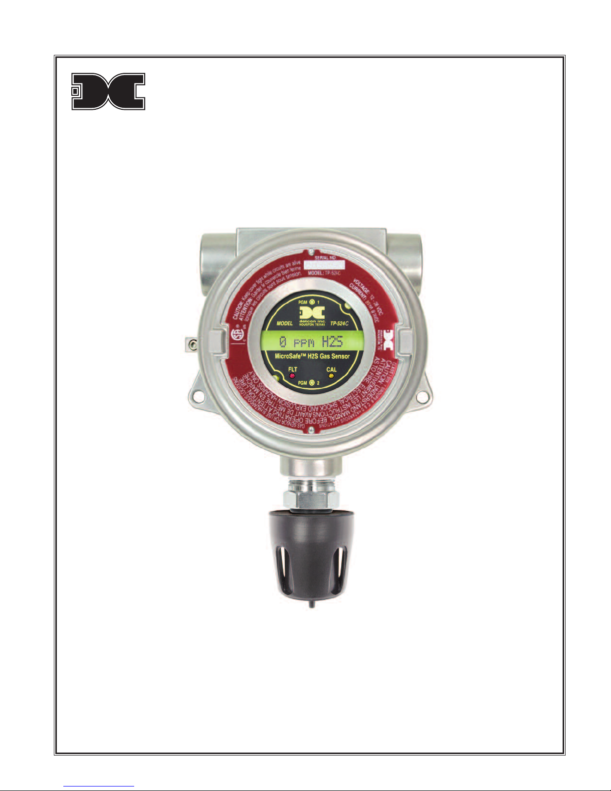
Detcon MicroSafe™
TP-524C Hyd ogen Sulfide Senso
Th s manual covers the follow ng ranges: 0-20 PPM, 0-50 PPM, and 0-100 PPM
Operator’s Installation & Instruction Manual
May 09, 2012 • Document #2297 • Vers on 2.5

Table of Content
3.0 Desc iption
3.1 P inciple of Ope ation
3.2 Application
3.3 Specifications
3.4 Ope ating Softwa e
3.5 Installation
3.6 Sta t-up
3.7 Calib ation
3.8
Status of P og amming: Softwa e Ve sion, Calib ation Level, Heate Voltage, Range, and Senso Life
3.9 P og am Featu es
3.10 Display Cont ast Adjust
3.11 T ouble Shooting Guide
3.12 Spa e Pa ts List
3.13 Wa anty
3.14 Se vice Policy
3.15 Softwa e Flow Cha t
3.16 Revision Log
Detcon Model TP-524C Hydrogen Sulfide Sensor
PG.2
3.0 DESCRIPTION
Detcon M croSafe™ Model TP-524C, hydrogen sulf de sensors are non- ntrus ve “Smart” sensors des gned to detect
and mon tor H2S n a r. Ranges of detect on are 0-20 ppm, 0-50 ppm, and 0-100 ppm. One of the pr mary features
of the sensor s ts method of automat c cal brat on wh ch gu des the user through each step v a nstruct ons d s-
played on the backl t LCD. The sensor features LED nd cators for FAULT and CAL status and s equ pped w th a
standard analog 4-20 mA output. The m croprocessor superv sed electron cs are packaged as a plug- n module that
mates to a standard connector board. Both are housed n an explos on proof condulet that ncludes a glass lens. A
16 character alpha/numer c nd cator s used to d splay sensor read ngs as well as the sensor’s menu dr ven features
v a a hand-held programm ng magnet.
3.0.1 Se sor Tech ology
The sensor technology s a patented sol d state metal ox de sem conductor. The sensor cons sts of two th n f lms; a
temperature sens t ve heater f lm, and an hydrogen sulf de sens t ve sensor f lm. Both f lms are depos ted on a s l -
con m croch p by vacuum depos t on. The heater f lm elevates the operat ng temperature of the sensor f lm to a
level where a good sens t v ty and response to hydrogen sulf de s ach eved. The sensor f lm s a propr etary metal
ox de that shows a dynam c response to hydrogen sulf de gas. Range of sens t v ty s from part per b ll on to % by
volume. The rugged sensor s capable of ma nta n ng ts operat ng character st cs for per ods of up to 7-10 years n
most ndustr al env ronments and as such, s supported by a 10-year cond t onal warranty.
Detcon Model TP-524C Hydrogen Sulfide Sensor
PG.
Construction of
Semiconductor Sensor
Sensor
Film
Heater
Film
Silicon
Microchip
3.0.2 Microprocessor Co trol Circuit
The control c rcu t s m croprocessor based and s packaged as a plug- n f eld replaceable module, fac l tat ng easy
replacement and m n mum down t me. C rcu t funct ons nclude a bas c sensor pre-ampl f er, sensor temperature
control, on-board power suppl es, m croprocessor, back l t alpha numer c d splay, fault and cal brat on status LED
nd cators, magnet c programm ng sw tches, and a l near 4-20 mA DC output.
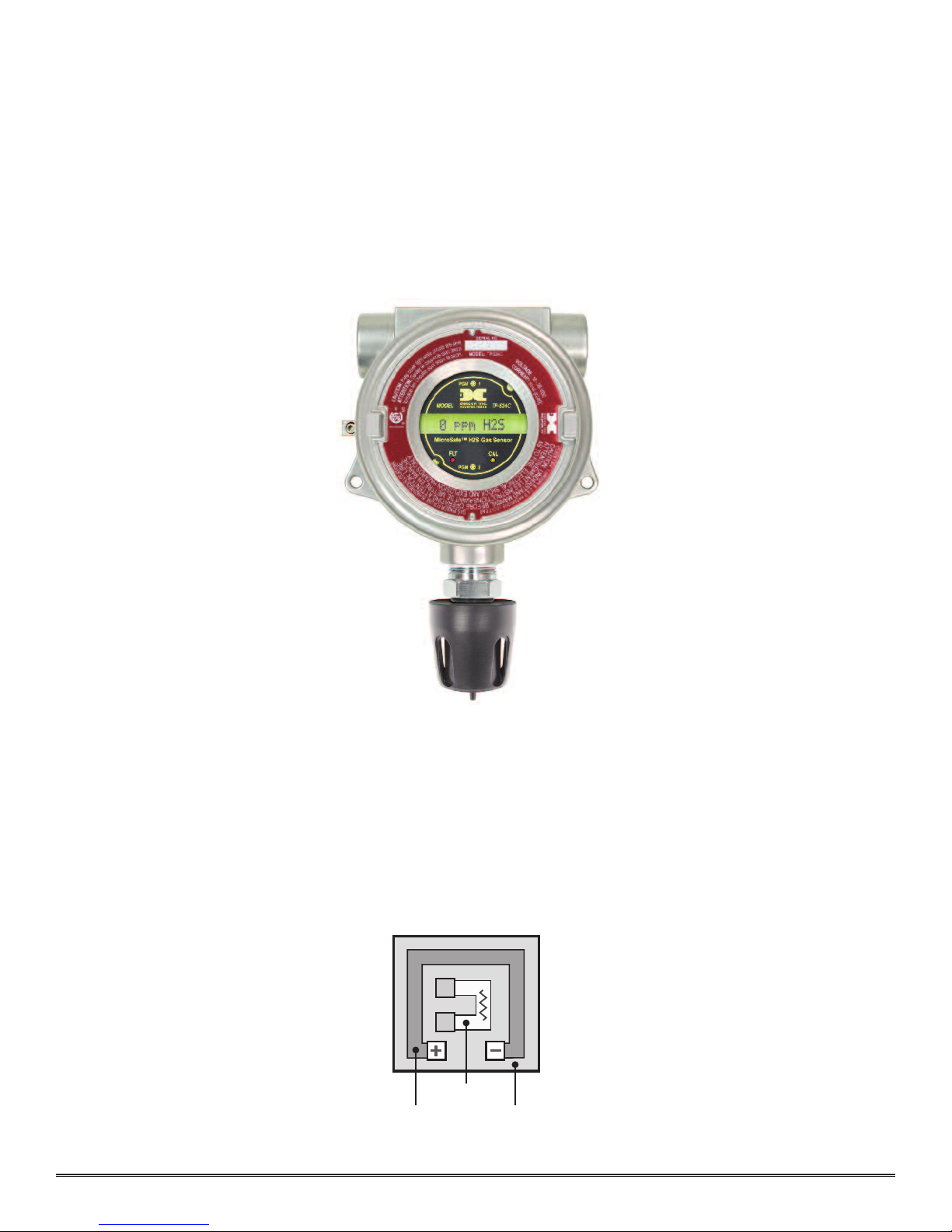
3.0.3 Base Co ector Board
The base connector board s mounted n the explos on proof enclosure and ncludes: the mat ng connector for the
control c rcu t, reverse nput and secondary trans ent suppress on, nput f lter, and lugless term nals for f eld w r ng.
3.0.4 Explosio Proof E closure
Detcon Model TP-524C Hydrogen Sulfide Sensor
PG.4
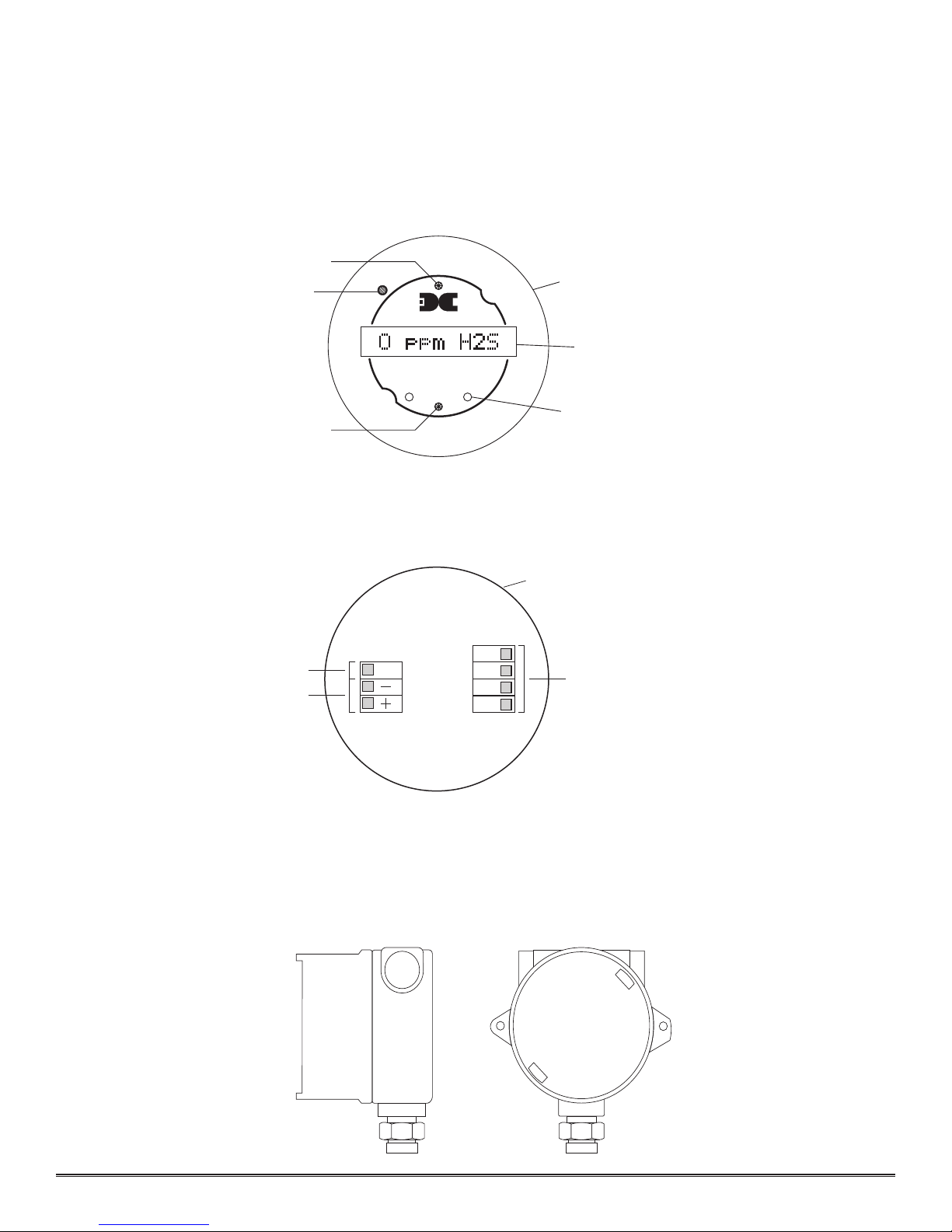
detcon inc.
Program Switch #2
FLT CAL
MicroSafe™ H2S Gas Sensor
HOUSTON, TEXAS
PGM 2
PGM 1
MODEL TP-524C
CONTRAST
Fault & Cal LEDs
Program Switch #1
Menu Driven Display
Plug-in Microprocessor Control Circuit
Display Contrast Adjust
WHT
BLK
YEL
BLU
mA
VDC Power In
4-20 mA Output
Sensor
Base Connector Board
The sensors are packaged n a cast metal explos on-proof enclosure. The enclosure s f tted w th a threaded cover
that has a glass lens w ndow. Magnet c program sw tches located beh nd the transm tter module face plate are act -
vated through the lens w ndow v a a hand-held magnet c programm ng tool allow ng non- ntrus ve operator nter-
face w th the sensor. Cal brat on can be accompl shed w thout remov ng the cover or declass fy ng the area.
Electr cal class f cat on s Class I; Groups B, C, D; D v s on 1 (explos on proof).
3.1 PRINCIPLE OF OPERATION
Method of detect on s by d ffus on/adsorpt on. A r and gas d ffuse through a s ntered sta nless steel f lter and contact
the heated surface of the metal ox de sensor f lm. As hydrogen sulf de gas molecules react w th oxygen ons on the
f lm, there s a decrease n electr cal res stance proport onal to the gas concentrat on. The heater f lm elevates the tem-
perature of the sensor f lm creat ng convect on and promot ng a qu ck response to chang ng gas concentrat ons.
Electron cally, the heater f lm s used to ma nta n a constant temperature of the sensor f lm enhanc ng stab l ty and
repeatab l ty. The sensor response s revers ble and results n cont nuous mon tor ng of amb ent a r cond t ons.
3.2 APPLICATION
Model TP-524C M croSafe™ sensors are des gned to detect and mon tor hydrogen sulf de gas n amb ent a r n the
range of 0-100 parts per m ll on. The sensor can also be programmed to operate n the range 0-20 ppm or 0-50 ppm.
M n mum sens t v ty and scale resolut on s 1 ppm. Operat ng temperature range s --40° F. to +175° F. Wh le the sen-
sor s capable of operat ng outs de these temperatures, performance spec f cat ons are ver f ed w th n the l m t.
3.2.1 Se sor Placeme t/Mou ti g
Sensor locat on should be rev ewed by fac l ty eng neer ng and safety personnel. Area leak sources and per meter
mount ng are typ cally used to determ ne number and locat on of sensors. Hydrogen sulf de gas s sl ghtly heav er
than a r (approx mately 1.18); therefore, the sensors are generally located 2 - 4 feet above grade.
3.2.2 I terfere ce Data
Gas PPM
Methane 25,000 = 0
Ethane 5,000 = 0
Hexane 5,000 = 0
Propane 5,000 = 0
Butane 5,000 = 0
Carbon Monox de 800 = 0
Carbon D ox de 5,000 = 0
Carbon D sulf de 14 = 0
Methanol 200 = 0
Isopropanol 200 = 0
Ammon a 500 = 0
D esel Fuel 1000 = 0
D methyl Sulf de 4.4 = 0
Ethylene 200 = 0
Freon 12 1000 = 0
Hydrogen 5% = 0
Methyl Mercaptan 16 = 6
Sulfur D ox de 300 = 0
Toluene 32 = 0
Ethanol 200 = 0
Detcon Model TP-524C Hydrogen Sulfide Sensor
PG.5
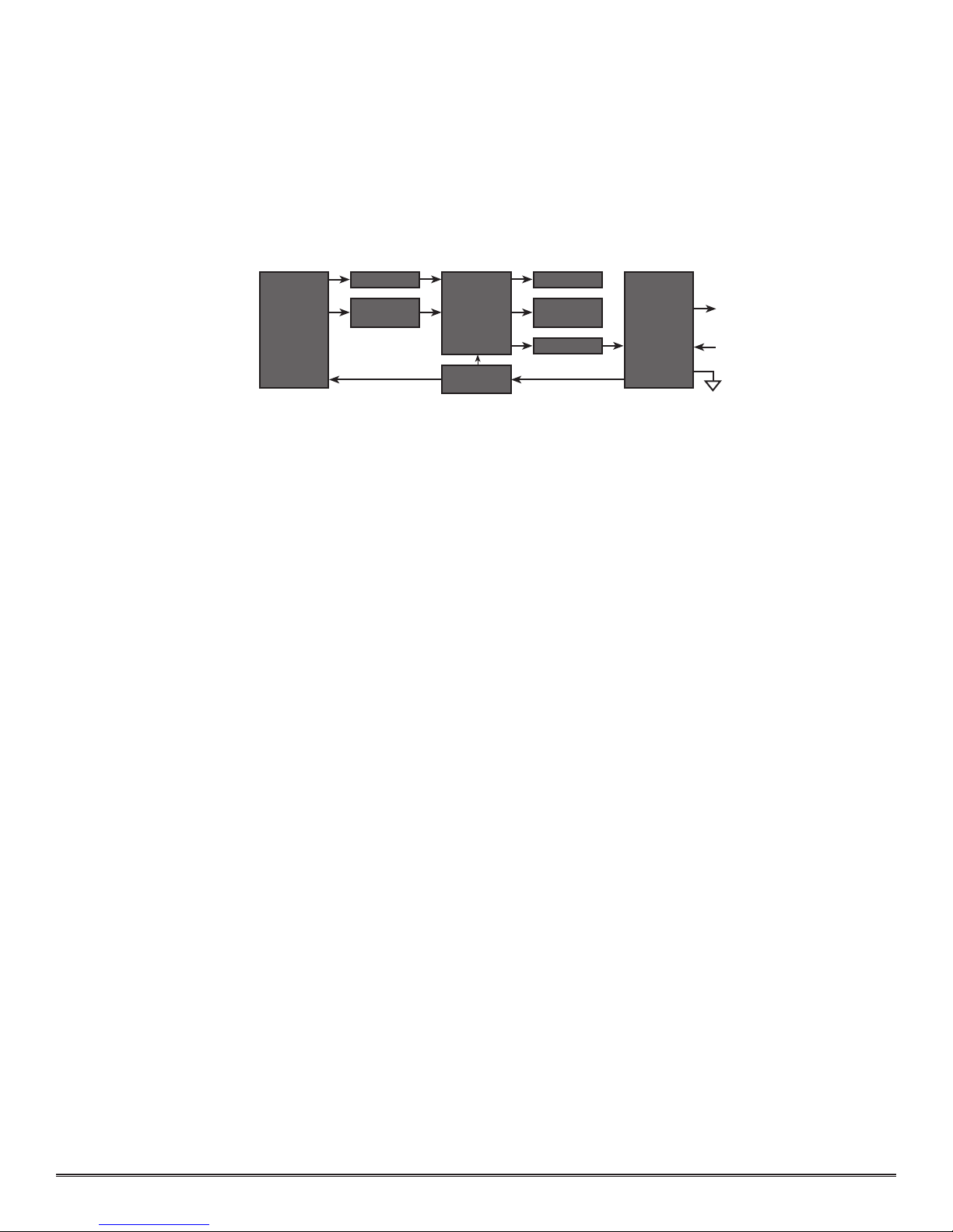
Analog 4-20 mA Out
Functional
Block
Diagram
Power In
Pre-Amp Display
Temperature
Compensation
Cal & Fault
LEDs
4-20mA
Micro-
processor
Transmitter
Power Supply
Sensor
Element
I/O Circuit
Protection

3.3 SPECIFICATIONS
Method of Detection
Sol d state metal ox de d ffus on/adsorpt on
Elect ical Classification
CSA-NRTL (US OSHA) approved Class I; Groups B, C, D; D v. 1.
Response Time
T50 < 30 seconds, T80 < 60 seconds
Clea ing Time
T80 < 30 seconds
Repeatability
± 10% of read ng or ± 2 ppm (greater of)
Range
0-20 ppm, 0-50 ppm, or 0-100 ppm
Ope ating Tempe atu e
-40° to +175° F (-40°C to +75°C)
Accu acy
± 10% of read ng or ± 2 ppm (greater of)
Senso Wa anty
10 year cond t onal
Powe Consumption
Normal operat on = 68 mA (<1.7 watt); Full alarm = 85 mA (2 watts)
Output
L near 4-20 mA DC
Input Voltage
12-28 VDC
3.4 OPERATING SOFTWARE
Operat ng software s menu l sted w th operator nterface v a the two magnet c program sw tches located under the
face plate. The two sw tches are referred to as “PGM 1” and “PGM 2”. The menu l st cons sts of 3 tems wh ch
nclude sub-menus as nd cated below. (Note: see the last page of th s manual for a complete software flow chart.)
01. Normal Operat on
a) Current Status
02. Cal brat on Mode
a) Span
03. Program Menu
a) V ew Program Status
b) Set Cal brat on Level
c) Set Heater Level
d) Set Range
e) Ut l ty Menu
3.4.1 Normal Operatio
In normal operat on, the d splay reflects the current status of the sensor and gas concentrat on and appears as:
“0 PPM H2S”. The mA current output corresponds to the mon tor ng level and range of detect on = 4-20 mA.
3.4.2 Calibratio Mode
Cal brat on mode allows for sensor span adjustments. Unless otherw se spec f ed, span adjustment s performed at
10 ppm H2S n a r for the range 0-20 ppm, and 25 ppm H2S n a r for the ranges 0-50 ppm and 0-100 ppm.
“AUTO SPAN”
Detcon Model TP-524C Hydrogen Sulfide Sensor
PG.6

3.4.3 Program Mode
The program mode prov des a program status menu (V ew Program Status) to check operat onal parameters. It also
allows for the adjustment of the cal brat on gas level sett ng, the heater voltage level, range, and l near ty correct on.
.4. .1 Program Status
The program status scrolls through a menu that d splays:
* The gas type, range of detect on and software vers on number. The menu tem appears as: “H2S 0-100 #.#”
* The cal brat on gas level sett ng. The menu tem appears as: “CalLevel @ ##PPM”
* The sensor heater voltage sett ng. The menu tem appears as: “HEATER @ #.## DC”
* The range of detect on sett ng. The menu tem appears as: “RANGE @ 0-###PPM”
* The est mated rema n ng sensor l fe. The menu tem appears as: “SENSOR LIFE 100%”
* The raw res stance of the sensor f lm. The menu tem appears as “RESISTANCE = XX” ( n ohms)
.4. .2 Set Cal Level Adjustment
The Cal brat on level s adjustable from 10% to 50% of full-scale range. The menu tem appears as: “CalLevel @ ##PPM”
.4. . Set Heater Level Adjustment
The Heater Level s adjustable from 4.40 to 5.40 vdc (normally 5.25). The menu tem appears as: “Heater @ #.## vdc”
.4. .4 Set Range
The full-scale range s adjustable between 0-20 ppm, 0-50 ppm and 0-100 ppm The tem appears as: “Range @ 0-### ppm”
.4. .5 Utility Menu
“Set X Value” s an adjustment for l near zat on (factory sett ng only!)
“Set F lter Mode” s a select on of f lter ng modes (factory sett ng only!)
3.5 INSTALLATION
Opt mum performance of amb ent a r/gas sensor dev ces s d rectly relat ve to proper locat on and nstallat on pract ce.
3.5.1 Field Wiri g Table (4-20 mA output)
Detcon Model TP-524C sol d state H2S sensor assembl es requ re three conductor connect on between power sup-
pl es and host electron c controllers. W r ng des gnators are +(DC), –(DC) , and mA (sensor s gnal). Max mum
s ngle conductor res stance between sensor and controller s 10 ohms. Max mum w re s ze for term nat on n the
sensor assembly term nal board s 14 gauge.
AWG Meters Feet
20 240 800
18 360 1200
16 600 2000
14 900 3000
Note 1:
Th s w r ng table s based on stranded t nned copper w re and s des gned to serve as a reference only.
Note 2: Sh elded cable may be requ red n nstallat ons where cable trays or condu t runs nclude h gh voltage
l nes or other sources of nduced nterference.
Note 3: The supply of power must be from an solat ng source w th over-current protect on as follows:
AWG Over-curre t Protectio AWG Over-curre t Protectio
22 3A 16 10A
20 5A 14 20A
18 7A 12 25A
3.5.2 Se sor Locatio
Select on of sensor locat on s cr t cal to the overall safe performance of the product. F ve factors play an mportant
role n select on of sensor locat ons:
Detcon Model TP-524C Hydrogen Sulfide Sensor
PG.7

(1) Dens ty of the gas to be detected
(2) Most probable leak sources w th n the ndustr al process
(3) Vent lat on or preva l ng w nd cond t ons
(4) Personnel exposure
(5) Ma ntenance access
Density
- Placement of sensors relat ve to the dens ty of the target gas s such that sensors for the detect on of
heav er than a r gases should be located w th n 4 feet of grade as these heavy gases w ll tend to settle n low ly ng
areas. For gases l ghter than a r, sensor placement should be 4-8 feet above grade n open areas or n p tched areas
of enclosed spaces.
Leak Sou ces
- Most probable leak sources w th n an ndustr al process nclude flanges, valves, and tub ng connec-
t ons of the sealed type where seals may e ther fa l or wear. Other leak sources are best determ ned by fac l ty eng -
neers w th exper ence n s m lar processes.
Ventilation
- Normal vent lat on or preva l ng w nd cond t ons can d ctate eff c ent locat on of gas sensors n a
manner where the m grat on of gas clouds s qu ckly detected.
Pe sonnel Exposu e
- The undetected m grat on of gas clouds should not be allowed to approach concentrated per-
sonnel areas such as control rooms, ma ntenance or warehouse bu ld ngs. A more general and appl cable thought
toward select ng sensor locat on s comb n ng leak source and per meter protect on n the best poss ble conf gurat on.
Mai te a ce Access
Cons derat on should be g ven to easy access by ma ntenance personnel as well as the consequences of close prox-
m ty to contam nants that may foul the sensor prematurely.
Detcon Model TP-524C Hydrogen Sulfide Sensor
PG.8
EYS
Seal
Fitting
Drain
“T” Plug any unused ports.
Figu e #1
4 3/4" 5 1/4"
3/4" NPT
Rain
Shield
2"
2 1/8"
1/4" Dia.
Mounting Holes
Grounding Lug
Cover
Set
Screw
5 1/2" 7"
Figu e #2

Note:
In all nstallat ons, the sensor element n SS hous ng po nts down relat ve to grade (F g. 1). Improper sensor
or entat on may result n false read ng and permanent sensor damage.
3.5.3 Local Electrical Codes
Sensor and transm tter assembl es should be nstalled n accordance w th all local electr cal codes. Use appropr ate
condu t seals. Dra ns & breathers are recommended. The sensor assembl es are CSA-NRTL approved for Class I;
Groups B, C, D; D v. 1 env ronments.
Note:
An appropr ate condu t seal must be located w th n 18" of the sensor assembly. Crouse H nds type EYS2,
EYD2 or equ valent are su table for th s purpose.
3.5.5 I stallatio Procedure
a) Remove the junct on box cover and un-plug the control c rcu t by grasp ng the two thumb screws and pull ng outward.
b)
Securely mount the sensor junct on box n accordance w th recommended pract ce and proper or entat on (see f g. 1 & 2).
c) Observ ng correct polar ty, term nate 3 conductor f eld w r ng to the sensor base connector board n accordance
w th the deta l shown n F gure 3.
d) Replace the plug- n transm tter c rcu t and replace the junct on box cover.
3.5.6 Remote Mou ti g Applicatio s
Some sensor mount ng appl cat ons requ re that the gas sensor head be remotely mounted away from the sensor
transm tter. Th s s usually true n nstances where the gas sensor head must be mounted n a locat on that s d ff -
cult to access. Such a locat on creates problems for ma ntenance and cal brat on act v t es. Detcon prov des the TP-
524C sensor n a remote-mount conf gurat on n wh ch the sensor (Model TP-524C-RS) and the transm tter (Model
TP-524C-RT) are prov ded n the r own condulet hous ng and are nterfaced together w th a four conductor cable.
Reference f gure 4 for w r ng d agram.
Detcon Model TP-524C Hydrogen Sulfide Sensor
PG.9
1234
WHT
BLK
YEL
BLU
Remote Transmitter
TP-524C-RT
Remote Sensor
TP-524C-RS
WHT
BLK
YEL
BLU
Plug unused port
with 3/4 NPT plug.
Measure Heater V oltage
From White (1) to Black (2)
Target voltage is 5.25v ±.05 v
Figu e #4
WHT
BLK
YEL
BLU
mA
VDC Power In
4-20 mA Output
Sensor
Base Connector Board
Figu e #3

Remote Mou ti g Co figuratio - Heater Voltage Adjustme t
When a sensor s remote mounted, cons derat on must be g ven to the lengths of cable used and how t affects the
sensor heater voltage. D ffer ng lengths of cables w ll have vary ng amounts of res stance wh ch w ll sh ft the sensor
heater voltage. Because of th s, the heater voltage w ll need to be adjusted after n t al power up. Replacement of the
sensor w ll also requ re readjust ng the heater voltage. See sect on 3.6.2 for nstruct ons.
3.6 START UP
Upon complet on of all mechan cal mount ng and term nat on of all f eld w r ng, apply system power and observe
the follow ng normal cond t ons:
a) TP-524C “Fault” LED s off.
b) A temporary upscale read ng may occur as the sensor heats up. Th s upscale read ng w ll clear to “0”
ppm w th n 1-2 m nutes of turn-on, assum ng there s no gas n the area of the sensor.
Importa t Note:
A des ccant cap s attached to the sensor hous ng dur ng storage and sh pp ng. Th s prevents H20 from contact ng
the sensor f lm wh le t s off power, and thus helps to reta n the stab l ty of the factory span cal brat on. Remove
the des ccant cap 5~10 m nutes after apply ng power to the sensor, then nstall the weatherproof splashguard acces-
sory suppl ed w th your sensor.
Store the des ccant caps n a sealed conta ner ( .e., z p-lock bag) for future use. It s adv sed (but not mandatory) to
use the des ccant caps dur ng long per ods w thout power.
Note 1: If the d splay contrast needs adjustment, refer to sect on 3.10.
Note 2: If the sensor has been nstalled us ng the remote mount ng conf gurat on as descr bed n sect on 3.5.6, the
sensor heater voltage must be adjusted after n t al power up. If th s s the case, f rst adjust the heater voltage as
descr bed n sect on 3.6.2, then proceed w th the n t al operat on tests below (sect on 3.6.1).
Note 3: The 4~20mA output s gnal w ll be held at 4mA for the f rst two m nutes after power up.
3.6.1 I itial Operatio al Tests
Initial Ope ational Tests
After a warm up per od (at least 15 m nutes) has been allowed for, the sensor should be checked to ver fy sens t v ty
to H2S gas.
Mate ial Requi ements
* Detcon PN 6038 Threaded Cal brat on Adapter
* Span Gas 25 ppm H2S n a r at a controlled flow rate between 200 and 500 ml/m n(or 10 ppm for 0-20 ppm
range - see sect on 3.6.4 for more nformat on on ranges). NOTE: Do not use H2S and n trogen gas m xtures.
* Detcon PN 985-241100-321 In-L ne Hum d fy ng Tube
a) Connect the hum d fy ng tube between the cal gas cyl nder and the sensor hous ng. The hum d fy ng tube w ll
ntroduce amb ent a r relat ve hum d ty nto the Cal Gas as t passes through the tube.
b) Attach the cal brat on adapter to the threaded sensor hous ng. Apply a the test gas at a controlled flow rate of
200 to 500 ml/m (200ml/m n s the recommended flow). Observe that the LCD d splay ncreases to a level of
10-25 ppm or h gher (or 5-10 ppm for 0-20 ppm range).
c) Remove the test gas and observe that the LCD d splay decreases to “0 PPM H2S”.
In t al operat onal tests are complete. Detcon H2S gas sensors are pre-cal brated pr or to sh pment and w ll, n most
cases, not requ re s gn f cant adjustment on start up. However, t s recommended that a complete cal brat on test
and adjustment be performed 16 to 24 hours after power-up. Refer to cal brat on nstruct ons n later text.
3.6.2 Remote Mou t Heater Voltage Setup
If the sensor has been nstalled us ng the remote mount ng conf gurat on as descr bed n sect on 3.5.6, the sensor
heater voltage must be adjusted after n t al power up. Replacement of the sensor w ll also requ re readjust ng the
heater voltage. Follow the steps below to set the sensor heater voltage.
Detcon Model TP-524C Hydrogen Sulfide Sensor
PG.10

Mate ial Requi ements
* Detcon PN 3270 M croSafe™ Programm ng Magnet
* D g tal volt/ohm meter.
Note: Refer to sect on 3.6.3 for programm ng magnet operat ng nstruct ons.
a) Declass fy the area around the sensor.
b) Remove the junct on box cover from the remote sensor enclosure (see f gure 4).
c) Us ng the d g tal volt/ohm meter, measure the br dge voltage at the remote sensor connector board from the
“Wh te” term nal to the “Black” term nal as shown n f gure 4. Target voltage s 5.25 volts.
d) At the transm tter, enter the programm ng menu by hold ng the programm ng magnet stat onary over “PGM 2”
for 15 seconds unt l the d splay reads “ IEW PROG STATUS”, then w thdraw the magnet.
e) Next, scroll to the “SET HEATER OLTS” l st ng and then hold the programm ng magnet over “PGM 1”
for 3 seconds. The menu tem appears as “HEATER @ #.## DC”.
f) Use the programm ng magnet to make an adjustment to “PGM 1” to ncrease or “PGM 2” to decrease the volt-
age. Set th s voltage so that the voltage measured at the remote sensor connector board s 5.25 VDC. Th s s the
correct voltage for an amb ent temperature of 25°C at the remote sensor connector board. If amb ent tempera-
ture s not 25°C reference the table n sect on 3.6.5 for the proper voltage sett ng.
g) Ex t to the programm ng menu by hold ng the programm ng magnet over “PGM1” for 3 seconds, or automat -
cally return to the programm ng menu n 30 seconds.
h) Ex t back to normal operat on by hold ng the programm ng magnet over “PGM 2” for 3 seconds, or automat -
cally return to normal operat on n 30 seconds.
) Replace the junct on box cover on the remote sensor enclosure.
Heater voltage adjustment s complete.
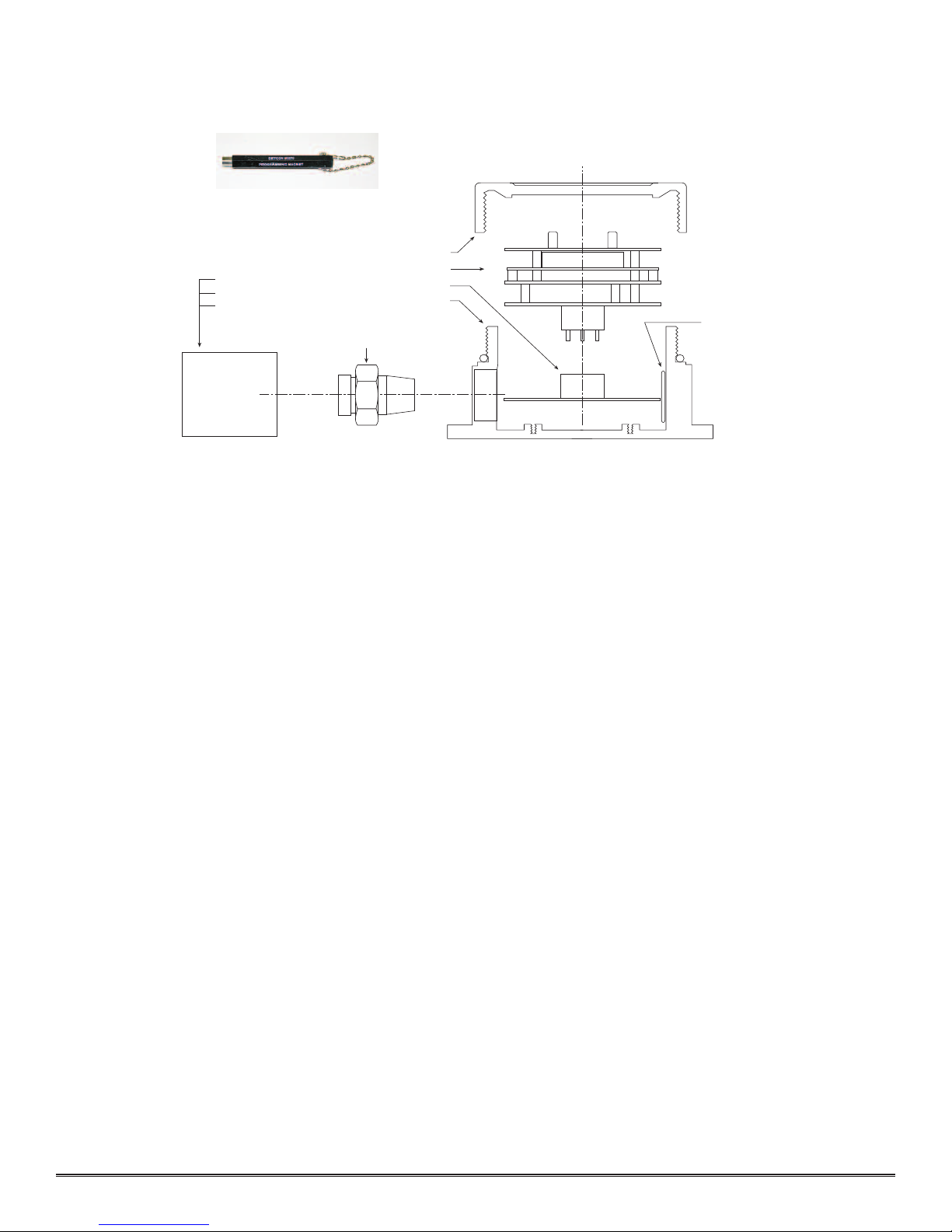
3.6.3 Programmi g Mag et Operati g I structio s
Operator nterface to M croSafe™ gas detect on products s v a magnet c sw tches located beh nd the transm tter
face plate. DO NOT remove the glass lens cover to cal brate or change programm ng parameters. Two sw tches
labeled “PGM 1” and “PGM 2” allow for complete cal brat on and programm ng w thout remov ng the enclosure
cover, thereby el m nat ng the need for area de-class f cat on or the use of hot perm ts.
A magnet c programm ng tool (see f gure 5) s used to operate the sw tches. Sw tch act on s def ned as momentary
contact, 3 second hold, and 15 second hold. In momentary contact use, the programm ng magnet s waved over a
sw tch locat on. In 3 second hold, the programm ng magnet s held n place over a sw tch locat on for 3 or more
seconds. In 15 second hold, the programm ng magnet s held n place over a sw tch locat on for 15 or more sec-
Detcon Model TP-524C Hydrogen Sulfide Sensor
PG.11
Figu e #5
detcon inc.
Program Switch #2
FLT CAL
MicroSafe™ H2S Gas Sensor
HOUSTON, TEXAS
PGM 2
PGM 1
MODEL TP-524C
CONTRAST
Fault & Cal LEDs
Program Switch #1
Menu Driven Display
Plug-in Microprocessor Control Circuit
Display Contrast Adjust
Figu e #6

onds. Three and f fteen second hold s used to enter or ex t cal brat on and program menus wh le momentary con-
tact s used to make adjustments. The locat on of “PGM 1” and “PGM 2” are shown n f gure 6.
NOTE: If, after enter ng the cal brat on or program menus, there s no nteract on w th the menu tems for more
than 30 seconds, the sensor w ll return to ts normal operat ng cond t on.
3.6.4 Setti g Ra ge
Detcon Model TP-524C can be programmed to operate n one of three ranges of detect on: 0-20 ppm, 0-50 ppm, or
0-100 ppm. To determ ne the current range sett ng follow the nstruct ons g ven n sect on 3.8.
To change the range of detect on follow the nstruct ons below:
a) F rst, enter the programm ng menu by hold ng the programm ng magnet stat onary over “PGM 2” for 15 sec-
onds unt l the d splay reads “ IEW PROG STATUS”, then w thdraw the magnet. At th s po nt you can
scroll through the programm ng menu by momentar ly wav ng the programm ng magnet over “PGM 1” or
“PGM 2”. The menu opt ons are: V ew Program Status, Set Cal Level, Set Heater Volts, Set Range, and L near ze
Sensor.
b) Next, scroll to the “SET RANGE” l st ng and then hold the programm ng magnet over “PGM 1” for 3 sec-
onds. The menu appears as “Range @ 0-### ppm” l st ng.
c) Use the programm ng magnet to make an adjustment to “PGM 1” to ncrease or “PGM 2” to decrease the read-
ng to the des red range.
d) Ex t to the programm ng menu by hold ng the programm ng magnet over “PGM1” for 3 seconds, or automat -
cally return to the programm ng menu n 30 seconds.
e) Ex t back to normal operat on by hold ng the programm ng magnet over “PGM 2” for 3 seconds, or automat -
cally return to normal operat on n 30 seconds.
NOTE: When sw tch ng between ranges, remember to readjust your Cal Level sett ng f necessary (see sect on 3.7.2).
3.6.5 Setti g Heater Voltage
The Detcon TP524C H2S sensor s factory set for the correct heater voltage and should be ready to nstall w thout
further adjustment be ng requ red. The correct heater voltage for the sensor s 5.25 VDC when set at 25°C room
temperature. It s not normally necessary to adjust th s heater voltage unless 1) the sensor s go ng to be used n
the remote mount format or 2) the sensor s be ng swapped out w th a new replacement sensor.
If the user needs to adjust the heater voltage due to the above-ment oned cond t ons, t s necessary to make the
adjustment based on the current amb ent temperature cond t on. Refer to the table below for gu dance on proper
heater voltage set-po nt:
Amb ent Temp Heater Voltage Set-po nt
25°C 5.25 VDC
35°C 5.18 VDC
45°C 5.10 VDC
55°C 5.00 VDC
15°C 5.32 VDC
5°C 5.39 VDC
-5°C 5.45 VDC
-15°C 5.50 VDC
-25°C 5.55 VDC
-40°C 5.60 VDC
3.6.6 Utility Me u
The Ut l ty Menu s used for factory author zed adjustments related to l near zat on and f lter mode. It should not
be used by the end-user n the f eld.
The “Set X Value” menu s used for adjustments of the l near zat on coeff c ent. Th s s a factory author zed adjust-
ment. The default sett ng s “6.0”.
Detcon Model TP-524C Hydrogen Sulfide Sensor
PG.12

The “Select F lter” menu s used for adjust ng the f lter mode , of wh ch, there are three modes. The correct and
default sett ng s “2”. Th s s a factory author zed adjustment.
3.7 CALIBRATION
NOTE: Before cal brat on, ver fy the range sett ng as descr bed n sect on 3.6.4.
Mate ial Requi ements
* Detcon PN 3270 M croSafe™ Programm ng Magnet
* Detcon PN 6038 Threaded Cal brat on Adapter
* Span gas conta n ng the H2S gas n a r. N trogen m xtures are not acceptable. H2S gas concentrat on s recom-
mended at 25 ppm (wh ch s the factory default for ranges 0-50 ppm and 0-100 ppm) or 10 ppm (wh ch s the
factory default for the range 0-20 ppm) at a controlled flow rate of 200 to 500 ml/m n. Other concentrat ons
can be used as long as they fall w th n allowable levels. See sect on 3.7.2 for deta ls.
* Detcon PN 985-241100-321 In-L ne Hum d fy ng Tube.
NOTE: Span gas bottles conta n 0% hum d ty and th s ultra-low hum d ty cond t on w ll cause naccurate read ngs
when used to cal brate a sensor. To prevent th s error, Detcon prescr bes the use of an In-L ne Hum d fy ng Tube,
wh ch adds the relat ve hum d ty to the span gas. The hum d fy ng tube s not necessary when us ng a gas generat-
ng cal brat on dev ce that cons sts of pumped amb ent a r and an H2S generat ng source.
3.7.2 Calibratio Procedure - Spa
CAUTION: Ver f cat on of the correct cal brat on gas level sett ng and cal brat on span gas concentrat on s
requ red before “span” cal brat on. These two numbers must be equal.
Cal brat on cons sts of enter ng the cal brat on funct on and follow ng the menu-d splayed nstruct ons. The d splay
w ll ask for the appl cat on of span gas n a spec f c concentrat on. Th s concentrat on s equal to the cal brat on gas
level sett ng. The factory default sett ng for span gas concentrat on s 10 ppm for the range 0-20 ppm and 25 ppm
for the ranges 0-50 ppm and 0-100 ppm. If a span gas conta n ng the prescr bed default concentrat on s not ava l-
able, other concentrat ons may be used as long as they fall w th n 10% and 50% of full-scale range. However, any
alternate span gas concentrat on value must be programmed v a the cal brat on gas level menu before proceed ng
w th span cal brat on. Follow the nstruct ons below for span cal brat on.
a) Ver fy the current cal brat on gas level sett ng as nd cated by the programm ng status menu. To do th s, follow
the nstruct ons n sect on 3.8 and make note of the sett ng found n l st ng number 2. The tem appears as
“CalLevel @ xxPPM”.
b) If the cal brat on gas level sett ng s equal to your cal brat on span gas concentrat on, proceed to tem “f”. If
not, adjust the cal brat on gas level sett ng so that t s equal to your cal brat on span gas concentrat on, as
nstructed n tems “c” through “e”.
c) Enter the programm ng menu by hold ng the programm ng magnet stat onary over “PGM 2” for 15 seconds
unt l the d splay reads “ IEW PROG STATUS”, then w thdraw the magnet. At th s po nt you can scroll
through the programm ng menu by momentar ly wav ng the programm ng magnet over “PGM 1” or “PGM 2”.
The menu opt ons are: V ew Program Status, Set Cal Level, Set Heater Level, Set Range, and L near ze Sensor.
d) From the programm ng menu scroll to the cal brat on level l st ng. The menu tem appears as: “SET CAL
LE EL”. Enter the menu by hold ng the programm ng magnet stat onary over “PGM 1” for 3 seconds unt l
the d splay reads “CalLevel @ ##PPM”, then w thdraw the magnet. Use the programm ng magnet to make
an adjustment to “PGM 1” to ncrease or “PGM 2” to decrease the d splay read ng unt l the read ng s equal to
the des red cal brat on span gas concentrat on. Ex t to the programm ng menu by hold ng the programm ng
magnet over “PGM1” for 3 seconds.
e) Ex t back to normal operat on by hold ng the programm ng magnet over “PGM 2” for 3 seconds, or automat -
cally return to normal operat on n 30 seconds.
f) Enter the cal brat on span menu by hold ng the programm ng magnet stat onary over “PGM 1” for 3 seconds
The d splay w ll read “1-SPAN 2-EXIT” Hold PGM 1 for 3 seconds to proceed w th a span or hold PGM 2
for 3 seconds to ex t back to normal operat on mode. After choos ng span you may, w th n 1 m nute, abort the
span procedure by a 3 second hold on PGM 2.
Detcon Model TP-524C Hydrogen Sulfide Sensor
PG.1

g) Apply the cal brat on test gas w th the hum d fy ng tube nstalled at a flow rate of 200 to 500 m ll l ters per
m nute (200ml/m n s the recommended flow). The d splay w ll read “AUTO SPAN xxPPM”. The “xx” part of
the read ng w ll change n s ngle-d g t ncrements as the sensor responds to the test gas. Dur ng the f rst 2 m n-
utes of gas appl cat on, the sensor must sat sfy a m n mum res stance change wh ch represents an “ n range” sen-
sor response (see NOTE 2 below). Then the “Auto Span” cycle s programmed for 2.5 full m nutes of exposure at
wh ch po nt an auto-adjustment s tr ggered. If, for example, automat c cal brat on s set for 25 ppm and the sen-
sor response after 2.5 m nutes s 17 ppm, the auto span funct on adjusts the read ng to 25 ppm. After th s adjust-
ment, stab l ty s ver f ed for a per od of 30 seconds. If less than 3 ppm of change occurs w th n the 30 second
t me, then auto span s completed and the d splay reads “REMO E GAS”. Remove the gas sample and observe
that the d splay clears to a read ng of 0 ppm n less than 2 to 3 m nutes.
If nstab l ty s greater than or equal to 3 ppm, auto span makes another adjustment and an add t onal 30 second
per od s allowed for f nal stab l zat on. Th s cont nues for up to a max mum of 5 m nutes total.
NOTE 1: If the sensor does not stab l ze w th n 5 m nutes dur ng AutoSpan, the sensor w ll enter nto “Stab l ty
Fault”, and alternate between “STABILITY FAULT” and sensor’s current read ng.
NOTE 2: If the sensor does not clear to <10% of range n <5 m nutes after complet ng a span cal brat on, the
sensor w ll enter nto a cal brat on fault mode wh ch w ll cause the d splay to alternate between “ZERO
FAULT” and the sensor’s current read ng.
NOTE 3: If the sensor fa ls the m n mum s gnal change cr ter a, then a “RANGE FAULT” message w ll be d s-
played alternately w th the sensor’s current read ng.
NOTE 4: When a “zero fault”, “stab l ty fault”, or “range fault” occurs, the 4-20 mA s gnal reports a 0 mA value
to nd cate there s a Fault cond t on that needs to be corrected.
3.7.3
Additional Notes
1. Upon enter ng the cal brat on menu, the 4-20 mA s gnal drops to 2 mA and s held at th s level unt l the pro-
gram returns to normal operat on.
2. If dur ng cal brat on the sensor c rcu try s unable to atta n the proper span adjustment, the sensor w ll enter nto
one of the cal brat on fault modes wh ch w ll act vate the fault LED, output a 0 mA s gnal, and cause the d splay to
alternate between the sensor’s current status read ng and the cal brat on fault screen wh ch appears as e ther:
“STABILITY FAULT, ZERO FAULT, or RANGE FAULT”. If th s occurs you must attempt to recal brate by
enter ng the cal brat on menu as descr bed n sect on 3.7.2-f. If the sensor fa ls aga n, defer to techn cal trouble
shoot ng.
3.7.4 Calibratio Freque cy
In most appl cat ons, monthly to quarterly cal brat on ntervals w ll assure rel able detect on. However, ndustr al
env ronments d ffer. Upon n t al nstallat on and comm ss on ng, close frequency tests should be performed, weekly
to monthly. Test results should be recorded and rev ewed to determ ne a su table cal brat on nterval.
3.8 STATUS OF PROGRAMMING, CALIBRATION LEVEL, HEATER LEVEL, RANGE, AND SENSOR LIFE
The programm ng menu has a “V ew Program Status” l st ng that allows the operator to v ew the present gas, range,
and software vers on number of the program, as well as the cal brat on gas level sett ng, heater level, range of detec-
t on, and est mated rema n ng sensor l fe. The programm ng menu funct ons also allow the programm ng of the cal -
brat on gas level sett ng (see sect on 3.7.2), the sensor heater level (see sect on 3.6.2), the range of detect on (see sec-
t on 3.6.4), and the ut l ty menu for factory adjustments (see sect on 3.6.6).
The follow ng procedure s used to v ew the programm ng status of the sensor:
a) F rst, enter the programm ng menu by hold ng the programm ng magnet stat onary over “PGM 2” for 15 sec-
onds unt l the d splay reads “ IEW PROG STATUS”, then w thdraw the magnet. At th s po nt you can scroll
Detcon Model TP-524C Hydrogen Sulfide Sensor
PG.14

through the programm ng menu by momentar ly wav ng the programm ng magnet over “PGM 1” or “PGM 2”.
The menu opt ons are: V ew Program Status, Set Cal Level, Set Heater Volts, Set Range, and L near ze Sensor.
b) Next, scroll to the “ IEW PROG STATUS” l st ng and then hold the programm ng magnet over “PGM 1”
for 3 seconds. The menu w ll then automat cally scroll, at f ve second ntervals, through the follow ng nforma-
t on before return ng back to the “ IEW PROG STATUS” l st ng.
1 -
The gas type, range of detect on and software vers on number. The menu tem appears as:
“H2S 0-100 2.14H”
2 - Cal brat on gas level sett ng. The menu tem appears as: “CalLevel @ xxPPM”
3 - The sensor heater voltage sett ng. The menu tem appears as: “HEATER @ #.## DC”
4 - The range of detect on sett ng. The menu tem appears as: “RANGE @ 0-###PPM”
5 - The est mated rema n ng sensor l fe. The menu tem appears as: “SENSOR LIFE 100%”
6 - The current raw res stance from the sensor. The tem appears as: “RESISTANCE XXXXX” ( n ohms)
c) Ex t back to normal operat ons by hold ng the programm ng magnet over “PGM 2” for 3 seconds, or automat -
cally return to normal operat on n 30 seconds.
3.9 PROGRAM FEATURES
Detcon M croSafe™ H2S gas sensors ncorporate a comprehens ve program to accommodate easy operator nter-
face and Fa l-Safe operat on. Program features are deta led n th s sect on. Each sensor s factory tested, pro-
grammed, and cal brated pr or to sh pment.
Ove Range
When the sensor detects gas greater than ts full scale range (20, 50, or 100 ppm), t w ll cause the d splay to flash
“20/50/100 PPM H2S” on and off. The 4-20 mA s gnal w ll report a 20 mA output.
Ze o Fault
If the sensor does not clear to <10% of range n <5 m nutes after complet ng a span cal brat on, the sensor w ll
enter nto a cal brat on fault mode wh ch w ll cause the d splay to alternate between “ZERO FAULT” and the sen-
sors current read ng. The Fault LED w ll l ght and the 4-20 mA s gnal w ll report 0 mA unt l the Fault s cleared by
perform ng a successful span cal brat on.
Stability Fault
If the sensor does not stab l ze w th n 5 m nutes dur ng AutoSpan, the sensor w ll enter nto “STABILITY FAULT”,
and alternate between “Stab l ty Fault” and sensor’s current read ng. The Fault LED w ll l ght and the 4-20 mA s g-
nal w ll report 0 mA unt l the Fault s cleared by perform ng a successful span cal brat on.
Range Fault
If the sensor fa ls the m n mum s gnal change cr ter a, then a “RANGE FAULT” message w ll be d splayed alter-
nately w th the sensor’s current read ng. The Fault LED w ll l ght and the 4-20 mA s gnal w ll report 0 mA unt l the
Fault s cleared by perform ng a successful span cal brat on.
Senso Fault
If the sensor f lm should fa l and become electr cally open, the d splay w ll nd cate: “SENSOR FAULT”.
Open Heate Fault
If the sensor heater should fa l and become electr cally open, the d splay w ll nd cate: “HEATER FAULT”.
System Fault
If the detector has an rrecoverable calculat on error, the d splay w ll nd cate: “SYSTEM FAULT”.
Memo y Fault
If new data po nts cannot successfully be stored to memory the d splay w ll nd cate: “MEMORY FAULT”.
Detcon Model TP-524C Hydrogen Sulfide Sensor
PG.15

Fail-Safe/Fault Supe vision
Model TP-524C M croSafe™ sensors are programmed for Fa l-Safe operat on. Any of the follow ng fault cond t ons
w ll llum nate the fault LED, and cause the d splay to read ts correspond ng fault cond t on: “RANGE FAULT”,
“STABILITY FAULT”, “ZERO FAULT”, “HEATER FAULT”, or “SYSTEM FAULT”. A “Heater Fault”,
“System Fault”, “Zero Fault”, and “Range Fault” w ll also cause the mA output to drop to zero (0) mA unt l the
cond t on s corrected.
Senso Life
The sensor l fe feature s a reference based on s gnal output from the sensor cell. When a sensor l fe of 25% or less
rema ns, the sensor cell should be replaced w th n a reasonable ma ntenance schedule.
3.10 DISPLAY CONTRAST ADJUST
Model TP-524C M croSafe™ sensors feature a 16 character backl t l qu d crystal d splay. L ke most LCDs, character
contrast can be affected by v ew ng angle and temperature. Temperature compensat on c rcu try ncluded n the
M croSafe™ des gn w ll compensate for th s character st c, however temperature extremes may st ll cause a sh ft n
the contrast. D splay contrast can be adjusted by the user f necessary. However, chang ng the contrast requ res that
the sensor hous ng be opened, thus declass f cat on of the area s requ red.
To adjust the d splay contrast, remove the enclosure cover and use a jewelers screwdr ver to turn the contrast adjust screw
located beneath the metall c face plate. The adjustment locat on s marked “CONTRAST”. See f gure 6 for locat on.
3.11 TROUBLE SHOOTING GUIDE
SENSOR FAULTS
Open Heater
Ver fy res stance between black and wh te w res us ng ohm-meter w th the sensor unplugged and at room tempera-
ture. Heater F lm’s normal read ng range should be 75-95 ohms. Fa lure would be an open c rcu t.
Open Sensor
Ver fy res stance between blue and yellow w res us ng ohm-meter w th the sensor unplugged and at room tempera-
ture. Sensor F lm’s normal read ng range should be 5-100 k-ohms. For sensors w th an “X” n the ser al number, the
normal read ng range should be 75 k-ohms to 2 meg-ohms. Fa lure would be open c rcu t.
SPAN CALIBRATION FAULTS – (Range, Stab l ty, Zero)
To remove the span cal brat on fault, you must repeat the cal brat on process successfully.
Range Fault
1. Check Heater Voltage Sett ng (should be 5.25 V).
2. Use hum d f er w th D st lled Water or nl ne hum d fy ng tube.
3. Check val d ty of cal gas us ng H2S pull tube or other means (must be H2S n a r background).
4. Check for obstruct ons through s/s s nter element ( nclud ng be ng wet).
5. Check sensor lot # and report to Detcon.
Zero Fault
Must recover to <10% of range before cal brat on cycle s complete and returns to normal operat on. Use bottled
a r f necessary.
Detcon Model TP-524C Hydrogen Sulfide Sensor
PG.16

Poor cal brat on Repeatab l ty
1. Check for adequate Sensor L fe.
2. Check Heater Voltage Sett ng (should be 5.25 V).
3. Use hum d f er f lled w th D st lled Water or nl ne hum d fy ng tube.
4. Check val d ty of cal gas (must be H2S n a r background).
5. Check for obstruct ons through s/s s nter element ( nclud ng be ng wet).
6. Check sensor lot # and report to Detcon.
7. Check area for presence of reduc ng gases such as Cl2 and ozone wh ch may cause low read ngs.
Unstable output/ Sudden sp k ng
Unstable power supply, Inadequate ground ng, Inadequate RFI protect on.
1. Ver fy Power source.
2. Contact Detcon to opt m ze sh eld ng and ground ng.
3. Add RFI protect on accessory.
Nu sance Alarms
1. Check condulet for accumulated water and abnormal corros on.
If Nu sance alarms happen ng at n ght suspect condensat on n condulet.
2. Add/Replace Detcon Condensat on Prevent on Packet P/N 960-202200-000
Memory or Error reports
1. Re n t al ze Sensor - Unplug transm tter, replug transm tter then sw pe magnet over PGM 1 n the f rst 3 seconds.
Th s w ll clear the processor and recover from error state. Remember to put n all customer sett ngs for range, and
cal gas level after re- n t al zat on.
Non readable d splay
1. If blue background, nstall sunshade to reduce temperature.
2. If poor contrast, adjust contrast pot accord ngly.
Noth ng D splayed – Transm tter not Respond ng
1. Ver fy condulet has no accumulated water or abnormal corros on.
2. Ver fy requ red DC power s appl ed to correct term nals.
3. Swap w th a known-good transm tter to determ ne f transm tter s faulty.
Bad 4-20 mA output or RS485 Output
1. Check that w r ng s connected to correct term nal outputs.
Swap w th a known-good transm tter to determ ne f transm tter s faulty.
3.12 SPARE PARTS LIST
600-610000-000 Sensor splash guard
943-000006-038 Threaded Cal brat on Adapter
399-800000-000 H2S sensor n sta nless steel hous ng
925-015400-100 TP-524C Plug- n control c rcu t
500-005065-007 Connector board
327-000000-000 Programm ng Magnet
897-850901-010 3 port enclosure w th glass l d
960-202200-000 Condensat on prevent on packet (replace annually).
985-241100-321 In-L ne Hum d fy ng Tube
943-020000-000 Span Gas K t: Includes cal brat on adapter, In-L ne Hum d fy ng Tube, 200 ml/m span
gas regulator, and carry ng case. Does not nclude span gas.
942-010112-010 Span gas bottle conta n ng 58 l ters 10ppm H2S n a r (operat ng range dependent).
942-010112-025 Span gas bottle conta n ng 58 l ters 25ppm H2S n a r (operat ng range dependent).
942-010112-050 Span gas bottle conta n ng 58 l ters 50ppm H2S n a r (operat ng range dependent).
943-090005-502 200 ml/m regulator for span gas bottle
Detcon Model TP-524C Hydrogen Sulfide Sensor
PG.17
3.13 WARRANTY
Detcon, Inc., as manufacturer, warrants each hydrogen sulf de sensor element (PN 399-800000-000), for a ten year
per od under the cond t ons descr bed as follows: The warranty per od beg ns on the date of sh pment to the or g -
nal purchaser, and follows the schedule below. The sensor element s warranted to be free from defects n mater al
and workmansh p. Should any sensor fa l to perform n accordance w th publ shed spec f cat ons w th n the warran-
ty per od, return the defect ve part to Detcon, Inc., 4055 Technology Forest Blvd, Su te 100, The Woodlands, Texas
77381, for necessary repa rs or replacement.
F rst year No Charge
2nd-5th years $25.00 handl ng charge
6th year $60.00 handl ng charge
7th year $96.00 handl ng charge
8th year $120.00 handl ng charge
9th year $150.00 handl ng charge
10th year $176.00 handl ng charge
Warranty vo ded $200.00 charge
Non-warranty $295.00 charge
Te ms & Conditions
* The or g nal ser al number must be leg ble on each sensor element base.
* Sh pp ng po nt s FOB the Detcon factory.
* Net payment s due w th n 30 days of nvo ce.
* Detcon, Inc. reserves the r ght to refund the or g nal purchase pr ce n l eu of sensor replacement.
3.14 SERVICE POLICY
Detcon, Inc., as manufacturer, warrants under ntended normal use each new M croSafe™ plug- n control c rcu t to
be free from defects n mater al and workmansh p for a per od of two years from the date of sh pment to the or g -
nal purchaser. Detcon, Inc., further prov des for a f ve year f xed fee serv ce pol cy where n any fa led transm tter
shall be repa red or replaced as s deemed necessary by Detcon, Inc., for a f xed fee of $65.00. The f xed fee serv ce
pol cy shall affect any factory repa r for the per od follow ng the two year warranty and shall end f ve years after
exp rat on of the warranty. All warrant es and serv ce pol c es are FOB the Detcon fac l ty located n The
Woodlands, Texas.
Detcon Model TP-524C Hydrogen Sulfide Sensor
PG.18
Spash Guard
Rain Shield
Enclosure less cover
Connector Board
Calibration Adapter
Enclosure glass lens cover
Plug-in control circuit
H2S Sensor in Housing
Programming Magnet
Condensation
Prevention Packet
(replace annually)
Figu e #8
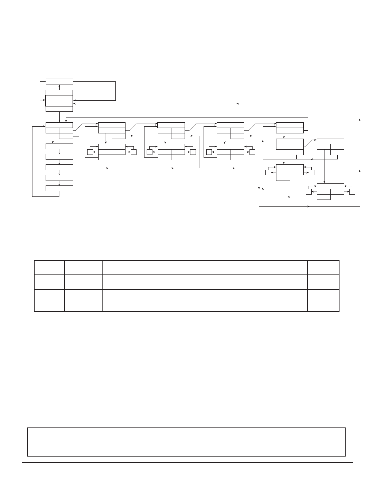
3.15 SOFTWARE FLOW CHART
3.16 REVISION LOG
Detcon Model TP-524C Hydrogen Sulfide Sensor
PG.19
NORMAL
OPERATION
PGM1 (M) PGM2 (M)
PGM1 (3)
INC
DEC
PGM1 (3) PGM2 (M)
LEGEND
PGM1 - program switch location #1
PGM2 - program switch location #2
(M) - momentary pass of magnet
(3) - 3 second hold of magnet
(30) - 30 second hold of magnet
INC - increase
DEC - decrease
# - numeric value
AUTO SPAN
GAS RANGE V#.#
PGM1 (3) PGM2 (M)
VIEW PROG STATUS
CalLevel @ ##PPM
PGM1 (10) PGM2 (3)
SET CAL LEVEL
PGM2 (3) PGM2 (3)
SENSOR LIFE ##%
PGM1 (3)
PGM2 (30)
SET X VALUE
UTILITY MENU
CAL LEVEL @ ##PPM
HEATER @ #.##VDC
PGM1 (M) PGM2 (M)
PGM1 (3)
INC
DEC
PGM1 (3) PGM2 (M)
PGM2 (3)
HEATER @ ##VDC
SET HEATER VOLTS
PGM1 (M) PGM2 (M)
PGM1 (3)
INC
DEC
PGM1 (3) PGM2 (M)
PGM2 (3)
RANGE @ 0-###PPM
SET RANGE
RANGE @ 0-###PPM
PGM1 (3) PGM2 (M)
PGM2 (3)
SET FILTER
PGM1 (3) PGM2 (M)
PGM2 (3)
PGM1 (M) PGM2 (M)
PGM1 (3)
INC
DEC
X= #.#
PGM1 (M) PGM2 (M)
PGM1 (3)
INC
DEC
FILTER = #
www.detcon.com • [email protected]
Rev s on Date Changes Made Approval
2.4 02/01/2010 Prev ous rev s on BM
2.5 05/09/2012 Change to Interference table (Methyl Mercaptan), updated spare parts, rev sed
sh pp ng addresss, added rev s on log
BM
Table of contents
Other Detcon Accessories manuals

Detcon
Detcon TP-700 User manual

Detcon
Detcon CXT-IR User manual

Detcon
Detcon SmartWireless CX User manual

Detcon
Detcon DM-100 Series User manual

Detcon
Detcon DM-500IS OLED Series User manual

Detcon
Detcon TP-524D User manual

Detcon
Detcon FP-524D User manual

Detcon
Detcon DM-700 User manual

Detcon
Detcon CXT-DM User manual

Detcon
Detcon FP-700 User manual


-G6 Instructions for use")


