Detcon CXT-IR User manual


Model CXT-IR
Model CXT-IR ii
This page left intentionally blank

Model CXT-IR
Model CXT-IR iii
Table of Contents
Introduction ................................................................................................................................................. 1
1.1 Description.......................................................................................................................................... 1
1.2 Modular Design .................................................................................................................................. 3
1.2.1 CXT-IR Intelligent Transmitter Module ........................................................................................ 3
1.2.2 Field Replaceable Sensor................................................................................................................ 4
1.3 CXT Wireless Network....................................................................................................................... 5
1.4 Battery Pack Options .......................................................................................................................... 5
1.4.1 Detconꞌs Smart Battery Pack .......................................................................................................... 5
1.4.2 D Cell Lithium Battery Pack .......................................................................................................... 7
1.4.3 Tri-C Lithium Battery Pack............................................................................................................ 8
Installation................................................................................................................................................... 9
2.1 Hazardous Locations Installation Guidelines for Safe Use................................................................. 9
2.2 Sensor Placement.............................................................................................................................. 10
2.3 Sensor Contaminants and Interference ............................................................................................. 12
2.4 Sensor Mounting............................................................................................................................... 12
2.5 Electrical Installation........................................................................................................................ 15
2.5.1 Applying Power to the Unit.......................................................................................................... 15
2.6 Initial Start Up................................................................................................................................... 17
2.6.1 Combustible Gas Sensors............................................................................................................. 17
Operation ................................................................................................................................................... 18
3.1 Operator Interface............................................................................................................................. 19
3.2 Normal Operation ............................................................................................................................. 20
3.3 Calibration Mode.............................................................................................................................. 20
3.3.1 AutoZero....................................................................................................................................... 21
3.3.2 AutoSpan...................................................................................................................................... 21
3.4 Program Mode .................................................................................................................................. 23
3.4.1 Navigating Program Mode ........................................................................................................... 23
3.4.2 View Sensor Status....................................................................................................................... 24
3.4.3 Set Gas Type................................................................................................................................. 26
3.4.4 Set AutoSpan Level...................................................................................................................... 26
3.4.5 Set Gas Factor............................................................................................................................... 26
3.4.6 Bump Test .................................................................................................................................... 28
3.4.7 Restore Defaults ........................................................................................................................... 28
3.4.8 Set RF Channel............................................................................................................................. 28
3.4.9 Alarm Settings.............................................................................................................................. 29
3.4.10 Set Modbus ID ......................................................................................................................... 29
3.5 Fault Diagnostic/Failsafe Feature ..................................................................................................... 29
Modbus™ TM Communications............................................................................................................... 30
4.1 General Modbus™ Description ........................................................................................................ 30
4.1.1 Modbus™ Exceptions .................................................................................................................. 30
4.1.2Modbus™ Broadcast Requests..................................................................................................... 31
4.2 Modbus™ Register Map and Description......................................................................................... 31
4.2.1 CXT Sensor Registers .................................................................................................................. 33
4.2.2 CXT Transceiver Registers .......................................................................................................... 34
Service and Maintenance........................................................................................................................... 36
5.1 Replacement of the Batteries/Battery Pack....................................................................................... 36
5.1.1 Units with 12V Smart Battery Pack.............................................................................................. 36
5.1.2 Units with D-Size Non-Rechargeable Batteries ........................................................................... 36
5.1.3 Units with Tri-‘C’ sized Lithium Battery Holder......................................................................... 38
5.2 Replacement of Plug-in Sensor......................................................................................................... 39
5.3 Replacement of ITM – Aluminum Junction Box.............................................................................. 40

Model CXT-IR
Model CXT-IR iv
5.4 Replacement of ITM – Stainless Steel Mini Condulet...................................................................... 40
Troubleshooting Guide.............................................................................................................................. 41
Customer Support and Service Policy....................................................................................................... 43
CXT-IR Sensor Warranty.......................................................................................................................... 44
Appendix ................................................................................................................................................... 45
9.1 Specifications.................................................................................................................................... 45
9.1.1 System Specifications................................................................................................................... 45
9.1.2 Environmental Specifications....................................................................................................... 45
9.1.3 Electrical Specifications ............................................................................................................... 45
9.1.4 Mechanical Specifications (ITM Only)........................................................................................ 46
9.2 Spare Parts, Sensor Accessories, Calibration Equipment................................................................. 46
9.3 Revision Log..................................................................................................................................... 47
Table of Figures
Figure 1 Sensor Cell Construction ....................................................................................................................... 2
Figure 2 Principle of Operation............................................................................................................................ 2
Figure 3 Sensor Assembly Breakaway................................................................................................................. 3
Figure 4 ITM Circuit Functional Block Diagram................................................................................................. 4
Figure 5 Sensor Assembly Front View ................................................................................................................ 4
Figure 6 Plug-in Sensor........................................................................................................................................ 4
Figure 7 Smart Battery Pack ................................................................................................................................ 6
Figure 8 Quad Battery Charger ............................................................................................................................ 6
Figure 9 D-Cell Lithium Battery Pack ................................................................................................................. 7
Figure 10 Tri C Lithium Battery Holder .............................................................................................................. 8
Figure 11 Approval Labels................................................................................................................................... 9
Figure 12 CXT-IR Sensor with D or Smart Battery Pack Mounting Dimensions ............................................. 13
Figure 13 CXT-IR Sensor with C-Cell Batteries ............................................................................................... 14
Figure 14 Terminal Interconnect for Smart Battery Pack .................................................................................. 16
Figure 15 Magnetic Programming Tool............................................................................................................. 18
Figure 16 Magnetic Programming Switches...................................................................................................... 18
Figure 17 Menu Flow Chart............................................................................................................................... 20
Figure 18 Modbus™ Frame Format................................................................................................................... 30
Figure 19 Battery Orientation Diagram.............................................................................................................. 37
Figure 20 Battery Orientation Diagram.............................................................................................................. 38
Figure 21 Sensor Cell and ITM Mating ............................................................................................................. 39
List of Tables
Table 1 Gas Factors............................................................................................................................................ 27
Table 2 Exception Codes.................................................................................................................................... 31
Table 3 CXT-IR Register Map........................................................................................................................... 32
Table 4 Spare Parts, Sensor Accessories, and Calibration Equipment............................................................... 46
Table 5 Revision Log......................................................................................................................................... 47
Shipping Address: 4055 Technology Forest, Suite 100, The Woodlands, Texas 77381
Mailing Address: P.O. Box 8067, The Woodlands Texas 77387-8067
Phone: 888.367.4286, 281.367.4100 • Fax: 281.292.2860 •www.detcon.com •
Model CXT-IR
CXT-IR Instruction Manual Rev. 2.1 Page 1 of 48
Introduction
1.1 Description
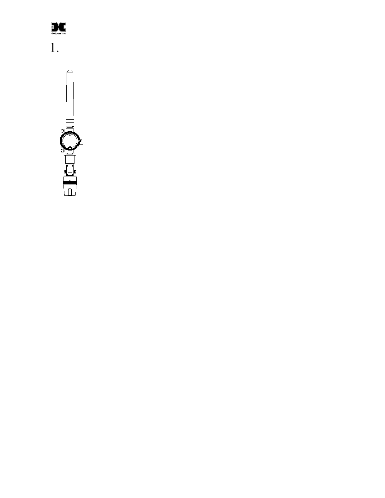
Detcon Model CXT-IR combustible gas sensors are non-intrusive “Smart” sensors designed to
detect and monitor combustible hydrocarbon gases in the air with a detection range of 0-100%
LEL (Lower Explosive Limit). The sensor features an LED display of current reading, fault and
calibration status. A primary feature of the sensor is its method of automatic calibration, which
guides the user through each step via fully scripted instructions illustrated on the LED display.
The microprocessor-supervised electronics are enclosed in an encapsulated module and housed
in an explosion proof casting.
The unit includes:
•a built in 2.4GHz radio to transmit status wirelessly to a controller,
•a four character alpha/numeric LED to display sensor readings, and
•a menu-driven interface when the hand-held programming magnet is in use.
•an optional strobe
Non-Dispersive Infrared (NDIR) Optical Sensor Technology
The sensor technology is designed as a miniature plug-in replaceable component, which can easily be changed
out in the field.
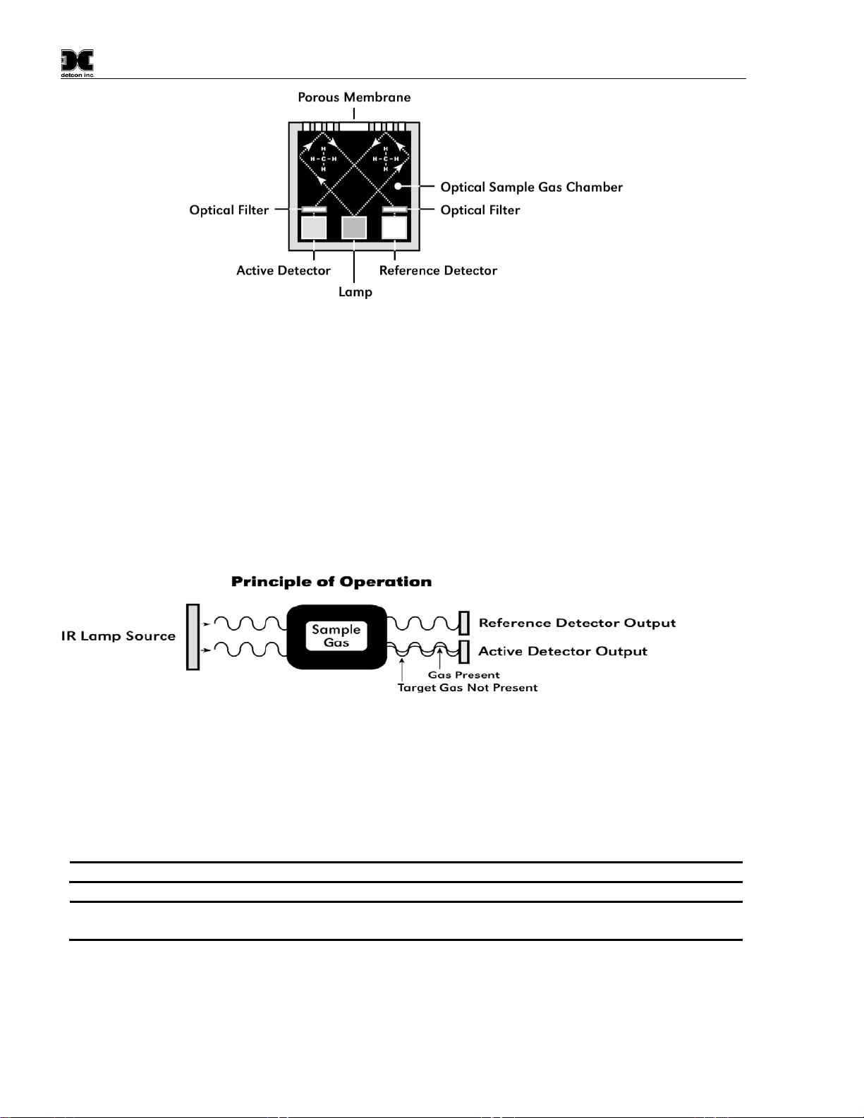
The NDIR sensor consists of (Figure 1):
•one infrared lamp source,
•two pyroelectric detectors (active and reference),
•and one optical gas sample chamber.
The lamp source produces infrared radiation, which interacts with the target gas as it is reflected through the
optical gas sample chamber. The infrared radiation contacts each of the two pyroelectric detectors at the
completion of the optical path. The active pyroelectric detector is covered by a filter specific to the part of the
IR spectrum where the target gas absorbs light. The reference pyroelectric detector is covered by a filter specific
to the non-absorbing part of the IR spectrum. When the target gas is present, it absorbs IR radiation and the
signal output from the active detective decreases accordingly. The reference detector output remains unchanged.
The ratio of the active and reference detector outputs are then used to compute the target gas concentration.
The technique is referred to as non-selective and may be used to monitor most any combustible hydrocarbon
gas. Unlike catalytic bead type sensors, Detcon IR sensors are completely resistant to poisoning from corrosive
gases and can operate in the absence of an oxygen background. The sensors are characteristically stable and
capable of providing reliable performance for periods exceeding 5 years in most industrial environments.
Model CXT-IR
CXT-IR Instruction Manual Rev. 2.1 Page 2 of 48
Figure 1 Sensor Cell Construction
Principle of Operation
The target gas diffuses through a sintered stainless steel flame arrestor and into the volume of the sample gas
optical chamber. An alternating miniature lamp provides a cyclical IR radiation source, which reflects through
the optical gas sample chamber and terminates at the two pyroelectric detectors. The active and reference
pyroelectric detectors each give an output which measures the intensity of the radiation contacting their surface.
The active detector is covered by an optical filter specific to the part of the IR spectrum where the target gas
absorbs light. The reference detector is covered by a filter specific to the non-absorbing part of the IR spectrum.
When present, the target gas absorbs a fraction of the IR radiation and the signal output from the active detector
decreases accordingly. The signal output of the reference detector remains unchanged in the presence of the
target gas. The ratio of the active/reference signal outputs is then used to compute the target gas concentration.
By using the ratio of the active/reference signal outputs, measurement drift caused by the changes in the intensity
of the IR lamp source or changes in the optical path’s reflectivity is prevented (Figure 2).
Figure 2 Principle of Operation
Performance Characteristics
The IR sensor maintains strong sensitivity to most all combustible hydrocarbon gases within the LEL range.
When compared with the typical catalytic bead LEL sensor, the IR sensor exhibits improved long-term zero and
span stability. Typical zero calibration intervals are quarterly to semi-annual and typical span intervals are semi-
annual to annual.
NOTE
Actual field experience is always the best determination of appropriate calibration intervals.
NOTE
The CXT-IR sensor will not respond to combustible gases that are not hydrocarbons, such as
H2, NH3, CO, H2S….etc. It can only be used to measure hydrocarbon type gases.
The IR sensor generates different signal sensitivity levels for different combustible hydrocarbon target gases.
Unless otherwise specified the CXT-IR sensor will be factory calibrated for methane service. If the target
hydrocarbon gas is other than methane, then theunit will have to be span calibrated and configured in accordance
with this CXT-IR sensor instruction manual.
Model CXT-IR
CXT-IR Instruction Manual Rev. 2.1 Page 3 of 48
1.2 Modular Design
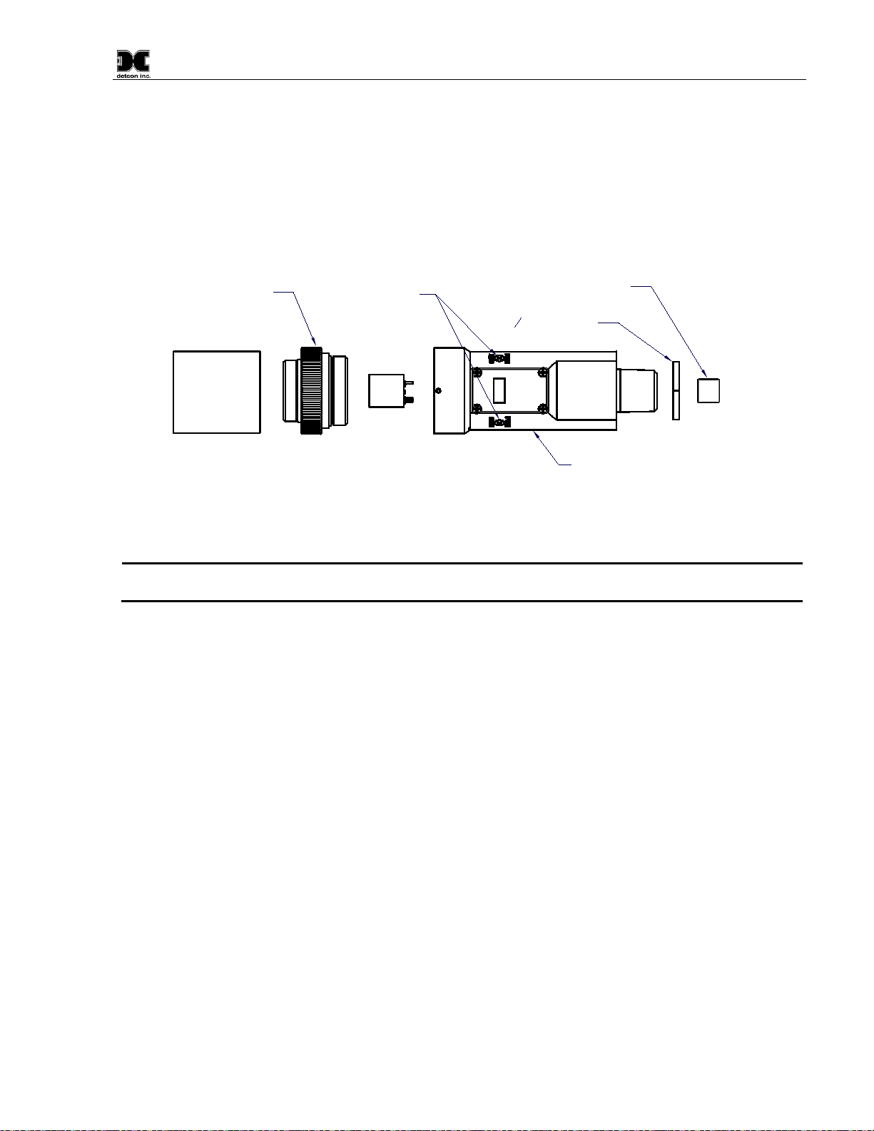
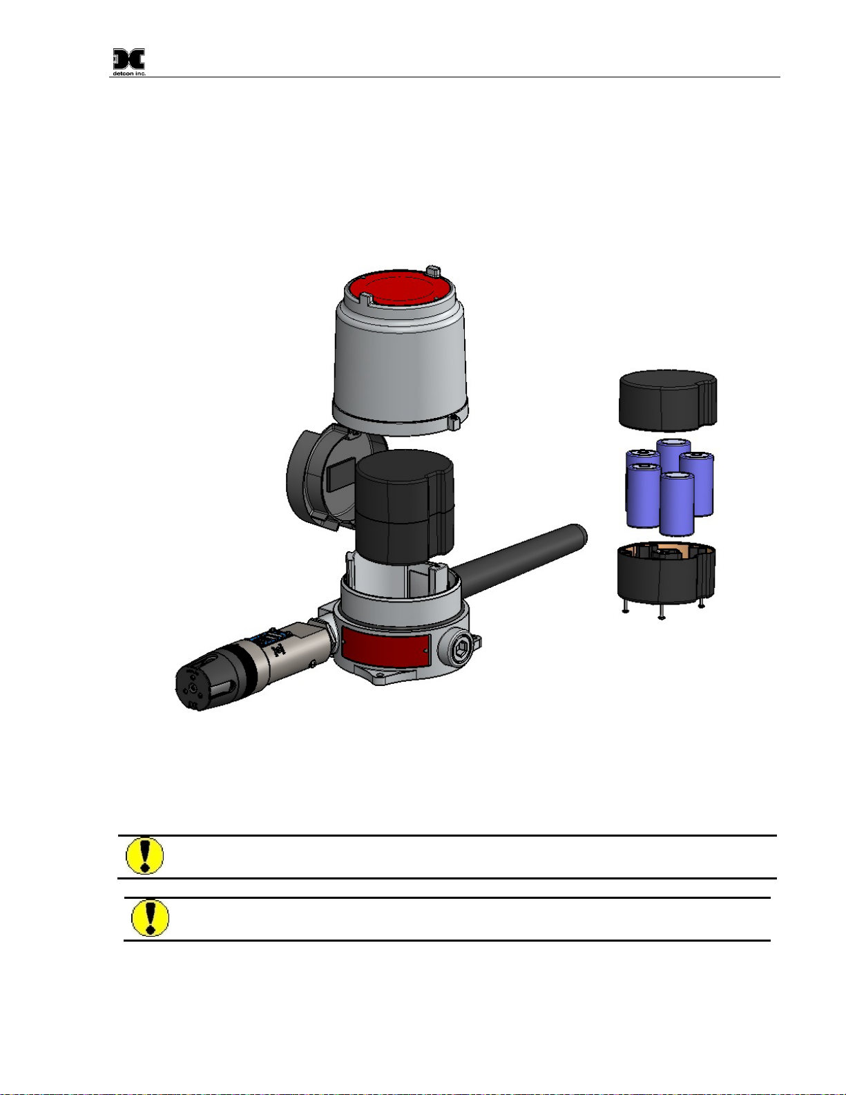
The Model CXT-IR Sensor Assembly is completely modular and is made up of four parts (Figure 3)
1) CXT-IR Intelligent Transmitter Module (ITM)
2) Plug-in infrared Sensor
3) CXT Series Bottom Housing
4) Splash Guard
100 Series Bottom
Housing Assembly
Plug-in
Replaceable
Sensor Cell Intelligent Transmitter Module (ITM)
Micro-processor controlled circuit
encapsulated in an Explosion proof
housing.
Magnetic
Programming
Switches
Rain Shield
34" NPT Locking
Nut
Ferrite Bead
Figure 3 Sensor Assembly Breakaway
NOTE
All metal components are constructed from electro polished 316 Stainless Steel in order to
maximize corrosion resistance in harsh environments.
1.2.1 CXT-IR Intelligent Transmitter Module
The Intelligent Transmitter Module (ITM) is a fully encapsulated microprocessor-based package that accepts a
plug-in field replaceable combustible gas sensor.
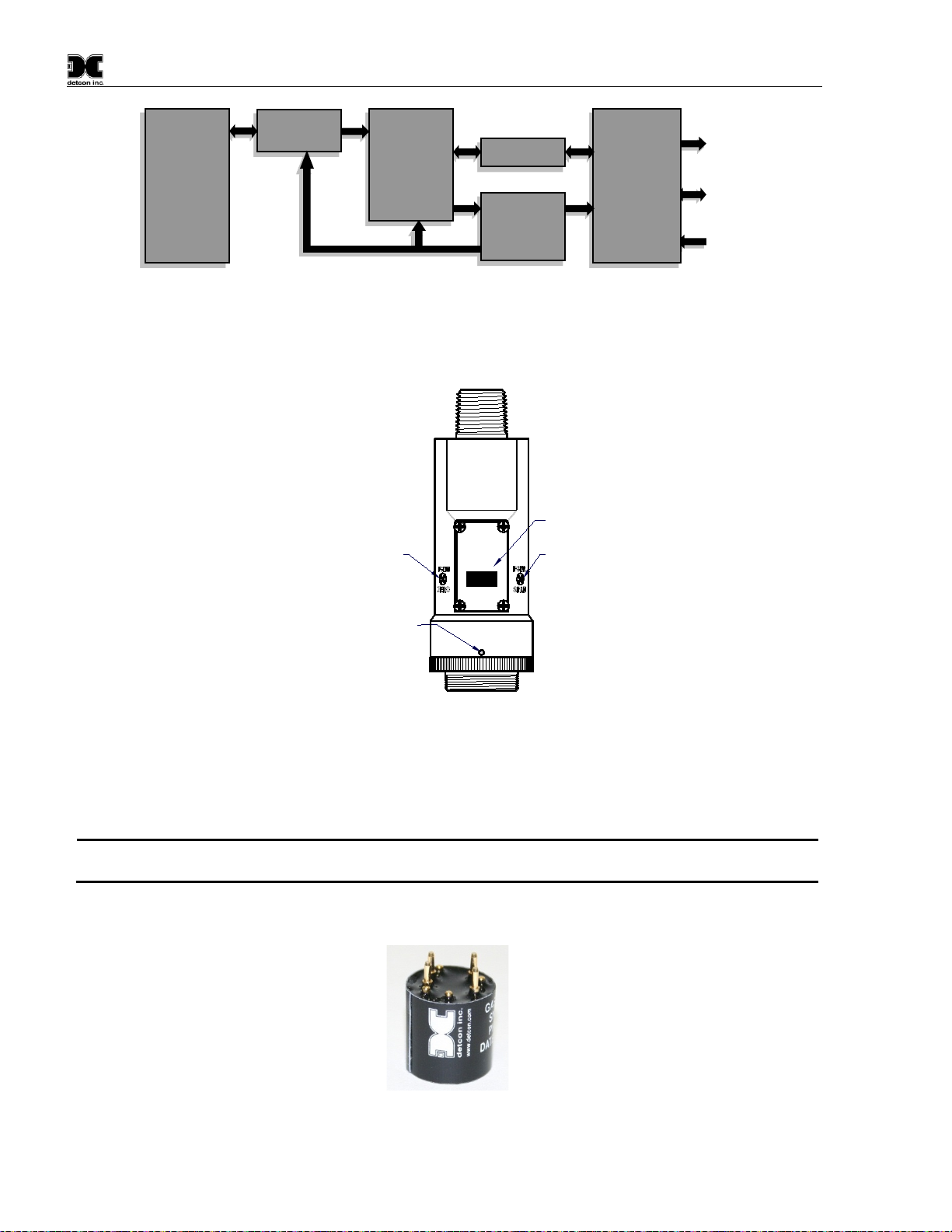
Circuit functions include (Figure 4):
•extensive I/O circuit protection,
•sensor pre-amplifier,
•on-board power supplies,
•microprocessor,
•LED display,
•magnetic programming switches,
•built-in 2.4GHz radio
Magnetic program switches located on either side of the LED Display are activated by a hand-held magnetic
programming tool, allowing a non-intrusive operator interface with the ITM. The program switches allows
calibration without declassifying the area.
Model CXT-IR
CXT-IR Instruction Manual Rev. 2.1 Page 4 of 48
Figure 4 ITM Circuit Functional Block Diagram
Program Switch #1
LED Display
Program Switch #2
Housing Bottom
Locking Set-Screw
detcon inc.
LEL Sensor
detcon inc.
MODEL
CXT- IR
Figure 5 Sensor Assembly Front View
1.2.2 Field Replaceable Sensor
Detconꞌs infrared gas sensors are field proven, plug-in sensors with over-sized gold-plated connections that
eliminate corrosion problems. The sensor can be accessed and replaced in the field easily by releasing the locking
screw and unthreading the splashguard adapter assembly.
NOTE
Detconꞌs combustible sensors have a long shelf life and are supported by an industry-leading
warranty.
Figure 6 Plug-in Sensor
I/O
Circuit
Protection
Accessory
connections
Antenna
Power In
Wireless
Power
supplies
Micro-
Processor
Intrinsically
Safe Barrier
Plug-In
Sensor

Model CXT-IR
CXT-IR Instruction Manual Rev. 2.1 Page 5 of 48
1.3 CXT Wireless Network
The CXT-IR sensor utilizes a transceiver radio, based on the IEEE 802.15.4 standard. The transceiver operates
at 2.4 GHz using DSSS encoding for robustness. DSSS was initially used by the military to resist jamming but
later was widely adopted for wireless implementations since it was robust in noisy environments. DSSS
transmits data across a wider frequency range than the actual frequency range required for the information. This
operation minimizes cross talk and interference from other transceivers and is less susceptible to noise from
other sources.
The IEEE 802.15.4 defines 16 separate RF Channels that can be used in the 2.4 GHz range. The default channel
is 1 but can be changed if there is RF interference or if there is an existing network using that channel.
Transceivers will only respond to other transceivers with the same RF Channel.
NOTE
If there are multiple CXT-IR networks in the same vicinity, each system must reside on a
different RF Channel to keep data from one appearing on the other system.
The 802.15.4 standard also implements a mesh network allowing any CXT-IR transceiver to relay or repeat data
between adjacent neighbors. This makes the network very robust and provides the following immediate benefits.
•Allows re-routing of data in case of loss of a transceiver
•Allows re-routing around wireless obstacles
•Longer distances between transceivers because data can “hop” from one transceiver to the next
•Included in sensor, controller and alarm station transceivers
•CXT-IR transceivers can be deployed with less concern about physical location.
1.4 Battery Pack Options
The CXT-IR can be powered by a battery pack that enables the IR to be remotely mounted without the need for
external cabling. Detcon offers several battery pack options that are factory installed. Contact Detcon for more
information on these options.
1.4.1 Detconꞌs Smart Battery Pack
The Detcon’s plug-in Smart Battery Packs provides an output of 12VDC (See Figure 7). There are two versions
of the Smart Battery Pack. The first one is the 12V 2200mAh battery Pack (Detcon’s part number 976-0BP303-
120) and the second is the 12V 2900mAh Battery Pack. The CXT-DM monitors the battery pack for remaining
battery life. The battery packs consists of rechargeable Lithium-Ion batteries and are equipped with integrated
safety electronics that include a fuel gauge, voltage monitor, and current and temperature monitoring circuits.
This “smart” circuitry continuously monitors the battery’s condition and reports critical status information to the
wireless transceiver via the Modbus™ registers. The battery packs are designed to plug into an 8-pin Beau
connector on the Terminal Board that the sensor is connected to. The battery Pack and Terminal Board are
housed in Detcon’s Aluminum Condulet to protect them from exposure to outside elements and still provide
Class I Div 1, C, and D approvals. Operating periods before recharge will vary based on sensor attached, but
can be as long as 3.5 months for the 12V 2200mAh battery pack, and 5 months for the 12V 2900mAh battery
pack before battery recharging is required. Improper use of the battery pack may be hazardous to personnel or
the environment and will void the warranty.
Model CXT-IR
CXT-IR Instruction Manual Rev. 2.1 Page 6 of 48
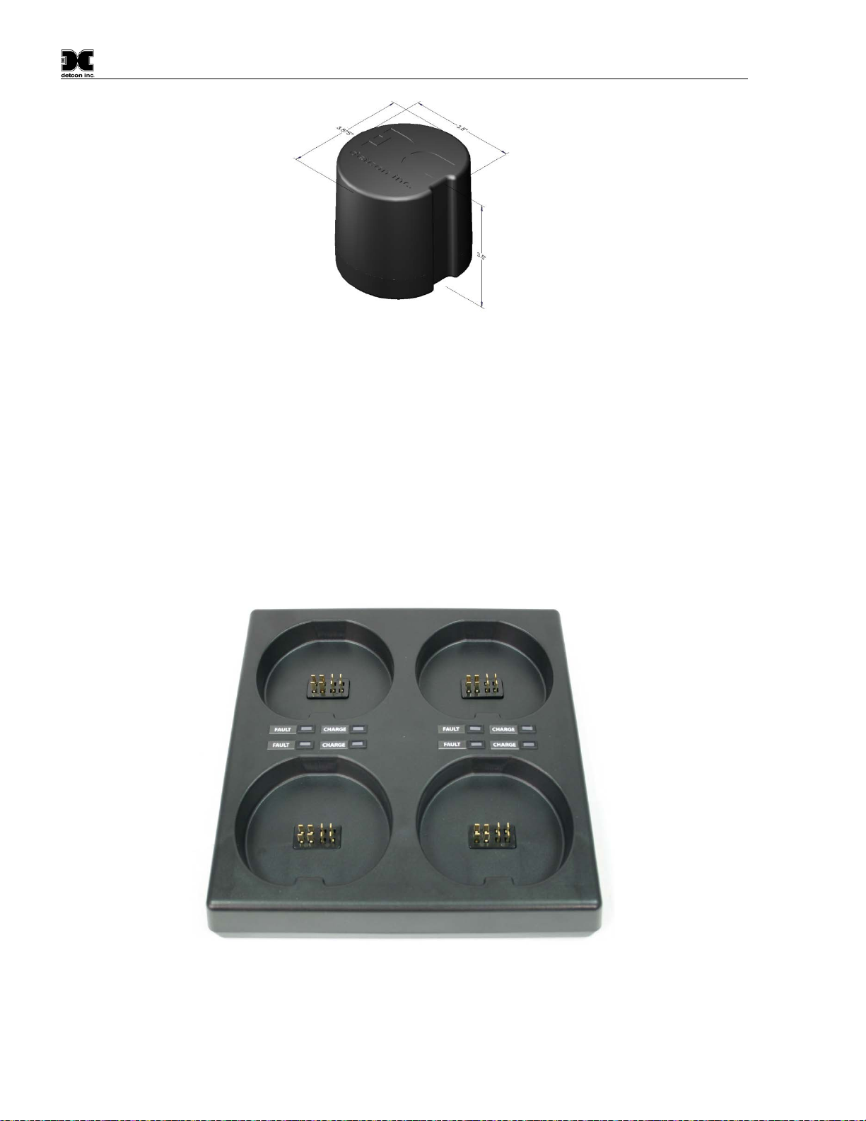
Figure 7 Smart Battery Pack
Quad Battery Charger (Optional)
Detcon’s Smart Battery Pack can be charged as needed using Detcon’s optional Quad Battery Charger which
can charge up to four battery packs at one time. The Quad Battery Charger comes with a plug-in AC/DC adapter
that plugs into a standard 100-240VAC outlet for power. The DC end of the adapter plugs into the DC power
jack of the charger providing 24VDC. The Quad Battery Charger has four charging ports, each with 8-pin Beau
connectors for battery pack connection. The ports and connectors are keyed to prevent incorrect positioning and
connection. Each port has its own “FAULT” LED indicator and “CHARGE” LED indicator and will display
either a red light or green light depending on the status of each battery being charged. Charging times will vary
depending on the charge state of each battery pack, but a full charge of a depleted battery pack can take up to 24
hours.
Figure 8 Quad Battery Charger
Model CXT-IR
CXT-IR Instruction Manual Rev. 2.1 Page 7 of 48
1.4.2 D Cell Lithium Battery Pack
The D Cell Lithium Battery Pack (Figure 9) contains five 3.6V Lithium Primary D size batteries which are not
re-chargeable. This battery pack provides the unit with 18 volts. The batteries are contained in a battery holder
mounted in Detconꞌs aluminum explosion proof condulet. The CXT-DM sensors will operate up to 9 months
before battery replacement is needed. The battery Pack and Terminal Board are housed in Detcon’s Aluminum
Condulet to protect them from exposure to outside elements and still provide Class I Div 1, C, and D approvals.
Figure 9 D-Cell Lithium Battery Pack
CAUTION
Warning – Explosion Hazard – Batteries must only be changed in an area free of
ignitable concentrations.
CAUTION
Warning – Explosion Hazard – Batteries must only be recharged in an area free of
ignitable concentrations.
Model CXT-IR
CXT-IR Instruction Manual Rev. 2.1 Page 8 of 48
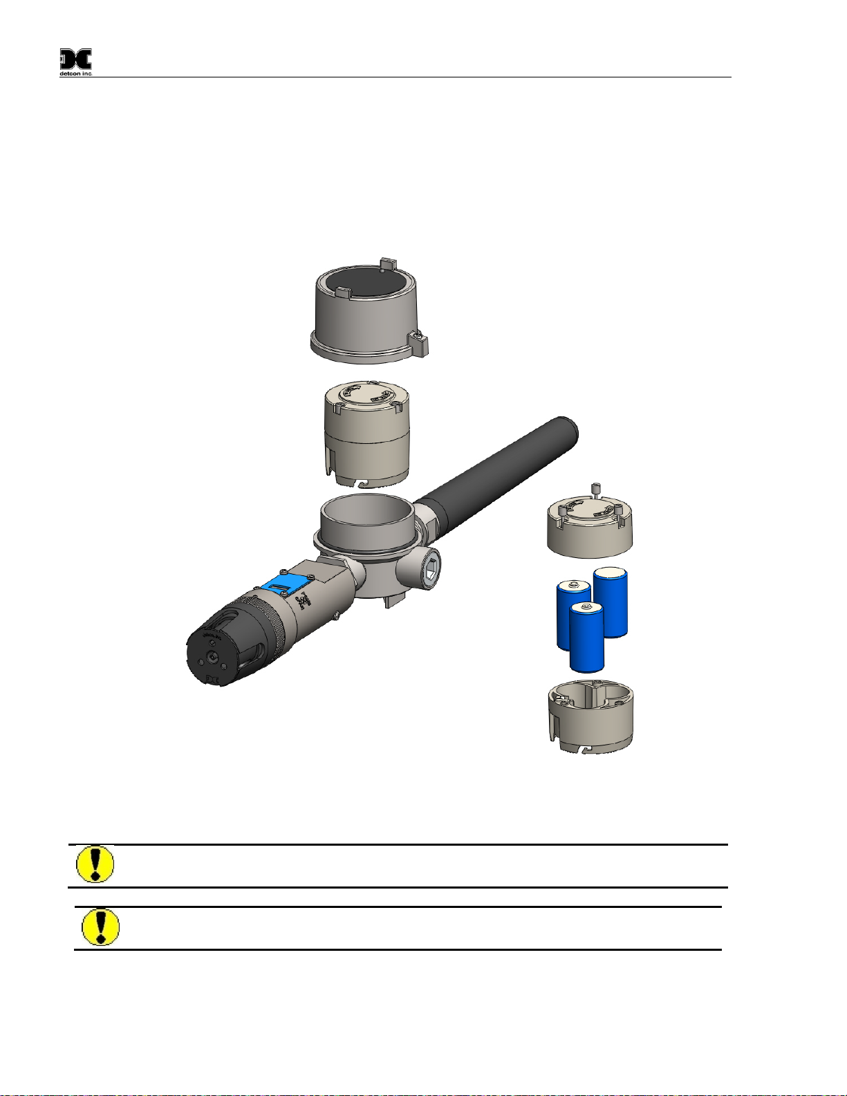
1.4.3 Tri-C Lithium Battery Pack
The Tri-C Lithium Battery Pack (Figure 10) contains three 3.6V Lithium Primary C size batteries which are not
re-chargeable. This battery pack offers a more compact size, and provides the unit with 10.8 volts. The batteries
are contained in a battery holder mounted in Detconꞌs stainless steel explosion proof mini-condulet. This option
offers a smaller foot print, but provides less run time than Detcon’s Smart Battery Pack. The CXT-IR sensors
can operate for up to 60 days before battery replacement is needed. The addition of Detconꞌs Stainless Steel Mini
Condulet provides Class I Div 1, Group C, and D ratings.
Figure 10 Tri C Lithium Battery Holder
CAUTION
Warning – Explosion Hazard – Batteries must only be changed in an area free of
ignitable concentrations.
CAUTION
Warning – Explosion Hazard – Batteries must only be recharged in an area free of
ignitable concentrations.
Model CXT-IR
CXT-IR Instruction Manual Rev. 2.1 Page 9 of 48
Installation
2.1 Hazardous Locations Installation Guidelines for Safe Use
NOTE: The CXT-IR assembly with strobe is not rated for Class I Division 1 or Class I Zone 1
applications. The following guidelines only apply to a CXT-DM assembly without a strobe.
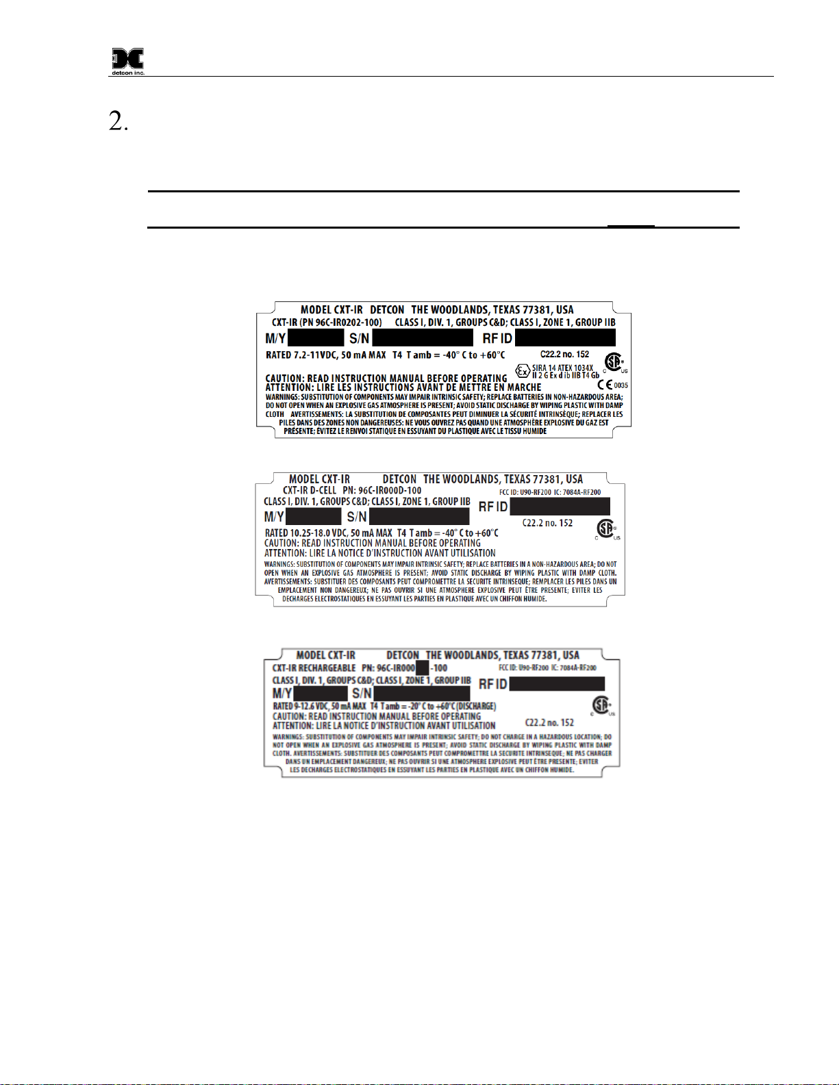
1. Install the sensor only in areas with classifications matching the approval label. Follow all warnings
listed on the label.
Figure 11 Approval Labels
2. Do not remove the junction box cover while in the classified are unless it is conformed the there is no
explosive gas levels in the area.
3. A good ground connection should be verified between the sensor’s metal enclosure and the junction
box. If a good ground connection is not made, the sensor can be grounded to the junction box using the
sensor’s external ground lug. Verify a good ground connection between the junction box and earth
ground.
4. Proper precautions should be taken during installing and maintenance to avoid the build-up of static
charge on the plastic components of the sensor (Splash Guard and Antenna Dome Cover) Wipe with
damp cloth on plastic components to avoid static discharge.

Model CXT-IR
CXT-IR Instruction Manual Rev. 2.1 Page 10 of 48
5. Do not substitute components. Substitution of components may impair the intrinsic safety rating.
6. Do not operate the sensor outside of the stated operating temperature limits.
7. Do not operate the sensor outside the stated operating limits for voltage supply.
8. These sensors meet ATEX standards EN60079-0:2012. EN60079-1:2007 and EN60079-11:2012.
9. These sensors have a maximum safe location voltage of Um=30V.
10. These sensors pass dielectric strength of 500VRMS between circuit and enclosure for a minimum of 1
minute at a maximum test current of 5mA.
11. The CXT-IR must only use IR cell model 371-IR1II1-000. No other cell shall be used.
12. The CXT-IR is only to be used with Detcon P/N 360-026500-000 batteries (Tadiran Model TL-5920).
The battery holder utilizes three of these batteries in series to operate the sensor.
13. For North American use only, the CXT-IR may use Detcon P/N 360-TL5930-000 batteries (Tadiran
Model TL-5930). The battery holder utilizes 5 of these D cell batteries in series to operate the sensor.
14. For North American use only, the CXT-IR may use Detcon P/N 360-3S6P00-000 (2200mAh) or P/N
360-3SP00-290 (2900mAh) rechargeable Lithium batteries.
15. The CXT-IR contains FCC ID U90-RF200 and IC 7084A-RF200.
16. The CXT-IR complies with FCC Maximum Permissible Exposure (MPE) requirements when used with
an approved antenna and the antenna is at least 20cm away from the user. Use of the product closer than
20cm may exceed the MPE limits. Use of any antenna other than the approved antennas will invalidate
the certification of the product.
17. The CXT-IR complies with Part 15 of the FCC Rules. Operation is subject to the following two
conditions: (1) This device may not cause harmful interference, and (2) this device must accept any
interference received, including interference that may cause undesired operation.
WARNING: CSA certification does not include wireless communication or Modbus used for combustible gas
performance. The wireless communication or Modbus may only be used for data collection or
record keeping with regard to combustible gas detection. Gas indication and alarm functions for
performance are only permitted locally by the detector.
2.2 Sensor Placement
Selection of sensor location is critical to the overall safe performance of the product. Six factors play an
important role in selection of sensor locations:
•Density of the gas to be detected
•Most probable leak sources within the industrial process
•Ventilation or prevailing wind conditions
•Personnel exposure
•Placement of transmitting antenna
•Maintenance access

Model CXT-IR
CXT-IR Instruction Manual Rev. 2.1 Page 11 of 48
Density
Placement of sensors relative to the density of the target gas should be located within 4 feet of grade as heavy
gases tend to settle in low lying areas. For gases lighter than air, sensor placement should be 4 to 8 feet above
grade in open areas or in pitched areas of enclosed spaces.
Leak Sources
The most probable leak sources within an industrial process include flanges, valves, and tubing connections of
the sealed type where seals may either fail or wear. Other leak sources are best determined by facility engineers
with experience in similar processes.
Ventilation
Normal ventilation or prevailing wind conditions can dictate efficient location of gas sensors in a manner where
the migration of gas clouds is quickly detected.
Personnel Exposure
The undetected migration of gas clouds should not be allowed to approach concentrated personnel areas such as
control rooms, maintenance or warehouse buildings. A more general and applicable sensor location is combining
leak source and perimeter protection in the best possible configuration.
Maintenance Access
Consideration should be given to providing easy access for maintenance personnel and the consequences of
close proximity to contaminants that may foul the sensor prematurely.
NOTE: In all installations the gas sensor should point straight down (refer to Figure 12).
Improper sensor orientation may result in false readings and permanent sensor damage.
Placement of RF Antenna
Placement of the sensor should have consideration made for line of sight RF transmissions. The devices should
be placed in a reasonable proximity to other devices in the network. Obstacles between CXT transceivers can
impact RF line-of-sight and may result in communication problems. The CXT sensor should be in view of at
least one other transceiver.
Additional Placement Considerations
The sensor should not be positioned where it may be sprayed or coated with surface contaminating substances.
Painting sensor assemblies is prohibited.
Although the sensor is designed to be RFI resistant, it should not be mounted in close proximity to high-powered
radio transmitters or similar RFI generating equipment.
When possible mount in an area void of high wind, accumulating dust, rain, or splashing from hose spray, direct
steam releases, and continuous vibration. If the sensor cannot be mounted away from these conditions then make
sure the Detcon Harsh Location Dust Guard accessory is used.
Do not mount in locations where temperatures will exceed the operating temperature limits of the sensor. Where
direct sunlight leads to exceeding the high temperature-operating limit, use a sunshade to help reduce
temperature.

Model CXT-IR
CXT-IR Instruction Manual Rev. 2.1 Page 12 of 48
2.3 Sensor Contaminants and Interference
Detcon CXT-IR combustible hydrocarbon gas sensors may be adversely affected by exposure to certain airborne
substances. Loss of sensitivity or corrosion may be gradual if such materials are present in sufficient
concentrations.
The performance of the IR sensor may be impaired during operation in the presence of substances that can cause
corrosion on gold plating. Other inhibiting substances are those that can coat the internal walls of the optical
chamber and reduce reflectivity. These include but are not limited to heavy oil deposits, dust/powder, water
condensation, and salt formation. Continuous and high concentrations of corrosive gases (such as Cl2, H2S, HCl
…etc.) may also have a detrimental long-term effect on the sensorꞌs service life.
The presence of such substances in an area does not preclude the use of this sensor technology, although it is
likely that the sensor lifetime will be shorter as a result. Use of this sensor in these environments may require
more frequent calibration checks to ensure safe system performance.
For the CXT-IR combustible gas sensors there are no known cross-interference gases that are not combustible
hydrocarbon gases.
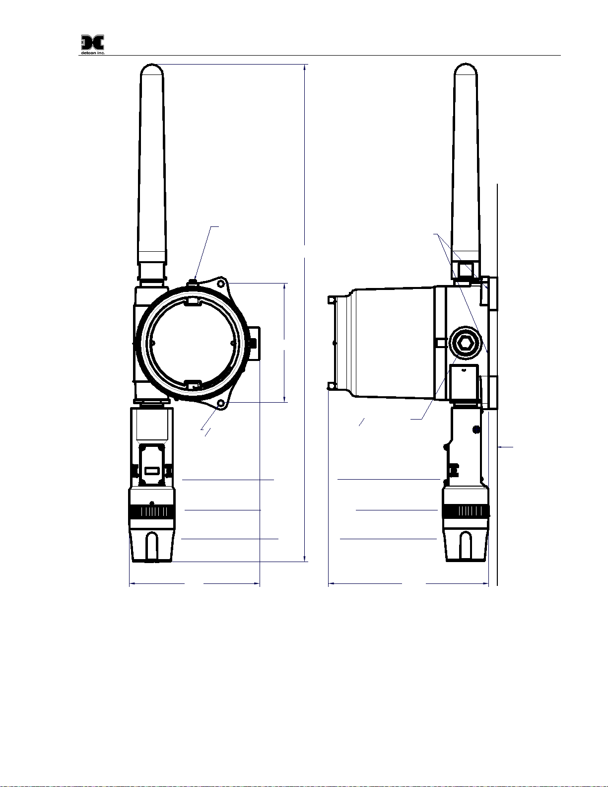
2.4 Sensor Mounting
The CXT-IR should be vertically oriented so that the sensor points straight downward (Figure 12). The
explosion-proof enclosure or junction box is typically mounted on a wall or pole. Detcon provides a selection of
standard junction boxes in both Aluminum and Stainless Steel.
NOTE: If wall mounting without a mounting plate, make sure to use at least 0.5” spacers
underneath the Detcon Aluminum Junction-Box’s 1/4” mounting holes to
move the sensor
assembly away from the wall and allow access clearance to the sensor assembly.
NOTE: Do not use Teflon Tape or any other type of Pipe Thread material on the ¾” threads
unless the sensor is mounted in a severe or harsh environment. Metal-on-metal contact must be
maintained to provide a solid electrical ground path. If Teflon Tape is used the Sensor must be
externally grounded using a ground strap.
When mounting on a pole, secure the Junction Box to a suitable mounting plate and attach the mounting plate
to the pole using U-Bolts. (Pole-Mounting brackets for Detcon Junction Boxes are available separately.)
Model CXT-IR
CXT-IR Instruction Manual Rev. 2.1 Page 13 of 48
8-32 tapped
ground point
7.45"
34
NPT Port
9.5"
Wall
(or other
mounting surface)
Splash Guard Adapter
Splash Guard
ITM Assembly
23" Typ.
Use spacers to move
sensor assembly away
from wall at least 0.5".
Spacer
14
" mounting
holes
Spacer
5.5"
Figure 12 CXT-IR Sensor with D or Smart Battery Pack Mounting Dimensions
Model CXT-IR
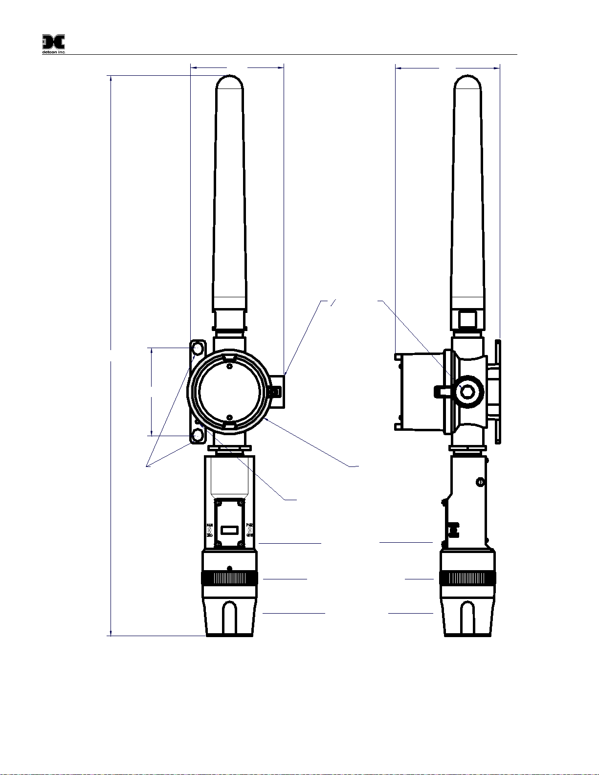
CXT-IR Instruction Manual Rev. 2.1 Page 14 of 48
6-32 tapped
ground point
4.1"
34
NPT Port
3.64"
Ø0.4 X 0.475"
mounting
holes
Splash Guard Adapter
Splash Guard
ITM Assembly
3.45"
22"Typ.
Mini Condulet with
Battery Holder and
Batteries
Figure 13 CXT-IR Sensor with C-Cell Batteries

Model CXT-IR
CXT-IR Instruction Manual Rev. 2.1 Page 15 of 48
2.5 Electrical Installation
The CXT is designed to be battery operated, and normally will not have external cabling or wiring. If the sensor
requires external wiring, the sensor assembly should be installed in accordance with local electrical codes. Proper
electrical installation of the gas sensor is critical for conformance to electrical codes and to avoid damage due
to water leakage.
If a conduit run exists, a drain should be incorporated. The drain allows H2O condensation inside the conduit
run to safely drain away from the sensor assembly. The electrical seal fitting is required to meet the National
Electrical Code per NEC Article 500-3d (or Canadian Electrical Code Handbook Part 1 Section 18-154).
Requirements for locations of electrical seals are covered under NEC Article 501-5. Electrical seals also act as
a secondary seal to prevent water from entering the wiring terminal enclosure. However, they are not designed
to provide an absolute watertight seal, especially when used in the vertical orientation.
NOTE: The Detcon Warranty does not cover water damage resulting from water leaking into
the enclosure.
NOTE: Any unused ports should be blocked with suitable ¾” male NPT plugs. Detcon supplies
one ¾” NPT male plug with each J-box enclosure. If connections are other than ¾” NPT, use
an appropriate male plug of like construction material.
CAUTION Do not apply System power to the sensor until all wiring is properly terminated
(2.6 Initial Start Up).
NOTE: For products utilizing the aluminum junction box option, the conduit seal shall be placed
at the entry to the junction box. For products utilizing the stainless steel junction box option, the
conduit seal shall be placed within 18” of the enclosure. Crouse Hinds type EYS2, EYD2 or
equivalent are suitable for this purpose.
2.5.1 Applying Power to the Unit
CAUTION
A 24V solar panel is the most common option for supplying external power. A solar
panel will recharge the Detcon Smart Battery Pack. DO NOT CHARGE IN A
HAZARDOUS LOCATION. It CANNOT be used with the C-cells or D-cells. A
24V input with the C-cells or D-cells will damage the cells.
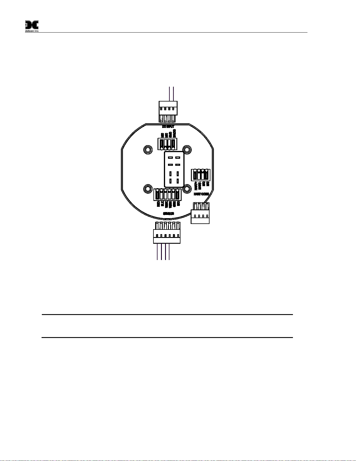
1. Remove the junction box cover
2. If external power is to be applied to the unit, connect the incoming 24V to the Connector labeled ‘DC
INPUT’. Connect 24V to the terminal labeled ‘24VDC’ and Return to the terminal labeled “GND”. The
Battery Bracket will need to be removed in order to access the connector.
3. Install the batteries:
NOTE
The safety approvals require removing entire sensor assembly to a non-hazardous area before
installing or changing out the batteries or battery pack.
a) For units utilizing the 12V Smart Battery Pack or the D-Size Battery Holder/pack, remove the
battery cover by unscrewing the top screws and moving the battery cover out of the way. Plug the
battery pack into the Terminal Board. Power will be applied, and the unit will proceed to power up
(Section 2.6). The battery Packs will only plug in in one orientation. Replace the Battery Cover
and tighten the two screws down to secure the battery pack in place.
Model CXT-IR
CXT-IR Instruction Manual Rev. 2.1 Page 16 of 48
b) If the unit utilizes the “C” sized lithium 3.6V batteries and battery holder, install the batteries being
careful to install the batteries properly. Power will be applied, and the unit will proceed to power
up (Section 2.6).
Black
Wht/Blk
Wht/Brn
Red
To Sensor
24V Power
To External
Return
24VDC
Figure 14 Terminal Interconnect for Smart Battery Pack
4. Replace the junction box cover after Initial Start Up. Ensure that the cover is screwed down completely and
that the Allen Head screw is tightened down to secure the cover in place.
NOTE: A 6-32 or 8-32 threaded exterior ground point is provided on most junction boxes for an
external ground. If the Sensor Assembly is not mechanically grounded, an external ground strap
must be used to ensure that the sensor is electrically grounded.
Table of contents
Other Detcon Accessories manuals

Detcon
Detcon PI-700 User manual

Detcon
Detcon SmartWireless CX User manual

Detcon
Detcon DM-700 User manual

Detcon
Detcon FP-700 User manual

Detcon
Detcon TP-524D User manual

Detcon
Detcon DM-100 Series User manual

Detcon
Detcon TP-700 User manual

Detcon
Detcon FP-524D User manual

Detcon
Detcon DM-500IS OLED Series User manual

Detcon
Detcon IR-700 User manual


