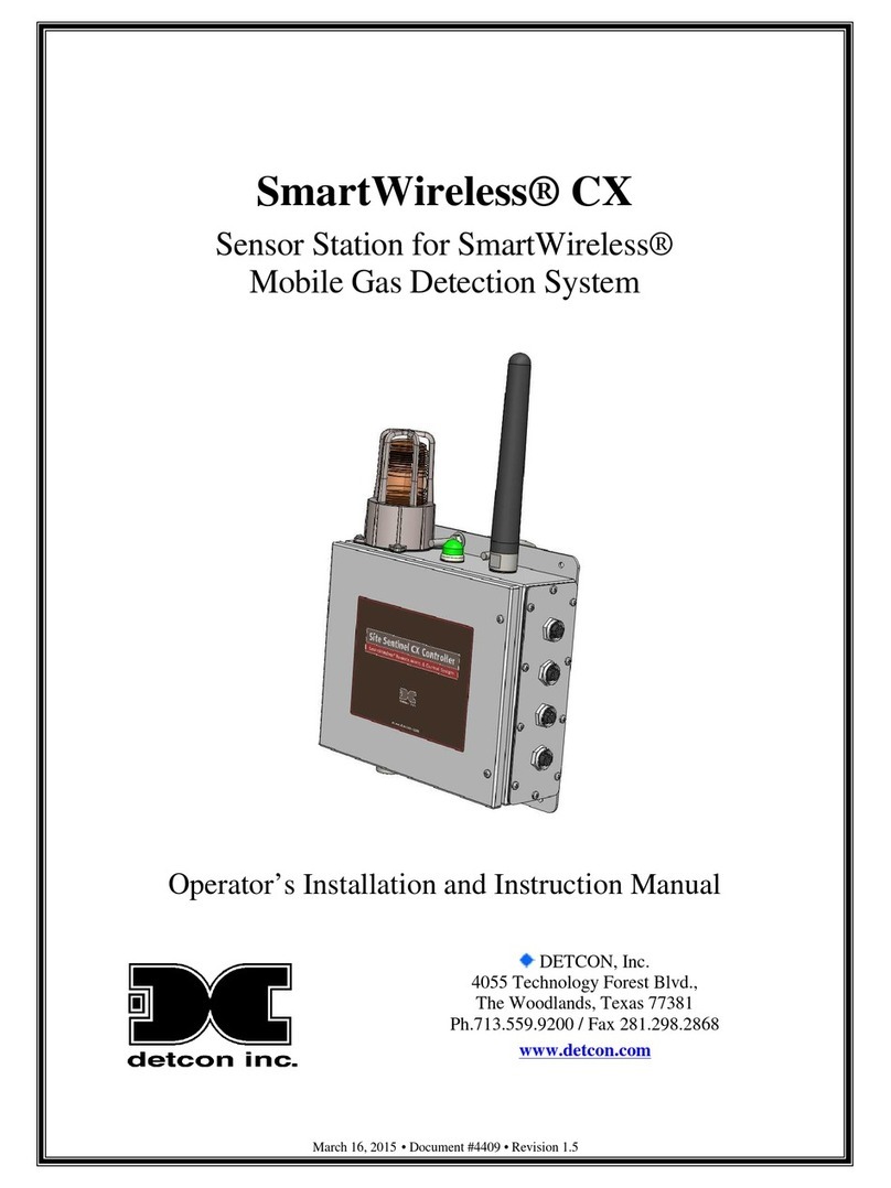
Detcon PI-700 User manual

Model PI-700
Model PI-700 ii
This page left intentionally blank

Model PI-700
Model PI-700 iii
Table of Contents
1. Introduction ..................................................................................................................................................1
1.1 Description.......................................................................................................................................... 1
1.2 Sensor Electronics Design .................................................................................................................. 1
1.3 Modular Mechanical Design............................................................................................................... 2
1.4 Intelligent Plug-in PID Gas Sensor..................................................................................................... 3
2. Installation....................................................................................................................................................4
2.1 ATEX Operational Guidelines for Safe Use....................................................................................... 4
2.2 Sensor Placement................................................................................................................................ 5
2.3 Sensor Contaminants and Interference ............................................................................................... 6
2.4 Mounting Installation.......................................................................................................................... 6
2.5 Electrical Installation.......................................................................................................................... 9
2.6 Field Wiring...................................................................................................................................... 10
2.7 Initial Start Up................................................................................................................................... 12
3. Operation....................................................................................................................................................14
3.1 Programming Magnet Operating Instructions................................................................................... 14
3.2 Operator Interface............................................................................................................................. 15
3.3 Normal Operation ............................................................................................................................. 16
3.4 Calibration Mode.............................................................................................................................. 17
3.4.1 AutoZero....................................................................................................................................... 17
3.4.2 AutoSpan...................................................................................................................................... 17
3.5 Program Mode .................................................................................................................................. 20
3.5.1 View Sensor Status....................................................................................................................... 20
3.5.2 Set AutoSpan Level...................................................................................................................... 22
3.5.3 Set Serial ID ................................................................................................................................. 23
3.5.4 Set Range...................................................................................................................................... 23
3.5.5 Set Gas Factor............................................................................................................................... 24
3.5.6 Set Zero Offset.............................................................................................................................. 24
3.5.7 Signal Output Check..................................................................................................................... 25
3.5.8 Restore Factory Defaults .............................................................................................................. 25
3.6 Program Features .............................................................................................................................. 26
3.6.1 Operational Features..................................................................................................................... 26
3.6.2 Fault Diagnostic/Failsafe Features ............................................................................................... 26
4. RS-485 Modbus™ Protocol .......................................................................................................................29
Content Description.............................................................................................................................................29
5. Service and Maintenance............................................................................................................................31
5.1 PID Plug-In Sensor Maintenance...................................................................................................... 31
5.2 Replacement of Intelligent Plug-in Sensor ....................................................................................... 38
5.3 Replacement of ITM......................................................................................................................... 39
5.4 Replacement of PI-700 Sensor Assembly......................................................................................... 39
6. Troubleshooting Guide...............................................................................................................................41
7. Customer Support and Service Policy........................................................................................................44
8. PI-700 Sensor Warranty .............................................................................................................................45
9. Appendix ....................................................................................................................................................46
9.1 Specifications.................................................................................................................................... 46
9.2 Gas Reference Table......................................................................................................................... 48
9.3 Spare Parts, Sensor Accessories, Calibration Equipment................................................................. 55
10. Revision History.....................................................................................................................................56

Model PI-700
Model PI-700 iv
Table of Figures
Figure 1 Typical Sensor Cell................................................................................................................................ 1
Figure 2 ITM Circuit Functional Block Diagram................................................................................................. 2
Figure 3 Sensor Assembly Front View ................................................................................................................ 2
Figure 4 Sensor Assembly Breakaway................................................................................................................ 3
Figure 5 Intelligent Plug-in Sensor....................................................................................................................... 3
Figure 6 PI-700 ATEX Approval Label............................................................................................................... 4
Figure 7 Outline and Mounting Dimensions (Sensor Assembly only)................................................................. 7
Figure 8 Outline and Mounting Dimensions (Stainless Steel Junction Box)....................................................... 7
Figure 9 Outline and Mounting Dimensions (Aluminum Junction Box)............................................................. 8
Figure 10 Outline and Mounting Dimensions (Mini Stainless Steel Junction Box) ............................................ 8
Figure 11 Typical Installation ............................................................................................................................ 10
Figure 12 Sensor Wire Connections................................................................................................................... 11
Figure 13 Magnetic Programming Tool............................................................................................................. 14
Figure 14 Magnetic Programming Switches..................................................................................................... 14
Figure 15 PI-700 Software Flowchart................................................................................................................ 16
Figure 16 UV Lamp Aging Expectation ............................................................................................................ 31
Figure 17 Splashguard Adapter with Integral Filter........................................................................................... 32
Figure 18 Plug-in sensor with Moisture control packet ..................................................................................... 32
Figure 19 Sensor Cell Parts................................................................................................................................ 33
Figure 20 Removal of Filter Cap........................................................................................................................ 33
Figure 21 Removal of Filter Media.................................................................................................................... 34
Figure 22 Removal of Spacer............................................................................................................................. 34
Figure 23 Removal of Cell Assembly................................................................................................................ 34
Figure 24 Removal of Lamp .............................................................................................................................. 35
Figure 25 Lamp cleaning.................................................................................................................................... 35
Figure 26 Polishing the Lamp............................................................................................................................ 35
Figure 27 Lamp installation ............................................................................................................................... 36
Figure 28 Lamp seating...................................................................................................................................... 36
Figure 29 Cell Assembly installation................................................................................................................. 36
Figure 30 Spacer installation.............................................................................................................................. 37
Figure 31 Installing Filter Media........................................................................................................................ 37
Figure 32 Replacing the Cap.............................................................................................................................. 37
Figure 33 Sensor Assembly................................................................................................................................ 38
Figure 34 Sensor Cell and ITM Mating ............................................................................................................. 38
Figure 35 Sensor Cell and ITM Mating ............................................................................................................. 41
List of Tables
Table 1 Wire Gauge vs. Distance....................................................................................................................... 10
Table 2 Maximum and Minimum AutoSpan Settings........................................................................................ 22
Table 3 Modbus™ Registers.............................................................................................................................. 29
Table 4 Modbus™ Special Registers ................................................................................................................. 30
Table 5 Gas Factor Table ................................................................................................................................... 48
Shipping Address: 4055 Technology Forest Blvd., The Woodlands Texas 77381
Mailing Address: P.O. Box 8067, The Woodlands Texas 77387-8067
Phone: 888.367.4286, 281.367.4100 • Fax: 281.292.2860 • www.detcon.com • sales@detcon.com

Model PI-700
PI-700 Instruction Manual Rev. 3.2 Page 1 of 58
1. Introduction
1.1 Description
Detcon Model PI-700 VOC gas sensors are non-intrusive “Smart” sensors designed
to detect and monitor a wide range of VOC and Toxic gasses in air. Ranges of
detection for target gasses are from 0-1ppm up to 0-5,000ppm. The sensor features
an LED display of current reading, fault and calibration status. The Sensor is
equipped with standard analog 4-20mA and Modbus™ RS-485 outputs. A primary
feature of the sensor is its method of automatic calibration, which guides the user
through each step via fully scripted instructions displayed on the LED display.
The microprocessor-supervised electronics are packaged in an encapsulated module
and housed in an explosion proof casting, called the ITM (Intelligent Transmitter
Module). The ITM includes a four character alpha/numeric LED used to display
sensor readings, and the sensor’s menu driven features when the hand-held
programming magnet is used.
Sensor Technology
The sensors are based on plug-in replaceable miniature PID (Photo-Ionization Detector) sensor technology. The
sensor is sensitive to ambient gases that have ionization potentials of < 10.6eV, making it highly sensitive but
extremely non-specific. The sensor responds to most toxic VOC compounds and many other toxic gases as well.
The sensor is comprised of a UV lamp covered by a specific optical filter which projects only radiation in the
10.6eV range. Target gases that diffuse into the sensor chamber with ionization potentials of < 10.6eV, are
ionized by the radiation and give up free electrons. The free electrons are captured by the high voltage collection
grid and provide a current that is directly proportional to the concentration of the target gas.
Figure 1 Typical Sensor Cell
1.2 Sensor Electronics Design
Intelligent Transmitter Module
The PI-700 Intelligent Transmitter Module (ITM) is a fully encapsulated microprocessor-based package that is
universal in design and will accept any Detcon intelligent plug-in PID gas sensor. The ITM design uses an
internal intrinsically safe barrier circuit that lifts the requirement for use of flame arrestors to achieve Class 1,
Division 1 (Zone1) area classification. This facilitates fast response times and improved calibration repeatability
on strongly absorbing gas types. The ITM circuit functions include extensive I/O circuit protection, on-board
power supplies, internal intrinsically safe barrier circuit, microprocessor, LED display, magnetic programming
switches, a linear 4-20mA DC output, and a Modbus™ RS-485 output. Magnetic program switches located on
either side of the LED Display are activated via a hand-held magnetic programming tool, thus allowing non-
Table of contents
Other Detcon Accessories manuals
Detcon
Detcon IR-700 User manual
Detcon
Detcon TP-700 User manual

Detcon
Detcon MicroSafe TP-524C User manual
Detcon
Detcon FP-700 User manual
Detcon
Detcon CXT-IR User manual

Detcon
Detcon CXT-DM User manual
Detcon
Detcon TP-524D User manual

Detcon
Detcon DM-700 User manual
Detcon
Detcon FP-524D User manual
Detcon
Detcon DM-100 Series User manual

