Detcon FP-700 User manual
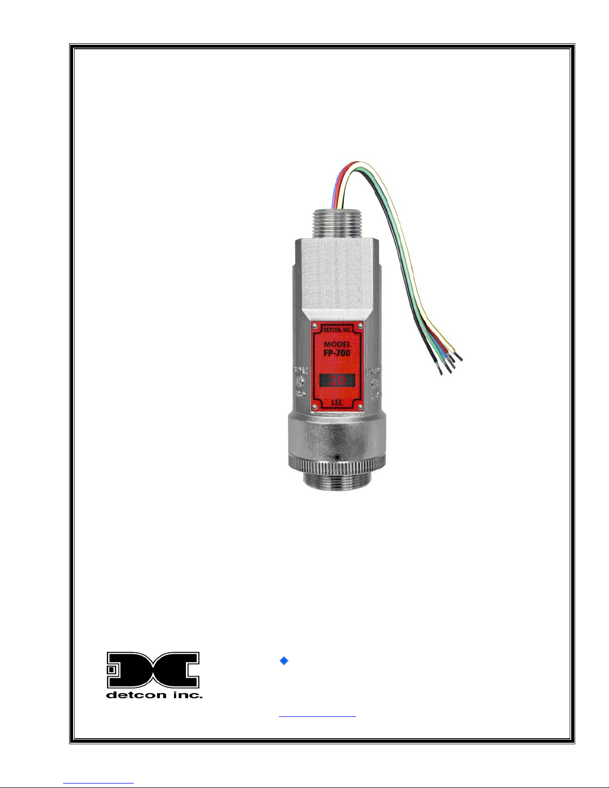
INSTRUCTION MANUAL
Detcon Model FP-700
FP-700 Combustible Gas Sensor
0-100% LEL
0-50% LEL
DETCON, Inc.
4055 Technology Forest Blvd.,
The Woodlands, Texas 77381
Ph.281.367.4100 / Fax 281.298.2868
www.detcon.com
June 05, 2018 • Document #3168 • Revision 5.1

Model FP-700
Model FP-700 ii
This page left intentionally blank

Model FP-700
Model FP-700 iii
Table of Contents
1. Introduction ..................................................................................................................................................1
1.1 Description.......................................................................................................................................... 1
1.2 Sensor Electronics Design .................................................................................................................. 2
1.3 Modular Mechanical Design............................................................................................................... 3
1.4 Plug-in Replaceable Sensor ................................................................................................................ 4
2. Installation....................................................................................................................................................5
2.1 Operational Guidelines for Safe Use – HazLoc Certifications........................................................... 5
2.2 Sensor Placement................................................................................................................................ 6
2.3 Sensor Contaminants and Interference ............................................................................................... 7
2.4 Mounting Installation.......................................................................................................................... 8
2.5 Electrical Installation........................................................................................................................ 10
2.6 Field Wiring...................................................................................................................................... 11
2.7 Initial Start Up................................................................................................................................... 13
3. Operation....................................................................................................................................................15
3.1 Programming Magnet Operating Instructions................................................................................... 15
3.2 Operator Interface............................................................................................................................. 16
3.3 Normal Operation ............................................................................................................................. 17
3.4 Calibration Mode (AutoZero and AutoSpan) ................................................................................... 18
3.4.1 AutoZero....................................................................................................................................... 18
3.4.2 AutoSpan...................................................................................................................................... 18
3.5 Program Mode .................................................................................................................................. 20
3.5.1 Navigating Program Mode ........................................................................................................... 21
3.5.2 View Sensor Status....................................................................................................................... 21
3.5.3 Set AutoSpan Level...................................................................................................................... 22
3.5.4 Set Gas Factor............................................................................................................................... 23
3.5.5 Set Cal Factor ............................................................................................................................... 24
3.5.6 Set Serial ID ................................................................................................................................. 25
3.5.7 Set Bridge Voltage........................................................................................................................ 25
3.5.8 Signal Output Check..................................................................................................................... 26
3.5.9 Restore Factory Defaults .............................................................................................................. 26
3.6 Program Features .............................................................................................................................. 27
3.6.1 Operational Features..................................................................................................................... 27
3.6.2 Fault Diagnostic/Failsafe Features ............................................................................................... 28
4. RS-485 Modbus™ Protocol .......................................................................................................................30
Content Description.............................................................................................................................................30
5. Service and Maintenance............................................................................................................................32
5.1 Calibration Frequency....................................................................................................................... 32
5.2 Visual Inspection .............................................................................................................................. 32
5.3 Condensation Prevention Packet....................................................................................................... 32
5.4 Replacement of Plug-in Combustible Gas Sensor............................................................................ 33
5.5 Replacement of ITM......................................................................................................................... 33
5.6 Replacement of FP-700 Sensor Assembly........................................................................................ 34
6. Troubleshooting Guide...............................................................................................................................35
7. Customer Support and Service Policy........................................................................................................38
8. FP-700 Sensor Warranty ............................................................................................................................39
9. Appendix ....................................................................................................................................................40
9.1 Specifications.................................................................................................................................... 40
9.2 Spare Parts, Sensor Accessories, Calibration Equipment................................................................. 43
10. Revision Log..........................................................................................................................................44

Model FP-700
Model FP-700 iv
Table of Figures
Figure 1 Sensor Cell Construction ....................................................................................................................... 1
Figure 2 Wheatstone Bridge................................................................................................................................. 2
Figure 3 Response Curves.................................................................................................................................... 2
Figure 4 ITM Circuit Functional Block Diagram................................................................................................. 3
Figure 5 Sensor Assembly Front View ................................................................................................................ 3
Figure 6 Sensor Assembly Breakaway................................................................................................................. 4
Figure 7 FP Replaceable Sensor Cell................................................................................................................... 4
Figure 8 HazLoc Certification Approval Label.................................................................................................... 5
Figure 9 Outline and Mounting Dimensions (Sensor Assembly only)................................................................. 8
Figure 10 Outline and Mounting Dimensions (Stainless Steel Junction Box)..................................................... 9
Figure 11 Outline and Mounting Dimensions (Aluminum Junction Box)........................................................... 9
Figure 12 Outline and Mounting Dimensions (Mini Stainless Steel Junction Box) .......................................... 10
Figure 13 Typical Installation ............................................................................................................................ 11
Figure 14 Sensor Wire Connections................................................................................................................... 13
Figure 15 Magnetic Programming Tool............................................................................................................. 15
Figure 16 Magnetic Programming Switches...................................................................................................... 15
Figure 17 FP-700 Software Flowchart............................................................................................................... 17
Figure 18 Sensor Assembly................................................................................................................................ 32
Figure 19 Plug-in Sensor (Bottom View)........................................................................................................... 35
List of Tables
Table 1 Wire Gauge vs. Distance....................................................................................................................... 12
Table 2 Gas/Cal Factors ..................................................................................................................................... 24
Table 3 Modbus™ Registers.............................................................................................................................. 30
Table 4 Modbus™ Special Registers ................................................................................................................. 31
Shipping Address: 4055 Technology Forest Blvd., The Woodlands Texas 77381
Mailing Address: P.O. Box 8067, The Woodlands Texas 77387-8067
Phone: 888.367.4286, 281.367.4100 • Fax: 281.292.2860 • www.detcon.com • sales@detcon.com
Model FP-700
FP-700 Instruction Manual Rev. 5.1 Page 1 of 46
1. Introduction
1.1 Description
Detcon Model FP-700 combustible gas sensors are non-intrusive “Smart” sensors
designed to detect and monitor combustible gases in air. Range of detection is 0-100%
LEL or 0-50% LEL. The sensor features an LED display of current reading, fault and
calibration status. The unit is equipped with standard analog 4-20mA and Modbus™ RS-
485 outputs. A primary feature of the sensor is its method of automatic calibration, which
guides the user through each step via fully scripted instructions displayed on the LED
display.
The microprocessor-supervised electronics are packaged in an encapsulated module and
housed in an explosion proof casting. The unit includes a 4 character alpha/numeric LED
used to display sensor readings, and the sensor’s menu driven features when the hand-held
programming magnet is used.
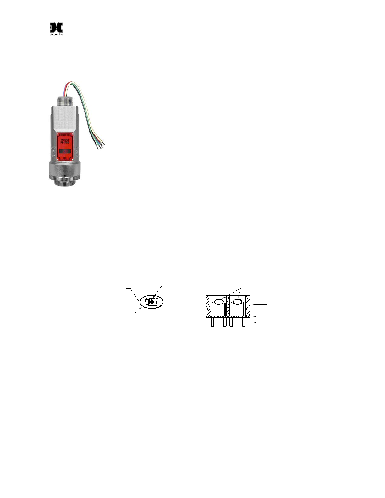
Catalytic Bead (Pellistor) Sensor Technology
The sensor technology is a poison-resistant catalytic bead type. Catalytic bead sensors show a strong response
to a long list of combustible gases. The sensor is supplied as a matched-pair of detector elements mounted in a
plug-in replaceable module. One bead is a catalytically active detector and the other is a non-active reference
detector. Each detector consists of a fine platinum wire coil embedded in aluminum oxide. A catalytic mixture
is applied to the active detector while the reference detector is treated so that oxidation of the gas does not occur.
The technique is referred to as non-selective and may be used to monitor most any combustible gas. Detcon
catalytic bead sensors are specifically designed to be resistant to poisons such as sulfides, chlorides, and
silicones. The sensors are characteristically stable and capable of providing reliable performance for periods
exceeding 5 years in most industrial environments.
Figure 1 Sensor Cell Construction
Principle of Operation
Method of detection is by diffusion/adsorption. Air and combustible gases pass through a sintered stainless steel
filter and contact the heated surface of both the active and reference detectors. The surface of the active detector
promotes oxidation of the combustible gas molecules while the reference detector has been treated not to support
this oxidation. The reference detector serves as a means to maintain zero stability over a wide range of
temperature and humidity.
When combustible gas molecules oxidize on the surface of the active detector, heat is generated, and the
resistance of the detector changes. Electronically, the detectors form part of a balanced bridge circuit. As the
active detector changes in resistance, the bridge circuit unbalances. This change in output is conditioned by the
amplifier circuitry, which is an integral part of the sensor design. The response and clearing characteristics of
the sensor are rapid and provide for the continuous and accurate monitoring of ambient air conditions.
Main Housing Insert
Printed Circuit Board
Gold Plated Pins
Platinum Wire
Construction
of Detector
Bead
Catalyst
Alumina Bead Catalytic Beads
Model FP-700
FP-700 Instruction Manual Rev. 5.1 Page 2 of 46
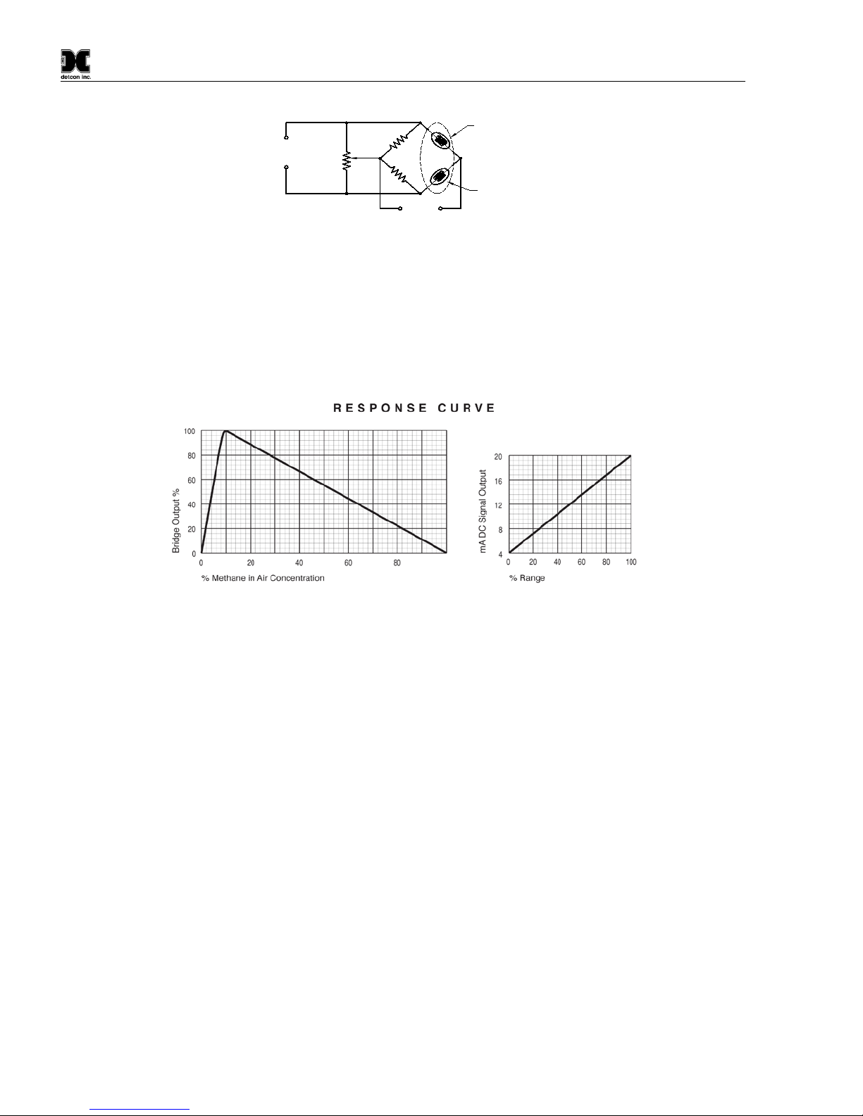
Figure 2 Wheatstone Bridge
Performance Characteristics
The detector elements maintain good sensitivity to combustible gas concentrations in the Lower Explosive Limit
(LEL) range, as shown in the response curves in Figure 3. However, for gas concentrations significantly above
the LEL range (100% LEL = 5% by volume Methane), the bridge output begins to decrease. Ambiguous
readings above the LEL range dictate that alarm control logic be of the latching type, wherein alarms are held
in the “ON” position until reset by operations personnel.
Figure 3 Response Curves
1.2 Sensor Electronics Design
Intelligent Sensor Module
The Intelligent Transmitter Module (ITM) is a fully encapsulated microprocessor-based package that accepts a
plug-in field replaceable combustible gas sensor. Circuit functions include extensive I/O circuit protection,
sensor pre-amplifier, bridge voltage (temperature) control, on-board power supplies, microprocessor, LED
display, magnetic programming switches, linear 4-20mA DC output, and Modbus™ RS-485 output. Magnetic
program switches located on either side of the LED Display are activated via a hand-held magnetic programming
tool, thus allowing non-intrusive operator interface with the ITM. Calibration can be accomplished without
declassifying the area. Electrical classifications are Class I, Division 1, Groups B C D, Class I, Zone 1, Group
IIB+H2and II 2G Ex d IIB+H2Gb.
Sensor
Cell
Zero
Adjust
Output
Input
Voltage
Compensator /
Reference Bead
Detector /
Active Bead
Model FP-700
FP-700 Instruction Manual Rev. 5.1 Page 3 of 46
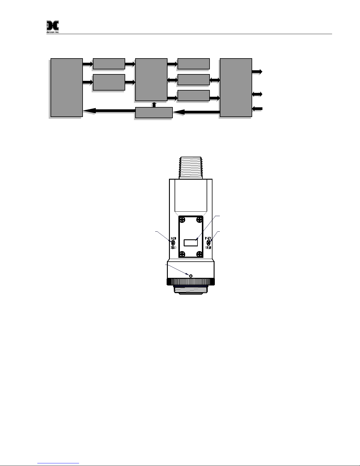
Figure 4 ITM Circuit Functional Block Diagram
Program Switch #1
LED Display
Program Switch #2
Splashguard Adapter
Lockdown Set-Screw
detcon inc.
LEL Sensor
MODEL
FP-700
Figure 5 Sensor Assembly Front View
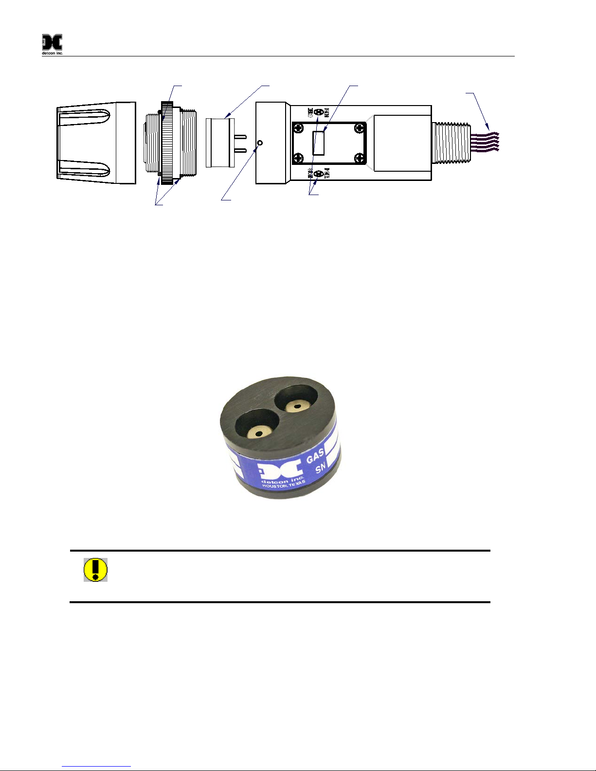
1.3 Modular Mechanical Design
The Model FP-700 Sensor Assembly is completely modular and made up of four parts (See Figure 6 for
Assembly Break-away):
1) FP-700 Intelligent Transmitter Module (ITM)
2) Field Replaceable Plug-in Combustible Gas Sensor
3) Model 700 Housing Bottom Assembly (contains the Housing Bottom, Flame Arrestor, Retaining Ring,
and rubber O-Rings)
4) Splash Guard.
NOTE: All metal components are constructed from electro-polished 316 Stainless Steel in order to maximize
corrosion resistance in harsh environments.
I/O
Circuit
Protection
RS-485
4-20mA
Display
Micro-
Processor
Temperature
Control
Pre-Amp
Analog 4-20mA Out
Modbus™ RS-485 Output
Power In
Power Supply
Plug-In
Sensor
Element
Model FP-700
FP-700 Instruction Manual Rev. 5.1 Page 4 of 46
Housing Bottom
Locking Set-Screw
Splash Guard
O-Rings
Intelligent Transmitter Module
(ITM) Microprocessor controlled
circuit encapsulated in an
explosion proof housing
Splashguard
Adapter Plug-In replaceable
H2S Sensor
Magnetic
Programming
Switches
Lens and LCD
Display Interconnect
Wiring
detcon inc.
LEL Sensor
MODEL
FP-700
Figure 6 Sensor Assembly Breakaway
1.4 Plug-in Replaceable Sensor
The Detcon combustible gas sensor is a poison-resistant and field proven design. It is packaged as true plug-in
replaceable type sensor with over-sized gold-plated connections that eliminate corrosion problems. It can be
accessed and replaced in the field very easily by releasing the locking screw and unthreading the housing bottom.
The Detcon combustible gassensor has an infinite shelf life, and is supported by a 2-year warranty. The expected
service life is 3-5 years.
Figure 7 FP Replaceable Sensor Cell
Caution: Hazardous areas must be declassified before removing and/or replacing the
plug in sensor
Model FP-700
FP-700 Instruction Manual Rev. 5.1 Page 5 of 46
2. Installation
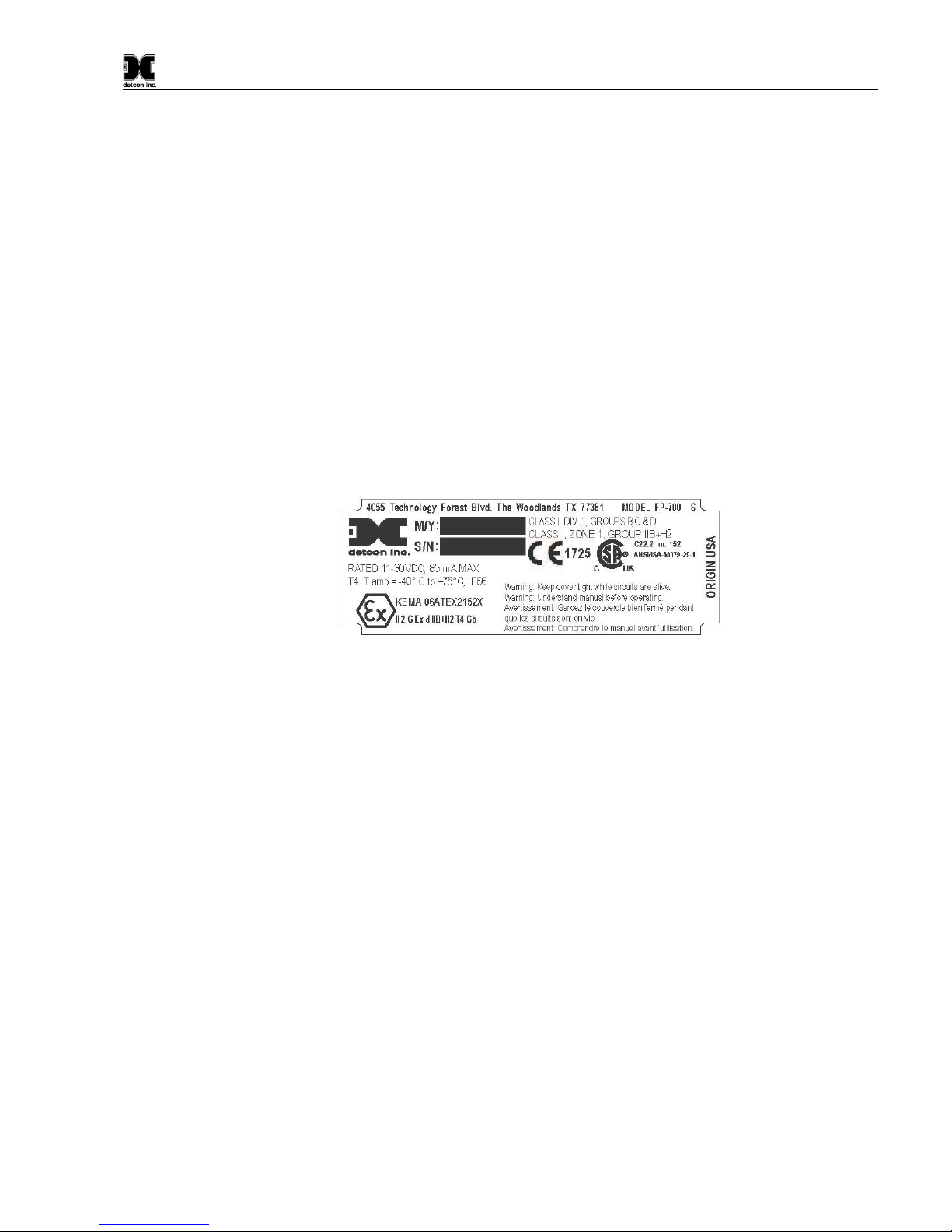
2.1 Operational Guidelines for Safe Use – HazLoc Certifications
1. It is recommended for end-users to read and reference the procedures described in IEC 60079-29-2 for
guidance on the proper installation, operation, and servicing of this type of combustible gas detectors.
2. Install sensor only in areas with classifications matching with those described on the ATEX approval
label. Follow all warnings listed on the label.
3. Detector is performance tested to ANSI/UL 12.13.01:2013 Performance Requirements of Detectors for
Flammable Gases. Performance Testing was completed by CSA Group on March 28, 2018. This Model
FP-700 detector is performance tested only for methane gas measurement in the 0-100 % LEL (0-5%
by volume) range and with use of Accessory PN 613-120000-700 Sensor Splashguard with integral Cal
Port. There are no special conditions for use other than what is specified here in Section 2.1 of
Instruction Manual.
Figure 8 HazLoc Certification Approval Label
4. Ensure that the sensor is properly threaded into a suitable flameproof rated junction box with a
downward pointing female ¾” NPT threaded connection. The sensor should be threaded up at least 5
full turns until tight, with the LED display facing forward (+/-15°). Minimize use of Teflon Tape, or
any type of non-conductive pipe thread coating on the NPT threaded connection.
5. A good ground connection should be verified between the sensor’s metal enclosure and the junction
box. If a good ground connection is not made, the sensor can be grounded to the junction box using the
sensor’s external ground lug. Also verify a good ground connection between the junction box and earth
ground. Installer shall use ring terminal to make connection to earth ground to be secured by screw and
lock washer on sensor housing.
6. Ensure that the Housing Bottom and plug-in sensor are installed during operation. The Housing Bottom
should be threaded tightly to the Intelligent Transmitter Module. The locking setscrew (M3 x 0.6 6g6h
Stainless Steel Allen set screw cup point with yield strength of greater than 40,000 PSI, typical 80,000
PSI) should then be tightened down to keep the Housing Bottom from being inadvertently removed or
from becoming loose under vibration. The locking setscrew ensures that Housing Bottom is only
removable by authorized personnel with the use of special tools. A M1.5 Allen Wrench is required. If
screw requires replacement, only an identical screw may be used.
7. Removal of the Housing Bottom violates the Ex d protection method and hence power must be removed
from the sensor prior to its safe removal.

Model FP-700
FP-700 Instruction Manual Rev. 5.1 Page 6 of 46
8. The screws holding down the retaining plate label are special fasteners of type Stainless Steel Phillips
Pan-head Machine screw, M3 x 0.5, 6g6h having yield strength of greater than 40,000 PSI, typical
80,000 PSI. If screw requires replacement, only an identical screw may be used.
9. Proper precautions should be taken during installation and maintenance to avoid the build-up of static
charge on the plastic components of the sensor. These include the splashguard and splashguard adapter.
10. Do not operate the sensor outside of the stated operating temperature limits.
11. Do not operate the sensor outside the stated operating limits for voltage supply.
12. These sensors meet EN60079-0:2012:A1:2013, EN60079-1:2007.
2.2 Sensor Placement
Selection of sensor location is critical to the overall safe performance of the product. Seven factors play an
important role in selection of sensor locations:
(1) Density of the gas to be detected
(2) Most probable leak sources within the industrial process
(3) Ventilation or prevailing wind conditions
(4) Personnel exposure.
(5) Maintenance access.
(6) Personal Exposure.
(7) Oxygen is required in the background gas
Density
Placement of sensors relative to the density of the target gas is such that sensors for the detection of heavier than
air gases should be located within 4 feet of grade as these heavy gases will tend to settle in low lying areas. For
gases lighter than air, sensor placement should be 4-8 feet above grade in open areas or in pitched areas of
enclosed spaces.
NOTE: Methane and Hydrogen are lighter than air. Most other combustible gases are heavier
than air. Compare the molecular weight, density, or specific gravity of the target gas(es) with
that of air to determine appropriate placement.
Leak Sources
The most probable leak sources within an industrial process include flanges, valves, and tubing connections of
the sealed type where seals may either fail or wear. Other leak sources are best determined by facility engineers
with experience in similar processes.
Ventilation
Normal ventilation or prevailing wind conditions can dictate efficient location of gas sensors in a manner where
the migration of gas clouds is quickly detected.
Personnel Exposure
The undetected migration of gas clouds should not be allowed to approach concentrated personnel areas such as
control rooms, maintenance or warehouse buildings. A more general and applicable thought toward selecting
sensor location is combining leak source and perimeter protection in the best possible configuration.

Model FP-700
FP-700 Instruction Manual Rev. 5.1 Page 7 of 46
Maintenance Access
Consideration should be given to providing easy access for maintenance personnel. Consideration should also
be given to the consequences of close proximity to contaminants that may foul the sensor prematurely.
NOTE: In all installations the gas sensor should point straight down, refer to Figure 13.
Improper sensor orientation may result in false readings and permanent sensor damage.
O2 in Sample Gas Background (Required)
CAUTION:Oxygen gas in the background is required for proper operation. The sensor will not perform as
specified if there are not normal levels of ambient Oxygen (~ 20.9% O2) present in the sample gas or
measurement environment. If there is zero O2 in the background, the sensor will not respond to combustible
gas at all. If there is somewhat less than 20.9% O2 available, then the sensor will read low.
Additional Placement Considerations
The sensor should not be positioned where it may be sprayed or coated with surface contaminating substances.
Painting sensor assemblies is prohibited.
Although the sensor is designed to be RFI resistant, it should not be mounted in close proximity to high-powered
radio transmitters or similar RFI generating equipment.
When possible in an area void of high wind, accumulating dust, rain or splashing from hose spray, direct steam
releases, and continuous vibration. If the sensor cannot be mounted away from these conditions then make sure
the Detcon Harsh Environment Splashguard accessory is used.
Do not mount in locations where temperatures will exceed the operating temperature limits of the sensor. Where
direct sunlight leads to exceeding the high temperature-operating limit, use a sunshade to help reduce
temperature.
2.3 Sensor Contaminants and Interference
Detcon combustible gas sensors may be adversely affected by exposure to certain airborne substances. Loss of
sensitivity or corrosion may be gradual if such materials are present in sufficient concentrations.
The performance of the detector elements may be temporarily impaired during operation in the presence of
substances described as inhibitors. Inhibitors are usually volatile substances containing halogen compounds.
Inhibitors include halide compounds such as Cl2, ClO2, F2, HF, HCl, Br2, vinyl chloride, and methyl chloride.
Inhibition is typically a temporary effect and the detectors generally recover after short periods of operation back
in clean air.
Some background gases may act as poisoning agents and have a more damaging effect on the sensor. Although
the sensor is designed to be poison resistant, it does have physical limits. Poisoning gases deactivate the active
detector’s catalytic ability and cause a permanent reduction in the span sensitivity. Examples of typical poisons
are: silicone oils and greases, siloxanes (HMDS), H2S, anti-knock petrol additives, and phosphate esters.
Activated carbon filters can be used to provide additional protection from poisoning in most cases.
The presence of such inhibitors and poisons in an area does not preclude the use of this sensor technology,
although it is likely that the sensor lifetime will be shorter as a result. Use of this sensor in these environments
may require more frequent calibration checks to ensure safe system performance.
Model FP-700
FP-700 Instruction Manual Rev. 5.1 Page 8 of 46
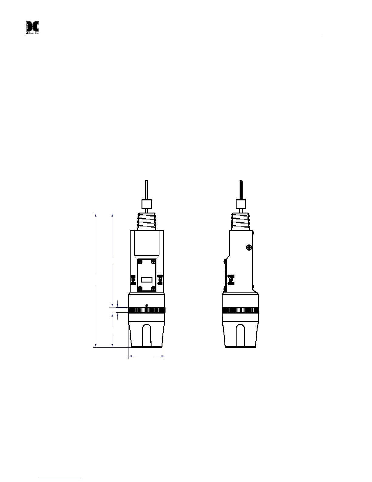
2.4 Mounting Installation
The FP-700 sensor assembly is designed to be threaded into a ¾” Female NPT fitting of a standard cast metal,
Explosion-Proof Enclosure or Junction Box. Thread the sensor up until tight (5 turns is typically expected) and
until the display is pointed in the direction that sensor will normally be viewed and accessed.
The FP-700 should be vertically oriented so that the sensor points straight downward. The explosion-proof
enclosure or junction box would then typically be mounted on a wall or pole. Detcon provides a standard
selection of junction boxes available as sensor accessories (See Figures 9, 10, 11, and 12 below), but any
appropriately rated enclosure with a downward facing ¾” NPT female connection will suffice.
When mounting on a wall, it is recommended to use a 0.25”-0.5” spacer underneath the mounting ears of the
Detcon standard J-Box to offset the sensor assembly from the wall and create open access around the sensor
assembly. Spacing requirements for other junction boxes may vary.
When mounting on a pole, secure the Junction Box to a suitable mounting plate and attach the mounting plate
to the pole using U-Bolts. (Pole-Mounting brackets for Detcon J-box accessories are available separately.)
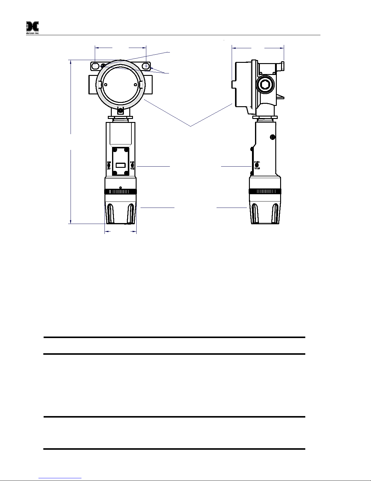
Male 3/4" NPT Threads
Sensor Assembly
Splash Guard
2.125"
7.8"
Typ.
Ferrite Cylinder
Sensor Wires
2"
0.3"
5.48"
detcon inc.
LEL Sensor
MODEL
FP-700
Figure 9Outline and Mounting Dimensions (Sensor Assembly only)
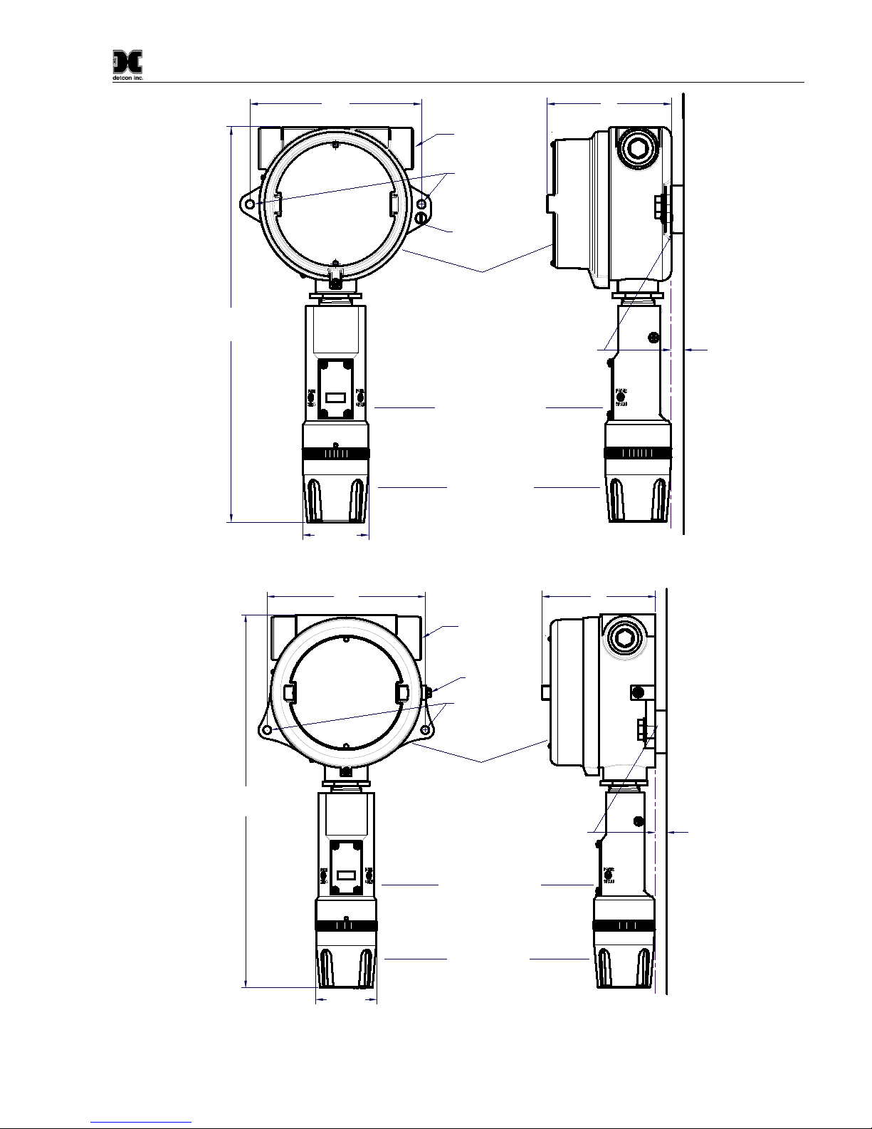
Model FP-700
FP-700 Instruction Manual Rev. 5.1 Page 9 of 46
4"
3/4" NPT
Explosion Proof Enclosure
Junction-Box
Sensor Assembly
Splash Guard
(Detcon's SS Junction-Box shown)
2.125"
5.5"
12.5"
Typ.
Mounting
Bolt
Use Spacers to move the J-Box
and Sensor Assembly away
from the wall at least 0.25-0.5"
to allow access to Sensor.
Wall
(or other
mounting surface)
Ø0.265"
Spacer
Mounting Holes
8-32 Thread
Ground Point
detcon inc.
LEL Sensor
MODEL
FP-700
Figure 10 Outline and Mounting Dimensions (Stainless Steel Junction Box)
4"
3/4" NPT
Explosion Proof Enclosure
Junction-Box
Sensor Assembly
Splash Guard
(Detcon's Aluminum Junction-Box shown)
2.125"
5.5"
13"
Typ.
Mounting
Bolt
Use Spacers to move the J-Box
and Sensor Assembly away
from the wall at least 0.25-0.5"
to allow access to Sensor
Wall
(or other
mounting surface)
Ø0.265" x2
Spacer
Mounting Holes
8-32 Thread
Ground Point
detcon inc.
LEL Sensor
MODEL
FP-700
Figure 11 Outline and Mounting Dimensions (Aluminum Junction Box)
Model FP-700
FP-700 Instruction Manual Rev. 5.1 Page 10 of 46
3.5"
Explosion Proof Enclosure
Junction-Box
Sensor Assembly
Splash Guard
(Detcon's Mini SS Junction-Box shown)
2.125"
3.45"
11"
Typ.
Mounting Holes
8-32 Thread
Ground Point
Ø0.4" x .475"
detcon inc.
LEL Sensor
MODEL
FP-700
Figure 12 Outline and Mounting Dimensions (Mini Stainless Steel Junction Box)
2.5 Electrical Installation
The Sensor Assembly should be installed in accordance with local electrical codes. The sensor assemblies are
CSA/NRTL approved (US and Canada) for Class I, Division 1, Groups B, C, & D area classifications, and are
ATEX Approved for II 2G Ex d IIB+H2Gb area classifications.
Proper electrical installation of the gas sensor is critical for conformance to Electrical Codes and to avoid damage
due to water leakage. Refer to Figure 13 and Figure 14 for proper electrical installation.
NOTE: If a conduit run exits the secondary port, repeat the installation technique shown in
Figure 13.
In Figure 13, the drain allows H2O condensation inside the conduit run to safely drain away from the sensor
assembly. The electrical seal fitting is required to meet the National Electrical Code per NEC Article 500-3d
(or Canadian Electrical Code Handbook Part 1 Section 18-154). Requirements for locations of electrical seals
are covered under NEC Article 501-5. Electrical seals also act as a secondary seal to prevent water from entering
the wiring terminal enclosure. However, they are not designed to provide an absolute water-tight seal, especially
when used in the vertical orientation.
NOTE: For products utilizing the aluminumjunction box option, the conduit seal shall be placed
at the entry to the junction box (see Figure 13 as an example). For products utilizing the stainless
steel junction box option, the conduit seal shall be placed within 18” of the enclosure. Crouse
Hinds type EYS2, EYD2 or equivalent are suitable for this purpose.
Model FP-700
FP-700 Instruction Manual Rev. 5.1 Page 11 of 46
NOTE: The Detcon Warranty does not cover water damage resulting from water leaking into
the enclosure through the conduit connections. However, since the electronics are 100% epoxy
encapsulated, only the wire terminations could get wet. Moisture could cause abnormal
operation and possibly corrosion to the terminal connections, but permanent damage tothe sensor
would not be expected.
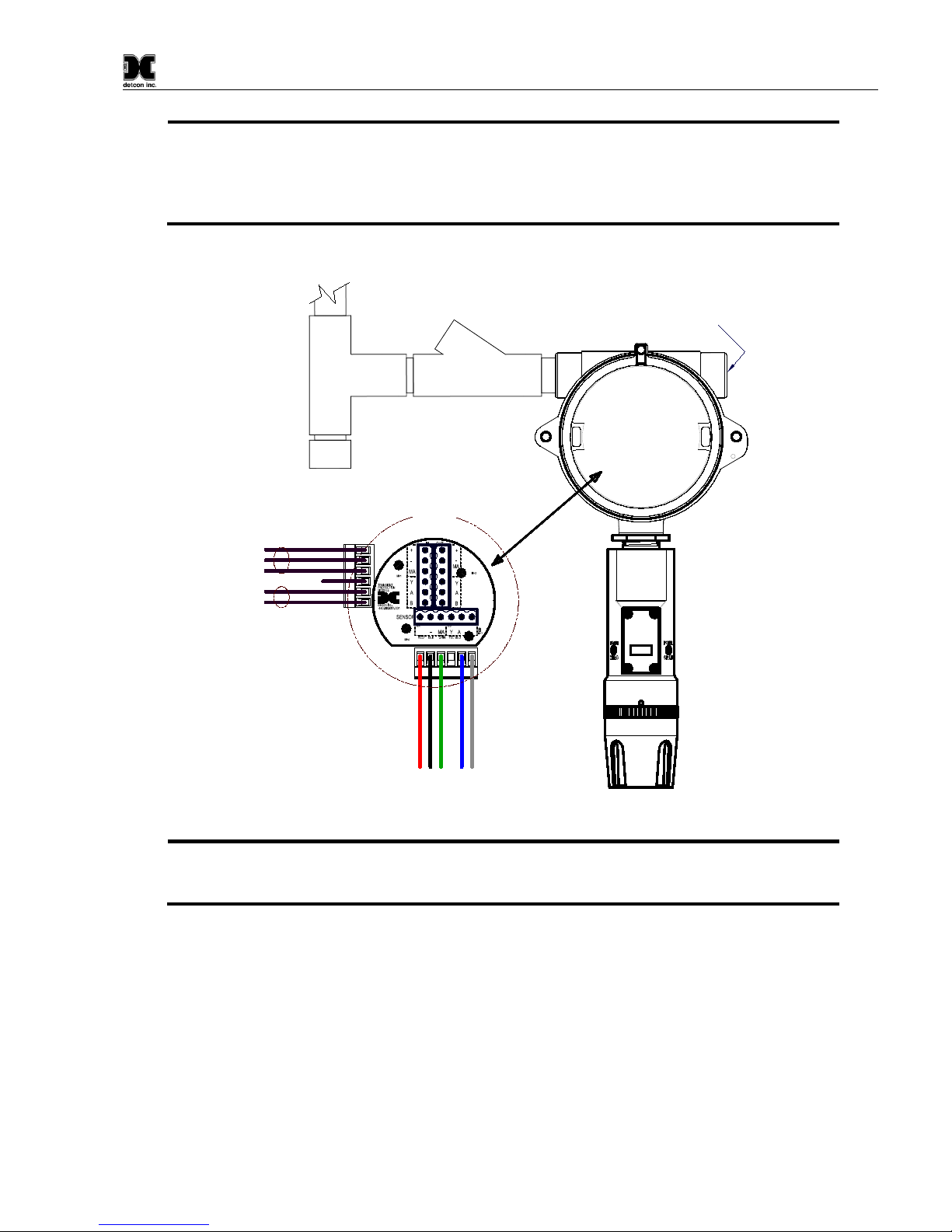
Plug any unused
ports
Explosion Proof
Housing
(J-Box)
Drain
FP-700
Sensor
Assembly
Conduit
"T" EYS Seal Fitting
(+)
mA
(-)
A(+)
B(-)
Wiring to
Sensor Assembly
Wht
Blu
Red
Grn
Blk
Explosion
Proof
Junction Box
(+)
mA
(-)
N/U
A(+)
B(-)
Customer
Supplied Wiring
Transient Protection Module
(TPM) P/N 500-003087-100
Mount TPM in Explosion
Proof Enclosure to ground
unit properly. Mount to
bottom of enclosure using
6-32 screws.
+
6-Pin Pheonix Plug
P/N 306-175705-100
detcon inc.
LEL Sensor
MODEL
FP-700
Figure 13 Typical Installation
NOTE: Any unused ports should be blocked with suitable ¾” male NPT plugs. Detcon supplies
one ¾” NPT male plug with their accessory J-box enclosures. If connections are other than ¾”
NPT, use an appropriate male plug of like construction material.
2.6 Field Wiring
Detcon Model FP-700 sensor assemblies require three conductor connections between power supplies and host
electronic controller’s 4-20mA output, and two conductor connections for the Modbus™ RS-485 serial interface.
Wiring designations are + (DC), – (DC), mA (sensor signal), and Modbus™ RS-485 A (+), and B (-). Maximum
wire size for termination in the Detcon J-Box accessory is 14 gauge.
Max Resistance drop on red and black wire is 10 ohms. This considers wire diameter, wire length and maximum
operation temperature.
Model FP-700
FP-700 Instruction Manual Rev. 5.1 Page 12 of 46
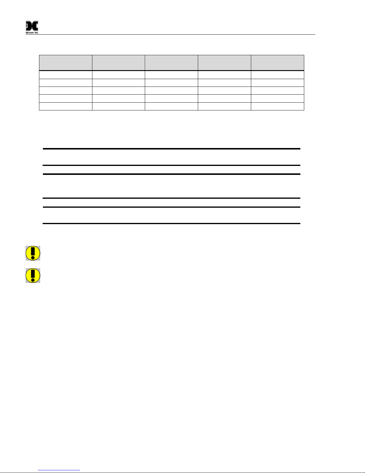
Table 1 Wire Gauge vs. Distance
AWG Wire Dia. Meters Feet
Over-Current
Protection
22
0.723mm
700
2080
3A
20
0.812mm
1120
3350
5A
18
1.024mm
1750
5250
7A
16
1.291mm
2800
8400
10A
14
1.628mm
4480
13,440
20A
Max loop load resistance between green and black wire is 500 ohms. Minimum loop load resistance between
green and black wire is 100 ohms. This is considers wire diameter, wire length, max operating temperature and
selected termination resistor.
NOTE 1: Wiring table is based on stranded tinned copper wire and is designed to serve as a
reference only.
NOTE 2: Shielded cable is required for installations where cable trays or conduit runs include
high voltage lines or other possible sources of induced interference. Separate conduit runs are
highly recommended in these cases.
NOTE 3: The supply of power should be from an isolated source with over-current protection
as stipulated in table.
Terminal Connections
CAUTION: Do not apply System power to the sensor until all wiring is properly terminated. Refer to
Section 2.7 Initial Start Up
CAUTION: Do not apply power to the sensor assembly in a hazardous area unless the junction box
cover is tight and all electrical seals have been installed
Model FP-700
FP-700 Instruction Manual Rev. 5.1 Page 13 of 46
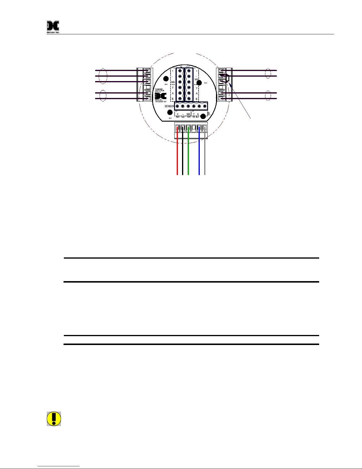
Customer
Supplied Wiring
(Out to next Device)
(+)
mA
(-)
A(+)
B(-)
Wiring to
Sensor Assembly
Wht
Blu
Red
Grn
Blk
Explosion
Proof
Junction Box
(+)
mA
(-)
A(+)
B(-)
(+)
mA
(-)
A(+)
B(-)
Customer
Supplied Wiring (In)
Modbus RS-485 to
Host Control Device
Power from and 4-20mA
out to Control Device
Install a 100-250 Ohm
resistor if the 4-20mA
output is not used
Modbus RS-485 to
next Device
Figure 14 Sensor Wire Connections
a) Remove the junction box cover. Identify the terminal blocks for customer wire connections.
b) Observing correct polarity, terminate the 3-conductor 4-20mA field wiring (+, -, mA) to the sensor assembly
wiring in accordance with the detail shown in Figure 14. If the 4-20mA output is not used, the green wire
from the sensor must be connected to the (-) terminal on the Transient Protection Module.
NOTE: If the 4-20mA output is not being used, the Green wire from the sensor must be
connected to the Black wire at the (-) terminal on the Transient Protection Module to
ensure proper sensor operation.
a) If applicable, terminate the RS-485 serial wiring as shown in Figure 14. Use the second plug (Out) as
termination point on the customer side to facilitate a continuous RS-485 serial loop
The RS-485 (if applicable) requires 24 gauge, two conductor, shielded, twisted pair cable between sensor and
host PC. General Cable Commodore part number ZO16P0022189 is recommended.
NOTE: Install a 120Ω resistor across A & B terminals on the last sensor in the serial loop.
c) Trim all exposed wire leads if they are not permanently landed in the terminal block.
d) Replace the junction box cover.
2.7 Initial Start Up
CAUTION: Do not apply power to the sensor assembly in a hazardous area unless the junction box
cover is tight and all electrical seals have been installed

Model FP-700
FP-700 Instruction Manual Rev. 5.1 Page 14 of 46
Upon completion of all mechanical mounting and termination of all field wiring, apply system power in the
range of 11.5-30VDC (24VDC typical) and observe the following normal conditions:
a) FP-700 display reads “0”, and no fault messages are flashing.
b) A temporary upscale reading may occur as the sensor heats up. This upscale reading will decrease to 0ppm
within 1-2 minutes of power-up, assuming there is no combustible gas in the area of the sensor.
NOTE: The 4-20mA signal is held constant at 4mA for the first two minutes after power up.
Initial Operational Tests
After a warm up period of 1 hour, the sensor should be checked to verify sensitivity to combustible gas.
Material Requirements
•Detcon PN 613-120000-700 700 Series Splash Guard with integral Cal Port –OR-
•Detcon PN 943-000006-132 Threaded Calibration Adapter
•Detcon PN 942-520124-050 Span Gas; 50% LEL methane/balance Air at fixed flow rate of 200-
500cc/min (use with 0-100% LEL range).
•Detcon PN 942-520124-025 Span Gas; 25% LEL methane/balance Air at fixed flow rate of 200-
500cc/min (use with 0-50% LEL range).
NOTE: Do not use calibration gases in Nitrogen background gas mixtures. This will cause
significant reading inaccuracies.
a) Attach the calibration adapter to the threaded sensor housing. Apply the test gas at a controlled flow rate of
200 – 500cc/min (200cc/min is the recommended flow). Allow 1-2 minutes for the reading to stabilize.
Observe that during the 1-2 minutes the ITM display increases to a level near that of the applied calibration
gas value.
NOTE: Check response time by confirming that the reading comes onto scale in first 5 seconds and reaches
approximately 50% of the applied gas within 10-15 seconds and reaches approximately 90% of the applied gas
in 30-40 seconds.
b) Remove test gas and observe that the ITM display decreases to “0”.
Initial operational tests are complete. Detcon FP-700 combustible gas sensors are factory calibrated prior to
shipment, andshould not require significant adjustment on start up. However, it is recommended thata complete
calibration test and adjustment be performed 16 to 24 hours after power-up. Refer to zero and span calibration
instructions in Section 3.4.Operation
Model FP-700
FP-700 Instruction Manual Rev. 5.1 Page 15 of 46
3. Operation
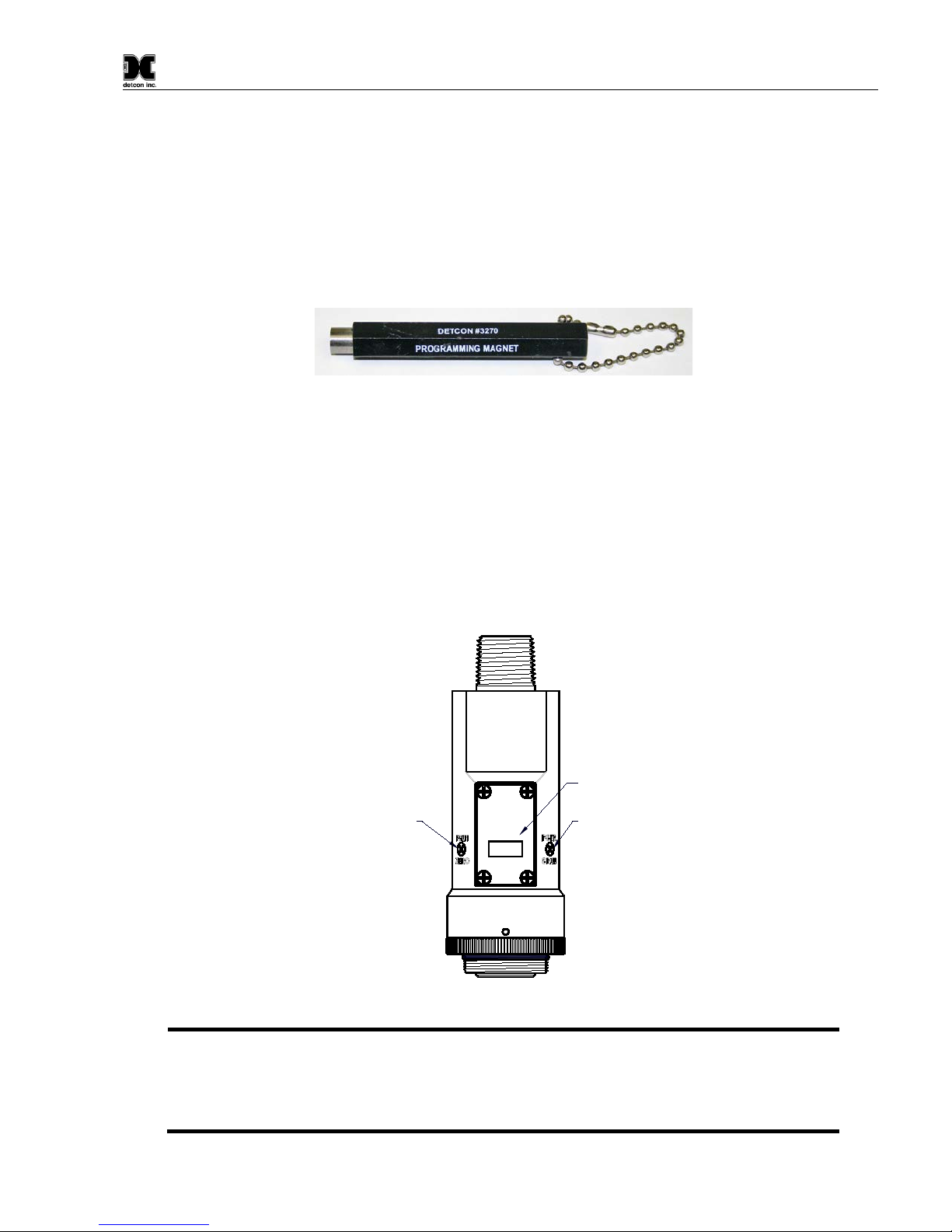
3.1 Programming Magnet Operating Instructions
The Operator Interface of the Model 700 Series gas sensors is accomplished via two internal magnetic switches
located to either side of the LED display (see Figure 16). The two switches, labeled “PGM1” and “PGM2”,
allow for complete calibration and configuration and thereby eliminate the need for area de-classification or the
use of hot permits.
Figure 15 Magnetic Programming Tool
The magnetic programming tool (Figure 15) is used to operate the magnetic switches. Switch action is defined
as momentary contact, 3-second hold, and 10-second hold. (Hold times are defined as the time from the point
when the arrow prompt “◄“appears.) For momentary contact use, the programming magnet is briefly held over
a switch location. For 3-second hold, the programming magnet is held in place over the switch location for three
seconds. For 10-second hold, the programming magnet is held in place over the switch location for 10 seconds.
The 3 and 10 second holds are generally used to enter calibration/program menus and save new data. The
momentary contact is generally used to move between menu items and to modify set-point values. Arrows (“◄”
and “►”) are used on the LED display to indicate when the magnetic switches are activated. The location of
“PGM1” and “PGM2” are shown in Figure 16.
Program Switch #1
LED Display
Program Switch #2
detcon inc.
LEL Sensor
MODEL
FP-700
Figure 16 Magnetic Programming Switches
NOTE: While in the Program Mode, if there isno magnetic switch interaction after 4 consecutive
menu scrolls, the sensor willautomatically revert to normal operating condition. While changing
values inside menu items, if there is no magnet activity after 3-4 seconds the sensor will
revert to the menu scroll.
(Exception to this is with “Signal Output Check” mode.)

Model FP-700
FP-700 Instruction Manual Rev. 5.1 Page 16 of 46
3.2 Operator Interface
The operating interface is menu-driven via the two magnetic program switches located under the target marks
of the sensor housing. The two switches are referred to as “PGM1” and “PGM2”. The menu list consists of
three major items that include sub-menus as indicated below. (Refer to the complete Software Flow Chart.)
Normal Operation
Current Reading and Fault Status
Calibration Mode
AutoZero
AutoSpan
Program Mode
View Sensor Status
Sensor Model Type
Current Software Version
Range of Detection
Serial ID address
AutoSpan Level
Days From Last AutoSpan
Remaining Sensor Life
Sensor Bridge Current
Sensor Bridge Voltage
Gas Factor
Cal Factor
4-20mA Output
Input Voltage Supply
Operating Temperature
Set AutoSpan Level
Set Gas Factor
Set Cal Factor
Set Serial ID
Set Bridge Voltage
Signal Output Check
Restore Default Settings
Table of contents
Other Detcon Accessories manuals

Detcon
Detcon PI-700 User manual

Detcon
Detcon FP-524D User manual

Detcon
Detcon DM-500IS OLED Series User manual

Detcon
Detcon MicroSafe DM-534C User manual

Detcon
Detcon CXT-DM User manual

Detcon
Detcon SmartWireless CX User manual

Detcon
Detcon DM-700 User manual

Detcon
Detcon MicroSafe TP-524C User manual

Detcon
Detcon TP-524D User manual

Detcon
Detcon IR-700 User manual


