digicon Turnstile Duo User manual

Product Manual
Turnstile
Duo

Turnstile
Duo

Copyright
All rights reserved. No part of this publication may be reproduced,
transmitted, transcribed, stored in a retrieval system, translated into any language
or computer language in any electronic, magnetic, optical, chemical, manual way,
or otherwise, without the express written permission from Digicon S.A.
Códe: 069.31.222
Version: 02 - English
Digicon S.A. Electronic Control for Mechanics – 2015
This manual was elaborated by:
Digicon S.A. Electronic Control for Mechanics Documentation Sector - EDS
Turnstile
Duo

1. Important instructions 05...........................................................................................
2. Orientations 06................................................................................................................
3. Introduction 06...............................................................................................................
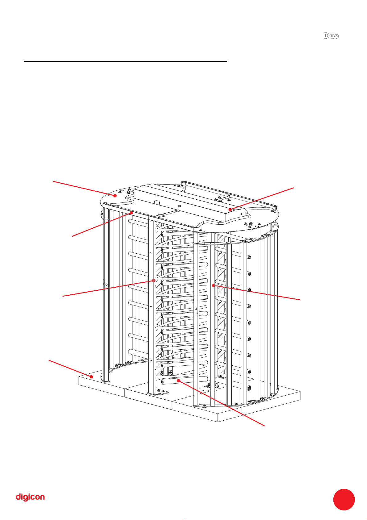
4. Features of Turnstile Duo 07.....................................................................................
5. Turnstile Duo operation 08.........................................................................................
6. Installing Duo 09............................................................................................................
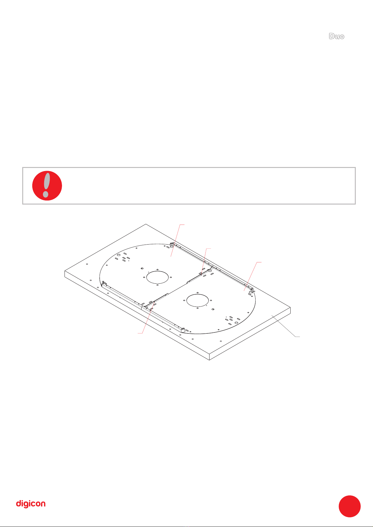
6.1 Preparing assembly of Duo 09...............................................................................
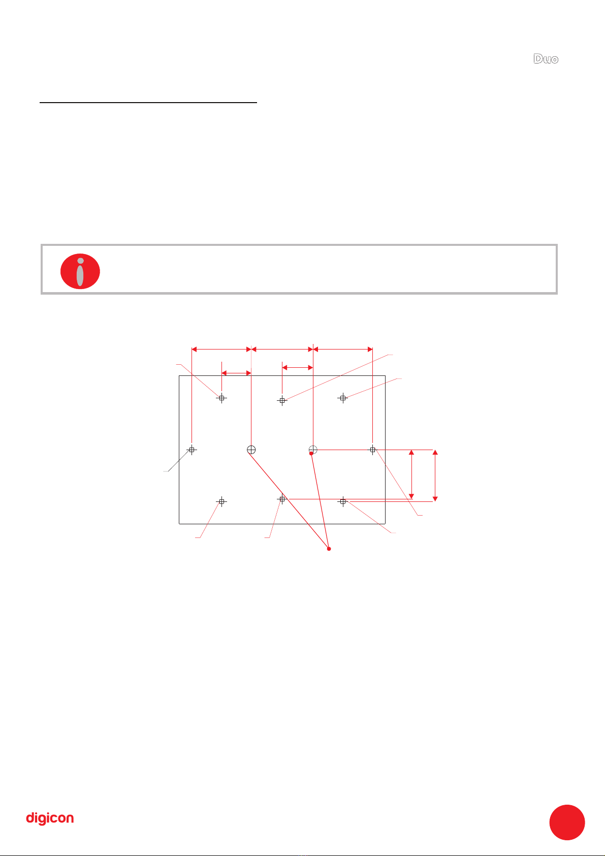
6.2 Drilling device 10.........................................................................................................
6.3 Lateral assembly with rods or glasses 11..........................................................
6.4 Assembling the arms 12...........................................................................................
6.5 Fixing bearing rods 14..............................................................................................
6.6 Fixing the sides 15......................................................................................................
6.7 Assembling stationery arms 16..............................................................................
6.8 Fixing stationery arm 17..........................................................................................
6.9 Fixing the roof 18........................................................................................................
6.10 Fixing the coverage 19...........................................................................................
6.11 Fitting the pivoting arm 20...................................................................................
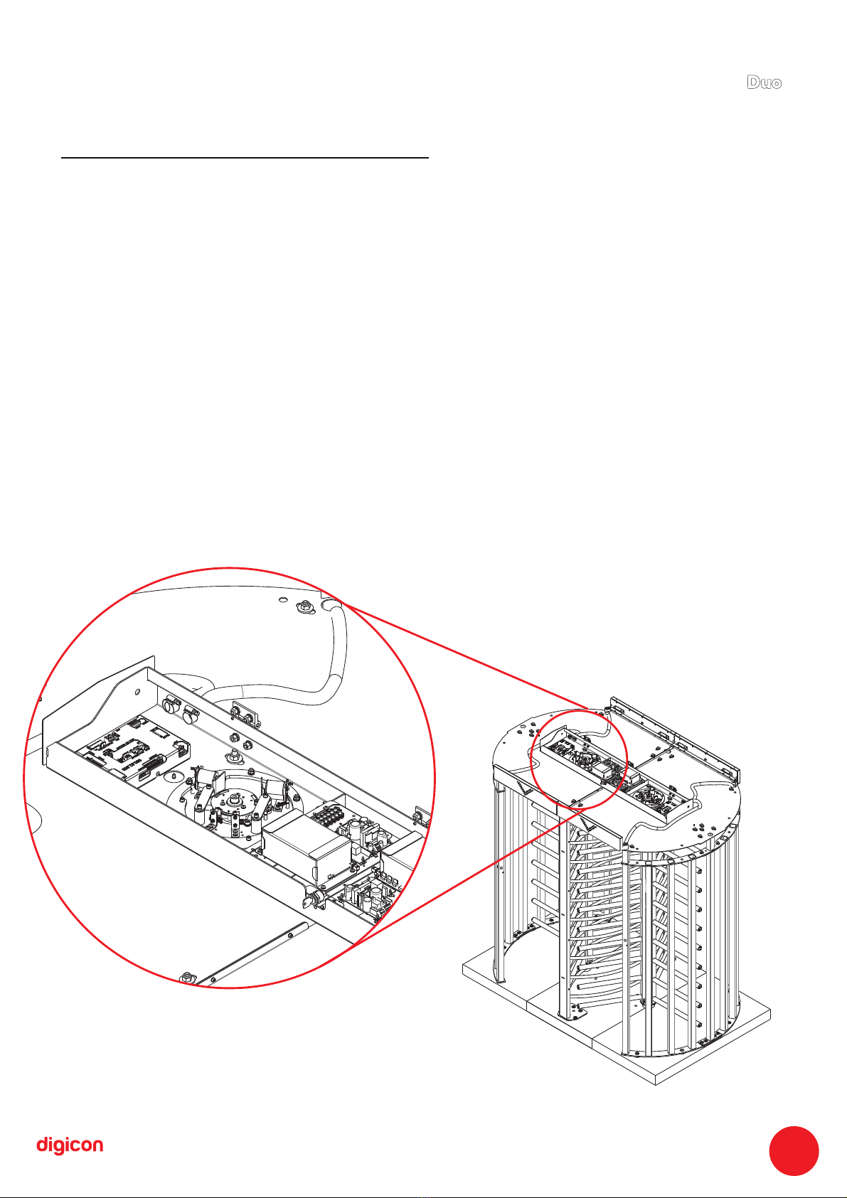
6.12 Fitting the lock system 21.....................................................................................
6.13 Cable passage 22.....................................................................................................
6.14 Mounting the card reader bracket 22................................................................
6.15 Turnstile assembled 23...........................................................................................
7. Optional items 23..........................................................................................................
7.1 Power supply 23...........................................................................................................
7.2 ontrol board 24C ..........................................................................................................
7.2.1 Inputs 26....................................................................................................................
7.2.2 Outputs 27.................................................................................................................
7.3 Configuration of control board – switch Ds1 29..............................................
7.4 Examples of configuration 29.................................................................................
7.5 serial communication 30...........................................................................................
7.6 Orientation pictogram kit 31..................................................................................
8. Module 31MCA ...............................................................................................................
8.1 Powering up Duo 32....................................................................................................
8.1.1 Initializing Duo 32.....................................................................................................
8.1.2 Configuring Digicon Firmware 32.....................................................................
9. Maintenance 35..............................................................................................................
9.1 Preventive and corrective maintenance routine 35........................................
9.2 defects, causes, and solutions 37.........................................................................
9.3 Dimensions 38..............................................................................................................
9.4 Other information 40.................................................................................................
10. Warranty and technical assistance 41.................................................................
Contents:
Turnstile
Duo

1. mportant nstructionsI i
You can see, below, the symbols that will appear in this manual,
signaling important moments. It is essential to pay attention to them.
TIP: Indicates something Digicon considers important.
CAUTION: Indicates a moment of extreme caution when
handling the equipment/product
ATTENTION: Indicates a moment when your observation
skills should be extremely productive.
INFORMATION: Presents interesting facts about the
purchased product.
QR CODE: Presents additional information or links
with more details about the presented text.
05
Turnstile
Duo

2. Orientations
Read the information and instructions of this manual carefully, before using the
product. This ensures the correct use of the equipment and maximum use of its
technical features as well as a prolonged service life.
Keep this manual for future consultations.
Digicon reserves its right to alter its products at any moment to adapt them to more
recent technical advancements.
Digicon maintains its right to alter the information contained in this manual without
previous notice.
Digicon does not provide any contractual warranty concerning the information in
this manual, and cannot be held responsible for errors it may contain and problems
due to its use.
The information contained in this manual is exclusive property of Digicon and is
protected by copyright laws.
This manual cannot be reproduced, photocopied or translated, in its entirety or in
part, into any kind of medium, without Digicon's written consent.
3. Introduction
The Full-height turnstile Duo is a bidirectional access control equipment for entrance
and exit of pedestrians. Highly resistant, both indoors and outdoors, it is sturdy, safe,
and firmly fixated to the floor. It is completely integrated to access controllers. This
manual presents a detailed description the installation of Duo and of the components
that accompany it.
To see our complete catalogue, visit www.digicon.com.br.
06
Turnstile
Duo

4. Features of Turnstile Duo
Bidirectional access control equipment for entrance and exit of pedestrians. The double
configuration optimizes the space and facilitates installation.
Highly resistant both indoors and outdoors
Robust, safe, and firmly fixed to the floor.
Complete integration to access controllers.
Two rotating axles with Digicon mechanism and control.
Treatment and finishing hat allow its installation outdoors.
Last arm rubberized with user protection against impact.
Internal lighting.
Gabinet/Coverage
Set of picot f
Roof
Base (floor)
Column
(stationery arm)
Orientation
pictogram (optional)
07
Rubberized arm
(protection against impact)
Turnstile
Duo

5. Turnstile Duo operation
In the basic mechanism, Turnstile Duo has bidirectional motorized turning with two 12 V
electromagnets for activating the locks and two optic sensors that can provide the signal
for activating the electromagnets and to the return of passage.
The electronic model includes a microprocessor control board (optional), where a signal
enabling passage is sent through one of the inputs, depending on the passage direction. If
this signal is recognized, the equipment will allow the turning of the arm of Duo. After half
of the turning is complete (60 degrees), a 400 milliseconds returning signal will be sent,
informing the passage direction. After the signal, the arm cannot be returned to the
previous position.
Depending on the Duo model and configuration, if the passage is forced without the
enabling signal, an electromagnet will be activated to prevent turn. In addition, the
equipment can emit a signal for a sound alarm and/or the exhibition of a red X on the upper
panel display (models with pictogram). In this case, a return signal will be sent, indicating
that the turnstile was forced, informing the direction of turn.
08
Turnstile
Duo

750 (29,527")
362
(14,252")
725 (28,543")
375
(14,763")
725
(28,543")
628
(24,724")
597
(23,503")
Ponto de referência
Centro de giro dos braços do Torniquete
P3
P1
P2 P4
P5
P6
P7
P8
6.Installing Duo
6.1 Prepare the Turnstile assembly
The floor where the turnstile will be fixed must meet the following specifications:
a. Dimensions: Direction of flow 2.4m x columns width 1.4m x concrete height 0.1 m;
b. Necessary height: 2.4 meters;
c. Level the floor for better product performance;
d. Floor specification ( 15 M.P.A. concrete or equivalent);FCK
e. Adequate area for assembling the turnstile: 2.4m x 1.4m x 2.6m.
Power point input and network cable can be on the floor, preferably at point 3 or overhead
pipes.
Obs.: The dimensions of the concrete block and power inputs are only a suggestion. The
client can choose smaller bases (footing) at the fixing points (determined by template).
List of tools for assembling the Turnstile:
1 socket wrench with socket of 14 and 17mm
1 combination wrench 17
1 socket wrench 10 with extension
1 n.3 Allen wrench
INFORMAÇÃO: milimeters andIllustrative image (measures specified in
inches.)
09
1 n. 5 Allen wrench
1 medium-sized Philips screwdriver
1 medium-sized screwdriver
1 hard plastic hammer
1 plum-line or water level
Turnstile
Duo

6.2 Drilling device
a. t will be necessary to add cardboard or bubble wrap under the device so not to damageI
the roof painting when using the drilling demarcations;
b. Screw the device (P1) to the turnstile's roof (P1);
c. osition the assembled parts in the area chosen for installation, observing the flow ofP
entrance and exit;
d. bserve the desired side for the opening (lock side) of the central support forO
maintenance;
e. lace the roof (P1) and fix tem with screw (P2) and nut (P3)P
f. he pre-hole must be done with an Ø6mm drill, so there are no damages to the device'sT
holes;
g. emove the device and drill again all the holes with an Ø14mm drill.R
Quantity of parts used in this stage:
P1 = 2x Roof
P2 = 2x Allen screw M4x12
P4 = 2x Nut M4
Obs.: After all demarcations, disassemble the device to use the part later (P1).
10
P1
P1
P2-P3
P2-P3 Piso
ATTENTION: The place of installation and the direction of entrance and exit
must be defined alongside the responsible for the place.
Turnstile
Duo

6.3 Assembly of sides with rods or glass sides
Sides with rods:
a. Fit the sides (P5) and (P6) so to form an arch;
b. Screw the sides using washer (P7) and screw (P8); repeat on the four fixing points
(two on the upper part, two on the lower part);
c. Place the screw (P26) with washers (P7) on both sides and on the nuts (P18) to finish
the holes on the arch's upper part.
Quantity of parts used in this stage:
P5 = 1x - 5 side rods
P6 = 1x- 4 side rods
P7 = 8x - Washer D=30,5 x 10,5 x 3mm
P8 = 4x – Hexagon head screw M10 x 20
P18 = 2x - Nut M10
P26 = 2x – Hexagon head screw M10 x 30
This assembly will result in the set (P23) – Assembling the arch's sides
P5
P18
P26
P8
P7
P6
11
INFORMATION: Make this assembly twice, since the turnstile is ouble.d
Turnstile
Duo

6.4 Assembling central arms
a. ix the inner triangle (P9) to one of the arms (P10) using the screw and the springF
washer (P11); repeat it for the arm's two fixing points (P10). Fixing this part is done
internally in the arms that have no buffer. Do not fasten the screw, simply position it.
b. Place the second arm (P10), fixing it to the inner triangle (P9) using the screw ad
the spring washer (P11). Repeat it for the arm's two fixing points (P10). Fixing this
part is done internally in the arms that have no buffer. Do not fasten the screw, simply
position it.
c. Place the third arm (P10), fixing it to the inner triangle (P9) using the screw ad the
spring washer (P11). Repeat it for the arm's two fixing points (P10). Fixing this part is
done internally in the arms that have no buffer. Do not fasten the screw, simply
position it.
d. Fit the lower base set (P14) to the lower part of the assembled arms (P10); place
the washers (P17) 2x, screw (P16) 1x, and nut (P18) 1x in each of the holes 3x. Do not
fasten the screw to the nut, only position it.
e. Fit the upper base set (P15) to the upper part of the assembled arms (P10); place
the washers (P17) 2x, screw (P16) 1x, and nut (P18) 1x in each of the holes 3x. Do not
fasten the screw to the nut, only position it.
P11
P11
P9
P10
12
INFORMATION:
The position of the tube without buffer can alter according to the turnstile
model.
Perform this assembly twice because the Turnstile is double.
Turnstile
Duo

P18
P16
P14
P17
f. Base set assembled. Do not fasten it.
P15
P17
P16
P18
g. t.Upper base set assembled. Do not fasten i
P9 = 2x - Triangle
P10 = 3x – Central arm
P11 = 6x - Allen screw M8 x 10
P14 = 1x – Lower base
P15 = 1x – Upper base
P16 = 6x – Hexagonal head screw M10 x 80
P17 = 12x - Washer D=22 x 10,5 x 3mm
P18 = 6x - Nut M10
13
Quantity of parts used in this stage:
Turnstile
Duo

6.5 Fixing the bearing support
a. ;Replace the fastener's washer (P21) for the washer (P7)
b. ;Use the fastener (21); does not accompany the product
c. Place silicone rubber under the bearing; then fix the bearing support (P19) to
the central hole, as shown in the image.
Quantity of parts used in this stage:
P7 = 1x - Washer D= 30,5 x 10,5 x 9mm
P19 = 1x – Bering
P21 = 1x - Fastener
ISOMETRIC VIEW
P19
UPPER VIEW
Screw must be
centralized in
the bearing. .
P7
P21
INFORMATION:
Add more Molykote grease to the bearing since the grease sent is for
transport only.
Repeat the operation above in the both rotating centers.
14
Turnstile
Duo

6.6 Fixing the sides
Fixing the sides with rods:
a. ;
Set the coincident flanges (P22) in the holes of the floor
b. Align the assembly of the sides with grid (P23) over the flanges, coinciding
with the holes;
c. ;
Replace the fastener's washer (P21) by the washer (P7)
d. ;
Place the fasteners (P21) in all fixing points
e. ;
Level the rod and wedge the base with washers, if correction is necessary
f. .
Fasten all the screws
Quantity of parts used in this stage:
P7 = 6x - Washer D=30,5 x 10,5 x 3mm
P21 = 6x - Fastener
P22 = 6x - Flange
P23 = 1x (Assembly obtained in step 3) -
Assembly of arch's sides
P23
P7
P21
P22
P7
P21
15
INFORMATION: Perform this assembly wice because the turnstile is
double.
Turnstile
Duo

P49
P50
P51
P52
P52
P53
P53
P49
P51
P53
6.7 Fixing the stationery arms
a. Poisition the arches (P50) and (P51) with the support (P49)
b. Fix tem using the screws (P53), aligning the faces of the arches (P50) and
(P51)
c. Fasten all the screws (P53)
d. Position the stationery arms (P52) on both sides
e. Fasten the screws in place (P53)
Quantity of parts used in this stage:
P49 = 8x - Support
P50 = 1x - Arch 1
P51 = 1x - Arch 2
P52 = 2x – Stationery arm
P53 = 32x - Screw M5x20
16
Turnstile
Duo

6.8 Fixing the stationery arm
a. Set the stationery arm (P24) over the flanges and coinciding holes;
b. Replace the fastener's washer (P21) by the washer (P7);
c. Place the fasteners (P21) in all fixing points;
d. Fasten all the screws;
e. Level the column and wedge it with washers, if necessary;
f. Check if the arms are perpendicular to the floor's point of reference.
Quantity of parts used in this stage:
P7 = 4x - Washer D=30,5 x 10,5 x 3mm
P21 = 4x - fastener
P22 = 4x - Flange
P24 = 1x – Stationery arm
17
P24
P07
P21
Turnstile
Duo

6.9 Fixing the roof
a. Place the roofs (P1) over the sides (P23 or P48);
b. Screw them in place, using in each fixation 2 washers (P7), screw (P26), and nut (P18).
Place the screw from the bottom upwards.
c. Screw the roofs between themselves using 2 washers (P54) to fix them, screw (P55), and
nut (P56).
Quantity of parts used in this stage:
P1 = 1x - Roof
P7 = 4x - Washer D=30,5 x 10,5 x 3mm
P18 = 2x - nut M10
P26 = 2x – Hexagonal head screw M10 x 30
18
P01
P01
P23 ou P48
P23ou P48
P07 P18 P26
P07P18P26
P07P18P26
P54P55P56
P54 P55 P56
P54 P55 P56
P07P18P26
P23 = Side assemble with rods
P48 = Side assemble for glass
P54 = 12x – washer M4
P55 = 6x Allen screw M4x12
P56 = 6x nut M4
Turnstile
Duo

P01
P27 P07 P18P26
P07P18P26
P07P18P26
6.10 Fixing the coverage
a. Check the height from the floor to the upper part of the roof (P1) – 2.1 meters with
tolerance of 5mm;
b. Place the turnstile coverage (P27) over the roof (P1) and the stationery arm (P24);
c. In each fixation, use 2 washers (P7), screw (P26), and nut (P18). Obs.: place the
screw from the bottom upwards. Do not fasten it.
d. After aligning, fasten the screws in all the fixing points of the turnstile coverage
(P27).
Quantity of parts used in this stage:
P7 = 16x - Washer D = 30,5 x 10,5 x 3mm
P18 = 8x - Nut M10
P26 = 8x – Hexagonal head screw M10 x 30
P27 = 1x - Coverage
19
Turnstile
Duo

6.11 Fitting of central pivoting arm
a. ;Grease the bearing support (P19). (We recommend Molykote -2 Plus greaseBR
b. Fit the central arms assembly (P28) in the bearing support (P19). In this stage,
the assembler or mechanic cannot drop the central arms assembly, so we suggest an
auxiliary assembler or to tie the central arm to the structure;
c. Align one of the line of arms to the stationery arms, as shown in the image.
Quantity of parts used in this stage:
P28 = 2 sets (Assembly obtained in the 4 step of this Manual) – Central
th
arm
20
P28
P28
P28
P19
P28
P19
Turnstile
Duo
Table of contents
Other digicon Turnstile manuals