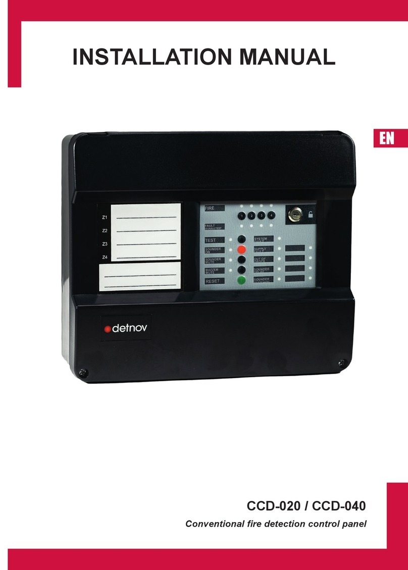
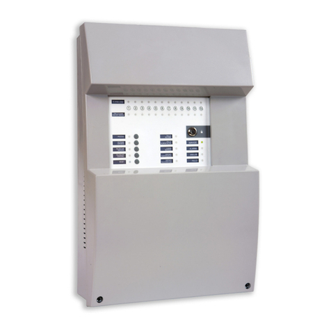
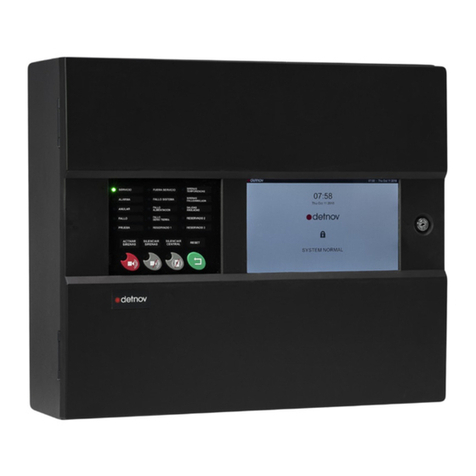
Detnov CAD-250 User manual

ENG
INSTALLATION
GUIDE
ENG

ENG
2

3
ENG

ENG
4
Revision control
Revision Comment Date
a First edition 29/11/2019
b Typographical errors and regulatory references 05/12/2019
c 16/12/2019
d Lay out remake and revision 16/06/2020

5
ENG
Conditions of use
Before installing the CAD-250 control panel, you must check that a series of criteria are met.
If these criteria are not met, the control panel may be damaged, problems may arise during system start-up or the functioning of the system may be

ENG
6
CONTENTS 1. INTRODUCTION ..........................................................................8
1.1. ABOUT THIS MANUAL...........................................................8
1.3. DISCLAIMER ..........................................................................8
1.3. STANDARDS AND COMPLIANCE.........................................5
1.4. ADDITIONAL INDICATIONS...................................................9
1.5.GENERAL SAFETY WARNINGS ............................................9
1.6. REQUIRED DOCUMENTATION AND DESIGN......................10
1.7. EXPLICIT DEFINITIONS ........................................................10
1.8. MAIN FEATURES OF THE CONTROL PANEL ......................11
1.9. ARCHITECTURE ....................................................................11
1.10. INSPECTION ..........................................................................14
1.11. REQUIREMENTS ...................................................................15
1.11.1. Assembly notes..........................................................................15
1.11.2. Installation notes ........................................................................15
..................................................................15
2. ASSEMBLY GUIDE ......................................................................16
2.1. CABLE ENTRIES....................................................................16
2.2. ATTACHMENT ........................................................................18
3. CONNECTION GUIDE .................................................................20
3.1. INTERNAL PARTS..................................................................20
3.2. INSERTABLE LANGUAGE CARD..........................................22
3.3. MAIN BOARD PROTECTION.................................................23
3.4. MAIN BOARD .........................................................................24
3.5. CONNECTING TO THE MAINS .............................................26
3.6. CONNECTING THE BATTERIES...........................................27
3.7. LOOP CARDS ........................................................................28
3.8. ADDRESSABLE LOOPS ........................................................30
3.8.1 Loop continuity..............................................................................31
3.8.2 Connecting devices ......................................................................31
3.8.3 Addressable loop ..........................................................................32
3.8.4 Loop check ...................................................................................33

7
ENG
6. MAINTENANCE ...........................................................................58
6.1. LOG ........................................................................................58
6.2. PERIODIC TESTS ..................................................................58
6.2.1. Test Mode ....................................................................................58
6.3. CLEANING..............................................................................59
7. TROUBLESHOOTING .................................................................60
7.1. PRIMARY CONTROLS...........................................................60
7.2. EVENTS SCREEN..................................................................62
8. TECHNICAL SPECIFICATIONS ..................................................66
ANNEX 1: TOTEM INSTALLATION.................................................68
ANNEX 2: COMPATIBLE DEVICES and CONSUMPTION.............76
ANNEX 3: AUTONOMY AND LOOP CALCULATION.....................79
3.9. SOUNDER OUTPUT ..............................................................34
3.9.1. Cancelling sounder outputs ......................................................... 34
3.9.2. Checking the sounder line ........................................................... 34
3.9.3. Polarised sounder connection .....................................................35
3.9.4. NON-polarised sounder connection.............................................35
3.10. 24 V AUXILIARY OUTPUT ...................................................36
3.11. CONNECTING TO THE FAULT RELAY................................36
3.12 CONNECTING TO THE ALARM RELAY ..............................36
3.13. FINAL CONNECTION CHECKS...........................................37
3.14. COMMUNICATIONS CARD (OPTIONAL)............................37
4. START-UP ....................................................................................42
4.1. MAIN PANEL...........................................................................42
4.2. GENERAL LEDS.....................................................................42
4.3. PRIMARY CONTROLS...........................................................43
4.4. INITIAL START-UP..................................................................43
5. QUICK CONTROL PANEL CONFIGURATION............................44
5.1. ADMINISTRATOR ACCESS ...................................................44
5.2. ADMINISTRATOR SCREEN...................................................45
5.3. CONFIGURATION ..................................................................46
5.3.1. Control panel description.............................................................46
5.3.2. Contact phone .............................................................................46
5.3.3. Installer information .....................................................................46
5.3.4. Date selection..............................................................................46
5.4. LOOP AUTOSEARCH ............................................................47
5.5. DEVICES ................................................................................48
...............................49
5.6. SECTORISATION...................................................................50
5.7. MANOEUVRES ......................................................................52
5.8. SOFTWARE UPDATE ............................................................55
5.9. PANEL TEST...........................................................................56
5.10. ETHERNET PORT CONFIGURATION.................................57

ENG
8
1. INTRODUCTION
1.1. ABOUT THIS MANUAL
descriptions regarding procedures and technical details necessary to
control panels.
For each step in the assembly, connection and start-up process of
instructions to be understood.
The accuracy of the contents of this manual is the most important
notice.
1.2. DISCLAIMER
accept any responsibility for any misinterpretation of an instruction or
guidance note or for full system compliance.
control panel manufacturer.
1.3. STANDARDS AND COMPLIANCE
The distinctive CE on this control panel indicates
regulations of the European Community.
Directive Standard Description
2014/30/EU Electromagnetic Compatibility Directive
2014/35/EU
305/2011/EU Construction Products Directive
EN54-2
EN54-4
STORE THIS MANUAL. It contains important
instructions regarding installation and use. It is
possible that you may need to consult it in the future.
KEEP THE BOX. It contains a printed template to
facilitate assembly. You may need the packaging to
send the control panel to the technical service or to
move the unit to another location.

9
ENG
1.4. ADDITIONAL INDICATIONS
2011/65/EU (RoHS 2), European standard on the
restriction of the use of certain harmful substances
polybrominated biphenyls, polybrominated diphenyl
ethers) in small and large household appliances,
electrical and electronic tools, toys, leisure and sports
instruments, including industrial control instruments,
in the previous categories.
2012/19/EU (WEEE), European standard on the
recycling of non-disposable products, such as
dispose of it at the collection points designated for this
purpose in order to facilitate its appropriate recycling.
1.5. GENERAL SAFETY WARNINGS
ONLY STAFF THAT ARE DULY QUALIFIED MUST INSTALL
OR CONFIGURE THIS UNIT.
Read this manual carefully before beginning to install the
panel.
MAKE SURE you have the appropriate tools
damage to the unit, the facility to malfunction or safety risks
for people.
normal distributor or customer service before continuing to
install the unit.
applicable standards issued by the competent authority of the
corresponding country. Consult local, national and business
standards
Do not use the panel or its components beyond their
of -5°C to 40°C
earth.
The installation of the system on CAD-250 control panels must
include a method to isolate or disconnect the input voltage
supply. The isolation or disconnection device must be located
close to the system and be clearly labelled. The isolation or
disconnection device must disconnect both the active and the
Consider the incorporation of protection for the inputs against
overvoltages, depending on the type of location and risk
All signal and interconnection cables must be armoured and
this manual.
All ducts and the cable protection must be connected to the
the cable shield.
the system is connected in normal operation.
EN
UNE
ISO

ENG
10
1.7. EXPLICIT DEFINITIONS
installation may result in incorrect assembly or even death.
elements of the control panel that are sensitive to static current or short
circuits if the procedures, recommendations, regulatory references or
advice for facilitating the assembly, connection or installation processes
Word Denition
⚠WARNING! Risk of personal injury
Risk for the product and system
EN
UNE
ISO
Check according to the applicable regulations
There is no risk and no observations or comments to
facilitate the action
Go to the technical support service
Recommended action
Action not recommended or incorrect
1.6. REQUIRED DOCUMENTATION AND DESIGN
For the correct and complete installation, start-up, installation and
Document Description
MC 383 en 2020
CAD-250 control panel
MU 379 en 2020 CAD-250 control panel User Manual
MS 419 en 2020
Check that the manual version corresponds to the unit you are going
to install.
Detnov pays special attention to the compatibility of the components
described in this manual refer to the date of this document (on the
The most up-to-date information and the approvals for this are available
This guide does not describe the advanced features related to the
other manuals.

11
ENG
1.8. MAIN FEATURES OF THE CONTROL PANEL
The CAD-250
DETNOV
addressable sensors, modules and addressable butto. Its modular
Basic conguration (single panel):
10” TFT COLOUR SCREEN
USER-FRIENDLY MULTILINGUAL INTERFACE. The graphical
such as alarms or events.
2sounder outputs.
1 alarm output.
1fault output.
8 loops and 2000 devices (250 per loop).
1Ethernet connection.
1
64
1 GHZ PROCESSOR, high-speed microprocessor core.
512 MB RAM
8 GB FLASH
image databases, etc.
1.000.000 events in the history log.
1.9. ARCHITECTURE
modular components to be combined in a single structure of up to 4
sections or cabinets.
32 loops
8000 devices
2000 programmable zones
250 areas
1000 groups
250 virtual controls or relays
2500 special modes
Item Ref. Description
ACAD-250
The ref. does not include the
loops
BCAD-250-BLED
for zones
The ref. does not include the
loops
CCAD-250B
The ref. does not include the
loops
B
C
A

ENG
12
System composition
1 x CAD-250 +
1 x CAD-250LBLED +
2 x CAD-250 B
1 x CAD-250 +
1 x CAD-250LBLED +
1 x CAD-250 B
1 x CAD-250 +
1 x CAD-250LBLED
1 x CAD-250
• 2 monitored sounder outputs
• 2 voltage-free relay outputs on the board
•
• Capacity for the installation of 4 cards of 2 loops ref. TBUD-250
•
• Space for BTB-1224 batteries
OPTIONS
•
•
set

13
ENG
Network system composition
Up to 64 nodes
Up to 64 nodes

ENG
14
1.10. INSPECTION
Ref. Units Description Contents
CAD-250 1Addressable control panel
1Accessories bag
2Keys
11234720 2End-of-line sounder
monitoring element.
24001501 1
1
24001001 1
39310018 1Battery cable
55325001 1Insertable language kit
55325000 1Quick guide manual
39310020 1Battery jumper cable
If the control panel is damaged or any of these elements are missing,
1.10.1. Damage to the unit
1.
2. If the fault comes from the internal
boards.
3.
of reception of the product, photos of
the damage or fault, conditions of the
package, etc.
4. Send the data to your supplier.
5. If necessary, send the product to your
supplier using the original packaging.
STEP 5
Request return
with all information
STEP 1
Identify BATCH
STEP 2
Identify PCBs
STEP 3
Order data
Fault type
Capture photo
Package condition
STEP 4
Send information to supplier

15
ENG
A loop cable transmits data, so choosing the right cable is important.
•
recommended).
•
circulate through ducts that are separated from other circuits to prevent
problems of interference.
•
points described for the mesh.
• The mesh must have continuity throughout the loop ring path.
• Although for a standard facility the cross section of the loop cable is
facility.
•
normally red.
•
•
using cable glands.
EN
UNE
ISO
1.11. REQUIREMENTS
1.11.1. Assembly notes
KNOWLEDGE: Make sure you have the necessary mechanical and
TOOLS:
• An electric drill.
•
•
• Insulating tape.
• Measuring tape.
• Cutter.
•
•
1.11.2. Installation notes
Once the control panel is assembled and connected to the mains
Prevent electrical/electromagnetic and mechanical interferences, such
1.11.3. Detection loop wiring
UNE 23007-14
EN
UNE
ISO

ENG
16
2. ASSEMBLY GUIDE
or unnecessary actions.
2.1. CABLE ENTRIES
The CAD-250 has various cable entries. The entry covers can be
removed easily using pliers.
1 ENTRIES FOR CABLE GLANDS
the cables come through tubes or in a hose.
2 REAR CABLE ENTRY
3 SIDE CABLE ENTRY
right and left sides. These entries are practical if you are using a
conduit to guide the cables.
4 CABLE ENTRY FOR ASSEMBLING VARIOUS SECTIONS
maximum of 4 cabinets can be installed,
see section 1.9.).
5 ADDITIONAL REAR INPUT
6 LOWER INPUT
7 CABLE ENTRY FOR THE MAIN POWER SUPPLY
To do this, use the cable entry on the right to insert the cable to
AC connector.
L1 out L3
and 4
L1 in
L2 out
L2 in
L5 and 6 L7 and 8 RAlarm
RFault SND1
SND2
RS485
RJ45
RJ45
230 Vac
230 Vac

17
ENG
1
363
2
4 5

ENG
18
out this task.
1.
2.
insulating tape so that your hands are free.
3. Using the appropriate drill bit (for holes of 6 mm, use drill bit no. 12), drill the 4 holes.
4.
Take into account any cable or installation that can pass over, under or behind the unit.
5.NOT use countersunk
2.2. ATTACHMENT
STEP 1
Remove template
STEP 2
Place template,
check level
STEP 3
Drill holes in the wall
STEP 4
Fit the wall plugs
STEP 5
Attach the control
panel
step 1

19
ENG
1.5 metres
step 3
PHILLIPS/POZIDRIVE ROUND HEAD
PLUGS
DNP8 (8 mm)
452 mm
398 mm
step 4
step 2

ENG
20
5 MAIN BOARD
The MAIN BOARD contains the main processor, CPU, fuses,
or it could cause irreversible damage to the unit.
6 BATTERY CONNECTOR
When you connect the battery cable terminal, make sure this
could damage the main board.
7 POCKET FOR THE INSERTABLE LANGUAGE CARD
once you have inserted the card, the legends that accompany the
LEDs and control keys and primary LEDs (see sections 3.2 and 4.2).
3. CONNECTION GUIDE
3.1. INTERNAL PARTS
Before making any type of connection, identify the internal parts of the
are in order to access the interior of the control panel.
1 AC AND FUSE MAIN CONNECTOR
This is the main current input to the control panel. The main input
2 MAIN BOARD PROTECTION
installation.
3 POWER SUPPLY
is important that its air circulation is not impeded. Do not place the
4 ADDITIONAL CARD SUPPORT
Other manuals for CAD-250
2
Table of contents
Other Detnov Control Panel manuals
Popular Control Panel manuals by other brands

LSIS
LSIS iXP2H Series user manual

GARDINER TECHNOLOGY
GARDINER TECHNOLOGY Gardtec 800 installation instructions

DSC
DSC PC3OOO installation manual

Adveco
Adveco EB0025 product manual
Panasonic
Panasonic AWRP301 - PAN/TILT CONTROL PAN operating instructions
DMP Electronics
DMP Electronics XR150 series installation guide

TFS
TFS AdvantageLi Installation, operation and maintenance manual
EcoFlow
EcoFlow PowerInsight manual

Hydor
Hydor Bespoke Installation and maintenance instructions
Mircom
Mircom FA-1025T Installation and operation manual
Nortek Control
Nortek Control 2GIG GC2e installation guide

Skutt
Skutt EasyView w/LinkBoard Service training manual

