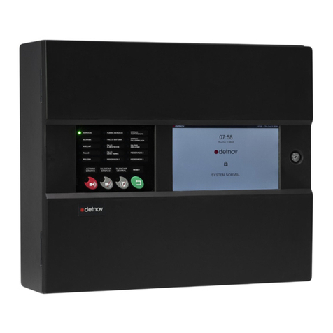
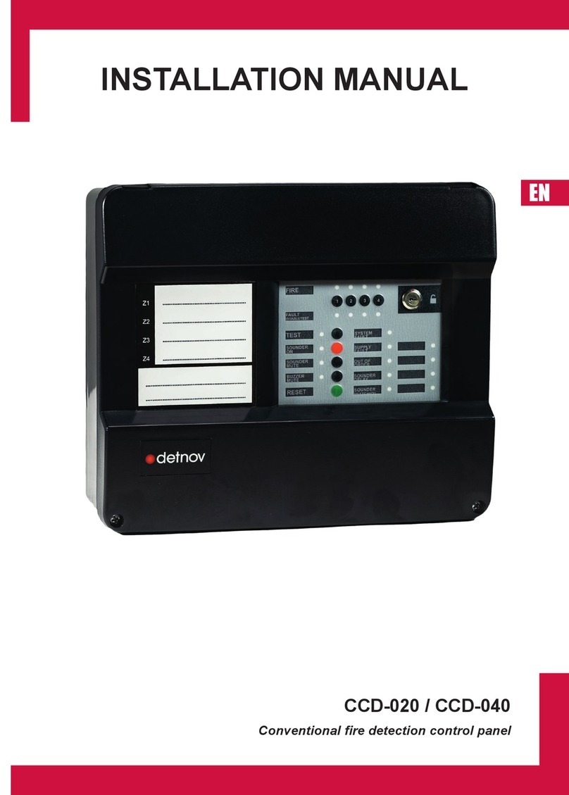
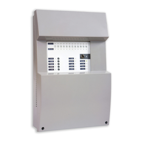
Detnov CAD-250 User manual

ENG
CONFIGURATION
GUIDE
ENG

ENG
2

3
ENG

ENG
4
Revision control
Revision Comment Date
a First edition. Software version 0.19.12 (27 Nov 2019) 09/04/2020
bUpdated layout. Software version 1.1.1. 16/06/2020

5
ENG
Before installing the CAD-250 control panel, you must check that a series of criteria are met.
If these criteria are not met, the control panel may be damaged, problems may arise during system start-up or the functioning of the system may be
lead to the warranty being voided.
Conditions of use

ENG
6
CONTENTS
1. INTRODUCTION............................................................................8
1.1.Disclaimer.................................................................................8
1.2.Standards and compliance .......................................................8
1.3. ..........................................................8
1.4.................................................................................8
1.5.About this manual.....................................................................9
1.6.Before getting started .............................................................10
1.7.Areas and zones.....................................................................11
2. VESTA SYSTEM ARCHITECTURE.............................................12
2.1.Loops and devices ................................................................12
2.2. .........................................................12
2.3.Alarm and control or manoeuvre outputs ...............................12
2.4.Panel ......................................................................................13
2.5.Nodes.....................................................................................13
3. INITIAL CONFIGURATION..........................................................14
3.1.User level................................................................................16
3.2...................................................................17
3.3.Main characteristics of the control panel ................................18
3.4.Main panel ..............................................................................18
3.5.General LEDs .........................................................................19
3.6.Primary controls......................................................................19
4. CONTROL PANEL CONFIGURATION .......................................20
4.1.Administrator access..............................................................20
4.2.Administrator screen ..............................................................21

7
ENG
7.4. ..................................................54
7.4.1.Description............................................................................................54
7.4.2.........................................54
7.4.3.Mode change in the sectorisation menu...............................................55
7.4.4.Test mode.............................................................................................55
7.4.5.Disabled mode......................................................................................55
8. MANOEUVRES ...........................................................................58
8.1.Main manoeuvres menu.........................................................59
8.2........................................................60
8.2.1.Inputs for manoeuvres, events. ......................................................61
8.2.2. ................................................................63
8.2.3.Outputs for the manoeuvres ...........................................................64
8.3.Group programming ...............................................................67
8.4.Virtual mode programming.....................................................70
8.5.Virtual module status..............................................................73
9. LOGS ...........................................................................................74
10. NETWORK .................................................................................78
10.1. ..........................................................78
10.2. ......................................................................80
11. FACILITY.....................................................................................82
11.1.Special modes......................................................................82
11.2. Two-step delay ....................................................................87
...............................................89
..................................................91
APPENDIX 1 ....................................................................................94
5. SETTINGS ...................................................................................22
5.1.General ..................................................................................22
5.1.1.Control panel description......................................................................22
5.1.2.Contact phone ......................................................................................23
5.1.3.Installer information ..............................................................................23
5.1.4.Language..............................................................................................23
5.1.5.Date selection.......................................................................................24
5.1.6.Screen settings.....................................................................................25
5.2.Versions .................................................................................26
5.2.1........................................................................................27
5.2.2.Installation from the USB port...............................................................28
5.3.Users......................................................................................30
5.4.Advanced ...............................................................................31
5.5.Connectivity............................................................................33
5.6.Printer.....................................................................................34
5.6.1.Printer options ......................................................................................34
5.6.2. ..................................................................34
5.7.Logs (event log) .....................................................................35
5.8.Test (display test) ...................................................................36
6. LOOP MENU................................................................................38
6.1.Devices ..................................................................................38
6.1.1. ....................................................40
6.2.Addressable value..................................................................42
6.3.Outputs...................................................................................44
6.4.Autosearch .............................................................................45
6.5.Autocheck ..............................................................................47
6.6............................................................48
6.7.Address programming............................................................49
7. SECTORISATION .......................................................................50
7.1 Sectorisation hierarchy and legacy mode ..............................50
7.2.Display controls......................................................................52
7.3.Filters .....................................................................................53

ENG
8
1. INTRODUCTION
1.1. DISCLAIMER
accept any responsibility for any misinterpretation of an instruction or
guidance note or for full system compliance.
The manufacturer's policy is of continuous improvement and we reserve
and without prior notice.
unit or the state of the detection wiring are not the responsibility of the
control panel manufacturer.
1.2. STANDARDS AND COMPLIANCE
The CE marking on this control panel indicates its compliance with
Directive Standard Description
2014/30/EU Electromagnetic Compatibility Directive
2014/35/EU Low Voltage Directive
305/2011/EU Construction Products Directive
EN54-2
EN54-4
1.3. REQUIRED DOCUMENTATION AND DESIGN
For the correct and complete installation, start-up, installation and
reference:
Document Description
MI 375 en 2020 CAD-250 control panel Installation Manual
MU 379 en 2020 CAD-250 control panel User Manual
MS 419 en 2020
Check that the manual version corresponds to the unit you are going
to install.
Detnov pays special attention to the compatibility of the components
compatibility notes between versions to ensure the greatest reliability
described in this manual refer to the date of this document and may
regulations and standards.
The most up-to-date information and the approvals for this are available
on our website www.DETNOV.com.
1.4. EXPLICIT DEFINITIONS
The procedures described in this manual include warnings and cautions
to advise the user to adopt methodical and safe working practices
Please heed the warnings in this manual, as incorrect use or improper

9
ENG
These warnings alert you to serious risks or precautions to consider
regulatory references or advice for facilitating the assembly, connection
or installation processes are not followed.
Word Denition
⚠WARNING! Risk of personal injury
Risk for the product and system
EN
UNE
ISO
Check according to the applicable regulations
There is no risk and no observations or comments
to facilitate the action
Go to the technical support service
Recommended action
Action not recommended or incorrect
1.5. ABOUT THIS MANUAL
minimum understanding of the system menus, with all kinds of
descriptions regarding procedures and technical details necessary for
and alarm system.
For each step in the process, a detailed description is included with
drawings, diagrams and charts, making these instructions easier to
understand.
The accuracy of the contents of this manual is the most important
manufacturer reserves the right to change the information without prior
notice.
The advanced graphical interface of the CAD-250 control panel allows
used by the start-up engineer.

ENG
10
1.6. BEFORE GETTING STARTED
must be organised and grouped so that both the detection of a potential
The speed of the response and with which action is taken is essential
for safeguarding people and minimising damage to the facilities.

11
ENG
1.7. AREAS AND ZONES
The subdivision of the space protected by the system is organised into what we call zones. These zones are subdivisions, whereby one protection function
is carried out independently of any other.
by the applicable regulation.
There may be limitations in terms of the size of the zones.
Areas. For the CAD-250 system, the zones are spatial subdivisions
restricted locally by a single panel, whereas the areas can break this restriction and constitute subdivisions on the control panel network level.
EN
UNE
ISO

ENG
12
2. VESTA SYSTEM ARCHITECTURE
VESTA
on CAD-250 control panels. This is an addressable control panel with
DETNOV addressable sensors, modules and addressable manual call
2.1. LOOPS AND DEVICES
The automatic detection elements, manual detection elements, manual
call points, monitoring modules or output elements, such as sounders
or control modules, are the devices that are connected to the CAD-250
control panels in a closed loop.
The control panel allows open loop operation, but the use of this
topology, whereby a single incident in the transmission lines can lead
Please note that some devices use more than one address. Go to
APPENDIX 1 at the end of the chapter to check the types of device
available, the number of addresses they use in the loop and their
consumption.
2.2. FIRE AND AUXILIARY INPUTS
The panel features automatic detectors, alarm manual call points and
The purpose of certain monitoring modules is to monitor signals that
modules. It must be indicated on the control panel when a module is
2.3. ALARM AND CONTROL OR MANOEUVRE OUTPUTS
If a hazard is detected or a control signal is received, the system
will carry out preset actions, either by default or the programming of
conditioned manoeuvres.
they are sounders or control modules.
associating manoeuvres, states and events, allowing the creation of
the most demanding emergency plans.

13
ENG
CONTROLLER
NORMAL NORMAL
NORMAL NORMAL NORMAL
NORMAL
NORMAL
2.4. PANEL
The modular design of the CAD-250 control panel allows up to 3
modular components to be combined in a single structure of up to 4
sections or cabinets.
versatility and power. As such, nodes or single control panels can be
generated with a capacity of:
32 loops per node
8000 devices per node
2000 programmable zones
250 areas
1000 groups
250 virtual controls or relays
2500 special modes per control panel
The panel typology to be used and the basic data of the facility must
2.5. NODES
The VESTA system allows a network architecture of up to 64 control
SCD-250
graphical interface, but it is more complicated to do it in that way. In the
1 x CAD-250 +
1 x CAD-250LBLED +
2 x CAD-250 B
Item Ref. Description
A CAD-250 Main cabinet with interface
The ref. does not include
the loops
B CAD-250-BLED Cabinet with 250 dual
LEDs for zones
The ref. does not include
the loops
C CAD-250B
The ref. does not include
the loops
Up to 64 nodes
A
B
C

ENG
14
3. INITIAL CONFIGURATION
Before you do anything else, a series of basic steps must be carried
out.
1.-
ing to the project.
2. -
gency plan.
3.
when carrying out manoeuvres, delay manoeuvres, actions conditioned
by times or dates, coincidences and automatic or monitoring actions.
4. -
mation manoeuvres.
5. Design a scenario plan for the actions, so that once the manoeuvres
have been carried out, you can check their compliance.
6.
7.
assigned to each panel. Although the system supports a random num-
bering of nodes, it is good practice to number the nodes consecutively.
8. Make sure you have assigned addresses to all devices in the system.
9.
assignment of addresses, though it is not recommended for the identi-
10. Check that no overlaps have been generated, remember that some
devices use more than one address, see APPENDIX 1 of this manual.
11. In general, this manual has been designed according to the menu
structure of the control panel interface for easy location of the menus,
apart from the initial settings menu, which is located at the start.
12. The system has 4 access levels.
Access level 1
• The events view
Control functions, such as:
• Control panel acoustic silencer
• Sounder silencer
• Sounder activation
• Reset
• Latched button functions.
•
For more information, see also the User Manual.
Access level 2 or user access provides access to:
• Entity disablement
•
• System settings menu review, including general data such as the
contact phone, installation company or language.
• Date setting
• Version review
• Printer setting
• Performing the LED and indicator test
For more information, see the User Manual.
Access level 3
Access level 4 -
-
ware manuals for PC.

15
ENG
Conguration steps
With the systems already installed, it may be necessary to edit a loop
unit due to updates or changes made in the facilities.
For the loop unit functions:
General settings
- Give the control panel a name ........................Section 4.1, page 22
................................ Section 4.1, page 23
............................................Section 4.1, page 24
...........................Section 4.3, page 30
..........................................Section 5.4, page 31
..........................Section 11.3, page 89
........... Section 5.4, page 31
...................................................... Section 6.4, page 45
........................................................................ SSection 6.1, page 38
- Check the correction according- Check the correction according
to the proposed plan.to the proposed plan.
Sectorisation
.........................................Section 7.0, page 50Section 7.0, page 50
.......................Section 7.4, page 54Section 7.4, page 54
..........................................Section 7.4, page 54Section 7.4, page 54
NETWORK
.....................................Section 10, page 78Section 10, page 78
MANOEUVRES
...............................Section 8.1, page 58Section 8.1, page 58
.......................................Section 8.3, page 67Section 8.3, page 67
...........................Section 8.4, page 70Section 8.4, page 70
WORKING MODES
..........................Section 11.1, page 82Section 11.1, page 82
.......................Section 11.2, page 87Section 11.2, page 87
PRINTER...................................................................Section 5.6, page 34Section 5.6, page 34
- Disabling devices ...........................................Section 6.1, page 38Section 6.1, page 38
- Area or zone test............................................Section 7.4, page 55Section 7.4, page 55
- Indicator test ..................................................Section 5.8, page 36Section 5.8, page 36
.......................Section 6.2, page 42Section 6.2, page 42
- Loop checks...................................................Section 6.5, page 47Section 6.5, page 47
...................................Section 6.6, page 48Section 6.6, page 48

ENG
16
3.1. USER LEVEL
Access with a user access code. The user codes are generated from
the SETTINGS menu, accessible from level 2 with the administrator
password (see section 4.1 ADMINISTRATOR ACCESS).
From this menu, it is possible to disable entities, view the event log,
control panel indicator test.

17
ENG
3.2. CONFIGURATION LEVEL
From this level, it is possible to set all
descriptions of all entities, operating
modes, communications, network, etc.
You can also view the status of all
elements and their analogue values, or
carry out an autosearch for the elements
installed in each loop.
diagnosis procedures for loop and
communication elements.
Manoeuvres is one of the detection
250 features an intuitive and powerful
manoeuvre creation procedure that can
be accessed from this access level. (See
SECTION .1)

ENG
18
3.3. MAIN FEATURES OF THE CONTROL PANEL
3.4. MAIN PANEL
The main panel is located on the left part of the door and consists of a
series of lights and basic controls that let you know what is happening
in the system at a glance.
panel, including the buttons, visual and audible indications and their
behaviour.
1
2
3
4
5
No. Area Description
1GENERAL LEDs General state indicators in accordance with the UNE
2GENERAL CONTROLS Mandatory general control buttons in accordance with the
UNE 23007-2 and EN54-2 standards.
3LOCK Allows or prevents access to the inside of the control panel.
(Acts as access level 3).
410” TOUCHSCREEN Main interface of the CAD-250 control panel.
5
PRINTER Only available on CAD-250-P: It allows you to obtain a
paper copy of the system's events. This device cannot be
installed as an option.

19
ENG
3.5. GENERAL LEDs
No. Condition Colour/
status Description
1SERVICE Green
Permanent
The control panel is powered
2ALARM Red
Permanent
initiator device in the loop
3
DISABLE Amber
Permanent
An element of the system is disabled (device,
group, etc.) or there is a delay applied. Normally
active together with another general indicator
4
FAULT Amber
Flashing
Indicates a fault in the system from a loop
element, communication ports or the control
general indicators
5TEST Amber
Permanent
A system, area or zone element is in test mode.
6OUT OF
SERVICE
Amber
Permanent
There is a mains network power failure and the
battery voltage is less than 20 V.
7SYSTEM
FAULT
Amber
Flashing
Critical system fault. In this case, the system is
not operational
8POWER
SUPPLY FAULT
Amber
Permanent
There is a power supply issue caused by the
network, batteries or fuses.
9
EARTH
LEAKAGE
FAULT
Amber
Flashing
Some of the system lines are earthed directly or
indirectly.
10 RESERVED 1 Amber Programmable indicator for customisable
function
11 TIMED
SOUNDERS
Amber Programmable indicator for customisable
function
12
SOUNDER
FAULT/
DISABLED
Amber
Permanent
Indicates that there is a fault in the sounder
circuit or in a loop sounder
13 OUTPUTS
CANCELLED
Amber
Flashing
Indicates that there is a control element or relay
disabled on the main board
14 RESERVED 2 Amber
Permanent
Programmable indicator for customisable
function
15 RESERVED 3 Amber Programmable indicator for customisable
function.
1
4.2. GENERAL
LEDs 2
3
4
5
6
7
8
9
10
11
12
13
14
15
4.3. GENERAL
LEDs
16 17 18 19
3.6. PRIMARY CONTROLS
No. Function Symbol Description
16
ACTIVATE SOUNDERS Press the button to activate the sounders.
EVACUATION
17
MUTE SOUNDERS Press the button to silence the sounders.
The sounders will be reactivated if a new
alarm event arrives.
18
SILENCE CONTROL
PANEL ACOUSTIC
SIGNAL
Press the button to silence the acoustic
signal of the control panel.
The signal reactivates when a new event
is received.
19
RESET Press to reset the system.All alarm and fault
conditions, as well as all control activations
will be reset. If the incidents persist, the
activation and operating process will be
reactivated again.

ENG
20
Tap the padlock icon on the touchscreen (🔓). By doing so, you will
access the ACCESS SCREEN
parameters will not be available to prevent improper use of the
system. See also sections 3.1 and 3.2.
Make sure you have the necessary authorisation and knowledge to
operate this control panel as an administrator, otherwise do not use this
level without the supervision of an authorised person.
⚠
WARNING!: The improper or negligent use of the access level with
ADMINISTRATOR PRIVILEGES may cause a malfunction of the facility
that can put the protection of people and property at risk.
Enter the default administrator password 2222
4. CONTROL PANEL CONFIGURATION
4.1. ADMINISTRATOR ACCESS
Once the system has started up, you will see the following screen,
called the STANDBY SCREEN.
This screen shows the date and time in the TOP BAR, the CONTROL
PANEL NAME and a padlock.
This screen will be displayed, provided the system does not detect any
event (alarm, fault or technical event).
Other manuals for CAD-250
2
Table of contents
Other Detnov Control Panel manuals
Popular Control Panel manuals by other brands
Aprilaire
Aprilaire 8028 INSTALLATION INSTRUCTIONS & APPLICATION SHEET
CAME
CAME Z Series installation manual
Ventmatika
Ventmatika RCW Technical manual
ENMET
ENMET ISA-60M Operation and maintenance manual
schmersal
schmersal BDF200AS operating instructions
alphatronics
alphatronics AlphaVision CP 508 user manual

Satel
Satel VERSA Plus Series Quick user manual

Baxi
Baxi KSF CE installation manual
Actulux
Actulux SVM 24V-5A User manual and installation instruction
Deep Sea Electronics Plc
Deep Sea Electronics Plc 5220 Installation and configuration instructions
Panduit
Panduit Atlona AT-ANC-108D Update instructions

Hawking
Hawking HWMP1 - datasheet

