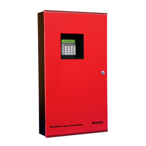
Detnov CCD-020 User manual

EN
CCD-020 / CCD-040
Conventional re detection control panel
INSTALLATION MANUAL


CONTENTS
1. Introduction ..............................................................................7
1.1. About this manual .................................................................................. 7
1.2. European Standards ............................................................................. 8
1.3. Explicitdenitions .................................................................................. 9
1.4. Characteristics of the control panel ................................................... 10
1.5. Inventory ................................................................................................ 10
1.6. Damage to the unit ............................................................................... 11
1.7. Requirements ........................................................................................ 11
1.7.1. Assembly notes ....................................................................................................11
1.7.2. Installation notes ................................................................................................. 12
1.7.3. Operating conditions ........................................................................................... 12
1.7.4. Disclaimer ............................................................................................................ 13
2. General description of the series ..........................................14
3. Assembly guide ......................................................................16
3.1. Pre-installation checks ......................................................................... 16
3.2. Installation steps ................................................................................... 17
3.2.1. Removing the front cover .................................................................................... 17
3.2.2. The control panel's wiring .................................................................................... 17
3.2.3. Location of the control panel on the wall ............................................................. 18
3.2.4. Fixing the control panel to the wall ...................................................................... 18
3.2.5. Language selection ............................................................................................. 19
4. Wiring guide ............................................................................20
4.1. Zone wiring ............................................................................................ 20
4.1.1. Detector wiring .................................................................................................... 20
4.1.2. Manual call point wiring ....................................................................................... 21
4.2. Sounder wiring ............................................................................. 21
4.2.1. Sounder timer ...................................................................................................... 22
4.3. Wiring of 24 VDC auxiliary output ...................................................... 22
4.4. Wiring of voltage-free relay output ..................................................... 22

4.5. Power supply wiring ............................................................................. 23
4.5.1. Battery wiring ....................................................................................................... 23
4.5.2. Wiring to the mains .............................................................................................. 23
5. Start-up guide ..........................................................................26
5.1. Systemverication ............................................................................... 26
5.2. The system's power supply ................................................................. 26
5.3. Testing the system ................................................................................ 27
6. User guide ...............................................................................28
6.1. Indicator lights .............................................................................. 28
6.2. Audible indicators ......................................................................... 30
6.3. Control keys ................................................................................. 30
6.4. Operating modes .................................................................................. 31
6.4.1. Standby mode ..................................................................................................... 31
6.4.2. Alarm mode ......................................................................................................... 31
6.4.3. Fault mode .......................................................................................................... 32
6.4.4. Disconnected mode ............................................................................................. 33
6.4.5. Test mode ............................................................................................................ 33
6.4.6. Out of service mode ............................................................................................ 34
6.4.7. System fault mode ............................................................................................... 34
6.5. What to do in the event of an alarm ................................................... 35
7. Maintenance guide ..................................................................36
7.1. The user ................................................................................................. 36
7.1.1. Daily checks ........................................................................................................ 36
7.1.2. Monthly checks .................................................................................................... 36
7.2. The maintenance company ................................................................. 36
7.2.1. Weekly checks .................................................................................................... 36
7.2.2. Yearly checks ...................................................................................................... 36
8. Troubleshooting ......................................................................37
9. Characteristics ........................................................................38


7
EN
1. Introduction
1.1. About this manual
TheCCD-020/040seriesofconventionalrealarmcontrolpanelsisdesignedforsmalland
medium-sized facilities that require a simple detection system, such as small businesses,
schools, warehouses, etc. These control panels have been approved according to the
EN54-2(UNE23007-2)Europeanstandardforredetectionandalarmcontrolpanels
and the EN54-4 (UNE 23007-4) standard for power supply systems, making them an
investment in safety and peace of mind.
The purpose of this manual is to provide the user with all of the descriptions regarding
procedures and technical details necessary to carry out the assembly, connection and
start-up of CCD-020/040 control panels quickly and safely.
• READ ALL INSTRUCTIONS carefully and fully before starting to install the control
panel.Ifyouhaveanyqueriesregardingtheassembly,installationorcongurationof
the control panel, please contact your distributor or technical support service before
continuing to install the equipment.
• STORE THIS MANUAL in a place that is easy to access as it contains important
instructions regarding installation and use.
• MAKE SURE that you have the necessary knowledge and the right tools to connect
this control panel. Using unsuitable tools may damage the unit and jeopardise the
integrity of the system. Bear in mind that these control panels must be installed
by qualied sta and must meet the design and installation requirements that are
applicable,suchastheUNE23007-14standardandanylocalandindustry-specic
regulations.
• KEEP THE PACKAGING BOX as you may need it if you have to send the control
panel to the technical support service.
Each step in the CCD-020/040 control panel's assembly, connection and start-up process
includes descriptions and detailed graphics to make it easy to follow the instructions.

8
EN
1.2. European Standards
This panel has the CE marking to indicate that it meets the requirements of the following
EU directives.
• 305-2011 CPR Construction Products Regulation.
• 2014/30/EU EMC Electromagnetic Compatibility Directive.
• 2014/35/EU LVD Low Voltage Directive.
In addition to these directives, the manufacturing of this control panel complies with the
following European directives for manufacturing and waste management:
• 2011/65/EU (RoHS), European standard on the restriction of the
use of certain hazardous substances (lead, mercury, cadmium,
hexavalent chromium, polybrominated biphenyls, polybrominated
diphenyl ethers) in small and large household appliances,
computer and telecommunications equipment, consumer
electronicdevices,lightingxtures,electricalandelectronictools,
toys, leisure and sports equipment, medical devices, control and
monitoring instruments, including industrial control instruments, vending machines and
other equipment not included in the above categories.
• 2012/19/EU (WEEE), European standard on the recycling of non-
disposable products, such as unclassied municipal waste within the
area of the European Union. When purchasing an equivalent new unit,
return this product to your local supplier or dispose of it at the collection
points designated for this purpose in order to facilitate its appropriate
recycling.

9
EN
1.3. Explicit denitions
The procedures described in this manual include warnings and notes to guide the user
on how to adopt methodical and safe working practices during installation, start-up and
conguration.
Please heed the warnings in this manual as incorrect use or improper installation may
lead to an equipment malfunction, damage to the unit and even injury.
Thesewarningsareclassiedin3levels,accordingtotheirimportance:
WORD DEFINITION
⚠WARNING! Riskofinjury,reorelectrocution.
CAUTION Ignoring this instruction may damage the unit or
jeopardise the integrity of the system.
NOTE Advice that makes the process easier

10
EN
1.4. Characteristics of the control panel
TheCCD-020/040seriesofconventionalcontrolpanelshasbeencertiedtomeetthe
requirements of the EN54-2 (UNE 23007-2) and EN54-4 (UNE 23007-4) standards. This
range of control panels features:
• 2 detection zones (CCD-020) / 4 detection zones (CCD-040)
• 2 sounder outputs
• 1 alarm output
• 1 fault output
• 1 24 V auxiliary output
1.5. Inventory
Before unpacking the unit, check that the packaging has no dents, holes or other damage.
After unpacking the control panel, before installing it in the selected place, check that it
is not damaged in any way.
Check that the equipment contains the following:
• One CCD-020 or CCD-040 control panel
• One end-of-line resistor for each detection zone (value = 4K7 ohms)
• Two end-of-line resistors for the sounder (value = 4K7 ohms)
• One 5x20 4 A fuse
• One 5x20 0.5 A fuse
• Two keys
• One quick guide
• A wire jumper to connect the batteries in series
• An insertable sheet in multiple languages
NOTE: If the control panel is damaged or any of these elements
are missing, do not continue with the installation and contact your
distributor.

11
EN
1.6. Damage to the unit
If the unit is damaged, any accessory is missing or you have queries regarding the
explanations in this manual:
• Contact your technical support service or distributor. If necessary, they will send you
a document to manage your RMA request.
• Note down the invoice or delivery note number and whether the unit is still under
warranty.
• Note down all of the relevant details in your RMA request: date of receipt of the
product, detailed description of the fault, condition of the packaging, etc., and send it
to your supplier.
• If you need to send the product to your supplier, use the original packaging, where
possible.
1.7. Requirements
1.7.1. Assembly notes
KNOWLEDGE: Make sure that you have the necessary mechanical and electrical
knowledge of re detection systems to install this control panel and connect it to the
detection system and mains supply.
TOOLS: To assemble the control panel, you will need:
• An electric drill
• A cross-head screwdriver (Phillips or Pozidrive)
• Asmallat-headscrewdriverfortheterminals
• Insulating tape
• Measuring tape
• A cutter
• 4 lag screws, 3.6-4.1 mm in diameter and 40 mm long
• 4 DNP6 wall plugs (6 mm in diameter)
• A multimeter
• PG13 cable glands (the quantity necessary for the number of outputs/inputs that are
going to be used)
• A crown drill bit with a diameter of 18 mm

12
EN
1.7.2. Installation notes
This control panel has been designed to comply with the EN54 standard, so it must be
installed in accordance with the requirements of that standard.
⚠WARNING!: Failing to meet these requirements may cause
a system malfunction and constitute a breach of the EN54
standard.
CERTIFIED INSTALLER:Makesurethatthepersoninstallingthepanelisacertied
installer. It is also essential that the system of which this control panel is part has been
designedbyqualiedstaandcomplieswiththeUNE23007-14standard,anymunicipal
by-laws and any regulations in force in the place where the control panel is being installed.
1.7.3. Operating conditions
Before installing the CAD-020/040 series control panel, you must check that a number
of conditions are met:
⚠WARNING!: Do not install the control panel if any of the
following conditions are not met.
• The ambient temperature must be between -5ºC and 40ºC.
• The relative humidity must be between 5% and 95%, non-condensing.
• The control panel must be installed in a place where it is not subjected to vibrations.
• The control panel's controls must be accessible.
• The control panel must be properly earthed. The control panel may operate incorrectly
or be damaged if it is subjected to induced transient electrical discharges.
• Thewallonwhichthecontrolpanelisinstalledmustbesucientlyat,toavoidany
deformation of the case and subsequent problems with closing it.
• Do not install the control panel in a place where it is dicult to access it or its
connections.
NOTE:TheCAD-020/040seriescontrolpaneliscertiedto
operate under certain conditions; exceeding the operating ranges
of the control panel may result in the warranty being voided.

13
EN
1.7.4. Disclaimer
CCD-020/040redetectioncontrolpanelshavebeendesignedtoworkunderthemost
demanding operating conditions and they can also be adapted to any type of system,
thanks to their versatility.
Rememberthatincorrectassembly,improperinstallationorpoorcongurationoftheunit
may jeopardise the integrity of the system and is not the responsibility of the control panel
manufacturer.
The condition of the detector wiring is also not the responsibility of the control panel
manufacturer.
The accuracy of the contents of this manual is the most important aspect and has been
thefocusofallofoureorts.Nevertheless,themanufacturerreservestherighttochange
the information without prior notice.
You can access the latest version of this manual at www.detnov.com

14
EN
2. General description of the series
1. MAINS TERMINAL BLOCK
2. ZONE CONNECTORS
3. ALARM OUTPUT
4. FAULT OUTPUT
5. SOUNDER OUTPUT 1
6. SOUNDER OUTPUT 2
7. 24 V AUXILIARY OUTPUT
8. LOCK KEY
9. CONTROLS
10. INDICATOR LIGHTS
11. 2 A FUSE OF BATTERY
12. 0.5 A FUSE OF 24 V AUXILIARY OUTPUT
13. 0.5 A FUSE OF SOUNDER 2
14. 0.5 A FUSE OF SOUNDER 1
15. SOUNDER DELAY CONFIGURATION
16. START PUSH-BUTTON WITH BATTERY
17. BATTERY CONNECTOR
18. BATTERY WIRE
19. BATTERY JUMPER
20. BATTERIES
1
9
18
16
20
19
+ -
+ -
z1 + -
z2 + -
z3 + -
z4
c nc na
alarm
c nc na
fault snd1 + -
snd2 + -
24v aux
21 3 4
2 3 5 7
64
19 15 14
12
13
11
10
8

15
EN

16
EN
3. Assembly guide
Read this chapter carefully and familiarise yourself with the various parts of the control
panel,itsinternalcomponentsanditscongurationbeforestartingtoinstallthesystem.
CAUTION: Failing to follow the instructions in this chapter may
lead to the unit being damaged.
3.1. Pre-installation checks
It is also essential that the detection system of which this control panel is part has been
designedbyqualiedstaandcomplieswiththeUNE 23007-14 standard, any municipal
by-laws and any regulations in force in the place where the control panel is being installed.
In the unlikely event that the unit arrives damaged, contact your distributor as detailed
in SECTION 1.6.
Before connecting anything, use the multimeter to check the resistance of the zone lines
and the sounder lines. You can check the resistance of each line by measuring it on the
+ and - terminals. If the end-of-line resistor is connected, the value should be 4K7 ohms.
+ -
+ - + - + - + -
c nc na c nc na
+ - + -
4K7 resistor
4K7 resistor
3 4
4K7 resistor
+ -
+ -
z1
+ -
z2
+ -
z3
+ -
z4
c nc na
alarm
c nc na
fault snd1
+ -
snd2
+ -
24v aux
4K7 resistor
1 2 1 2 3 4 1 2 3 4
+ -
z1
Ω

17
EN
3.2. Installation steps
3.2.1. Removing the front cover
To access the inside of the control
panel, remove the 2 screws from
the front part in the lower area.
After unscrewing them, remove
the cover.
3.2.2. The control panel's wiring
Before mounting the control panel, establish where the necessary wires will pass through
(the lines for the zones, sounders and connection to the mains supply).
The sounder and zone lines should
be connected via the right side of
the case (A), either by making
holes at the top using a crown
drill bit (drill the necessary holes
and use PG13 cable glands) or by
breaking through the rear wall.
Use the openings on the left side
of the case to feed in the wires for
the mains supply, either through
the opening at the top (B) or the
hole at the back (C).
AB
C
CAUTION: Be careful when drilling the housing to make a hole
for the lines, you may damage the control panel's electronics.

18
EN
3.2.3. Location of the control panel on the wall
Choose a place that is easy to access and free of obstacles, where the indicator
lightscanbeseenwithoutdicultyandthecovercanberemovedeasily.The
controlpanelmustbeplacedataheightof1.5mfromtheoor.
3.2.4. Fixing the control panel to the wall
Toxthecontrolpaneltothewall,usetherearhousingasatemplate.Todo
this, hold it against the wall in the desired place and mark the position of the
xingholes,makingsurethatthehousingislevel.
CAUTION: Do not use the rear housing as a guide when you are
going to drill the holes, it may cause irreparable damage to the unit.
Drill the holes into the wall and insert the wall plugs. Use the wall plugs recommended in
SECTION 1.7.1. and screw in the housing through the holes in the case, using the screws
recommended in that point.
235 mm
225 mm
188 mm
8 mm

19
EN
3.2.5. Language selection
CAD-020/040 conventional control panels allow you to customise the language by
using the inserts included on the language sheets that are supplied. Select the required
language and insert the sheet into the corresponding slot located on the lower left side
of the keypad. These locations are marked with the letters A, B and C. To prevent any
movement of the B and C inserts, secure them at the bottom with adhesive tape.
ENGLISH ALARM
FAULT
DISABLE/
TEST
ATEST
ACTIVATE
SOUNDERS
MUTE
SOUNDERS
MUTE
CONTROL
PANEL
RESET
SYSTEM
FAULT
SUPPLY
FAULT
OUT OF
SERVICE
TIMED
SOUNDERS
SOUNDERS
FAULT/DISABLED
B
SERVICE
ALARM
DISABLE
FAULT
C
+ -
+ -
z1 + -
z2 + -
z3 + -
z4
c nc na
alarm
c nc na
fault snd1
+ -
snd2
+ -
24v aux
21 3 4

20
EN
4. Wiring guide
Thetypesofwiringthatyouwillnormallyndinaconventionalredetectionsystemare
listed below.
4.1. Zone wiring
CCD-020/040 series control panels are designed to manage the signals of up to 32
detectors or 32 manual call points for each zone, as recommended in the EN54 and UNE
23007-14 standards.
Azone'swiringshouldbegininthecontrolpanel'sterminalblockandnishintheend-of-
line resistor (4K7 ohms). If any zone is not going to be used, it is necessary to place the
end-of-line resistor (4K7 ohms) in the terminals of this zone's terminal block so that the
system does not detect a fault.
According to the standards, it is not permitted to make a star-connected wire shunt or
install the end-of-line resistor on the terminal block if that zone is in use.
4.1.1. Detector wiring
Conventional re detection control panels are compatible with DETNOV's range of
conventional detectors. We cannot guarantee that the system will work correctly with
devices made by another manufacturer.
As shown in the above drawing, the + is connected to contact no. 1 (through which
it enters and leaves), while the negative terminal is connected with the line entering
through contact no. 4 and leaving through contact no. 3 to the following detector. At the
end of the line you must place a 4K7 ohm resistor.
+ -
+ - + - + - + -
c nc na c nc na
+ - + -
4K7 resistor
4K7 resistor
3 4
4K7 resistor
+ -
+ -
z1
+ -
z2
+ -
z3
+ -
z4
c nc na
alarm
c nc na
fault snd1
+ -
snd2
+ -
24v aux
4K7 resistor
1 2 1 2 3 4 1 2 3 4
+ -
z1
This manual suits for next models
1
Table of contents
Other Detnov Control Panel manuals
