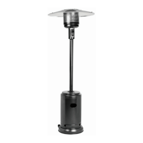
Brander TR6029 NG Operating instructions

PATIO INFRARED HEATER
THIS APPLIANCE IS CERTIFIED FOR OUTDOOR USE ONLY
USER INSTALLATION AND OPERATION GUIDE
INDEX
General and specifications ................................2-3
Safety and caution ................................................4
Tool and accessory requirements.............................. 5
Assembly instructions......................................6-7
Leak testing the connections ..............................8
Choosing a location for the heater...........................9
Operating the heater..........................................10
Storage and maintenance.....................................10
CAREFULLY READ THIS GUIDE AND ALL SAFETY INFORMATION
ITEM NO.: TR6029 NG (SS - NG) ITEM NO.:
TR6026 NG (BLACK -NG)
TRADEX SUPPLY LTD.
MADE IN CHINA FOR TRADEX SUPPLY LTD. CALGARY,
ALBERTA, CANADA
1
Troubleshooting.....................................................11

WARNING & SAFETY RULES
PLEASE READ THE FOLLOWING SAFETY RULES
PRIOR TO OPERATION OF THE HEATER
For Your Safety
If you smell gas:
1. Shut off gas supply to the appliance.
2. Extinguish any open flame.
3.
If odour continues, immediately call your gas supplier or your
fire department.
For Your Safety
1. Do not store or use gasoline or other flammable vapors and
liquids in the vicinity of this or any other appliance.
2. LP cylinders not connected for use shall not be stored in the
vicinity of this or any other appliance.
WARNING:
For Outdoor Use Only
WARNING:
Improper installation, adjustment, alteration, service or
maintenance can cause injury or property damage. Read the
installation, operating and maintenance instructions thoroughly
before installing or servicing this equipment.
2

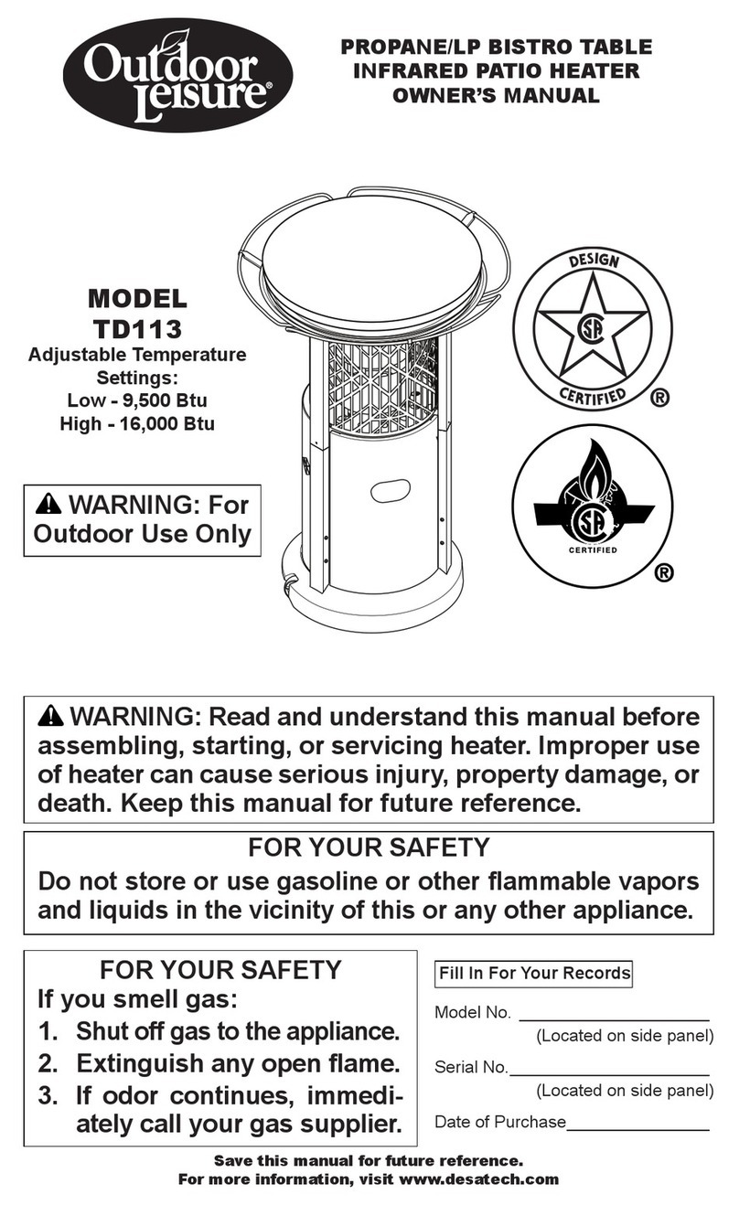
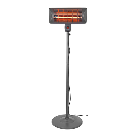
This appliance is an infrared transportable heater.
The burner is controlled and adjusted by the gas control knob.
Gas supply is controlled by the gas supply source. The burner is made of stainless
steel. Heat diffusion is assisted by the reflector above.
Technical Specifications:
.
.
Maximum output:
.Minimum output:
NG
7.0" W.C.
45,000 BTU/H
25,000 BTU/H
For Your Safety
1. If you smell gas:
a. Turn off gas supply at gas source.
b. Extinguish all open flame.
c. Proceed to a leak test, see bottom of page 4.
d. If you still smell gas, shut-off heater completely and gas valve at cylinder. Call the
retailer where you purchased the heater or contact a gas appliance service centre or
your gas supplier.
2. Never store or handle gas, or any other inflammable vapours or liquids in the vicinity of your
patio heater or any gas appliance.
CAUTION
-Faulty installation, modifications, repairs or maintenance to this appliance may be the cause
of injury or damage to property.
-Carefully read this user guide before assembling and preparing the heater.
-Keep this guide for future reference.
Operating pressure:
3

CAUTION
-DO NOT operate the heater in an explosive environment. Keep this appliance away from
areas where gas is stored, or other vapours and flammable liquids are present.
-Before use, verify that no part of this heater is damaged and inspect gas hose.
-Never use the heater without the reflector installed.
-Respect minimum clearances from combustibles as seen in Figure 10.
-Always place heater on a level, stable and hard surface.
-NEVER move the heater while it is operating or still hot.
-This heater is to be used outdoors only.
-Never clean with abrasive, corrosive or flammable cleaners.
-Do not paint the heater or some of its parts.
-The gas sources must be turned-off at all times when heater is not in use.
-Children and adults should be made aware of hot surfaces on the heater.
-Clothing and other accessories or objects are not to be hung on the heater, laid on or near it
to dry. Do not obstruct the ventilation opening (hand hole) on cylinder cover.
-Installation, maintenance and repair of this heater should always be performed by a qualified
gas technician.
Leak Testing The Connections
When the heater is partially assembled (step F), perform a leak test on all connections and
hose BEFORE lighting for the first time and after all repairs or maintenance on the heater. To
test for leaks, mix equal parts water and soap in a spray bottle and apply to connections and
hose. If there is a leak, bubbles will start to appear. Repeat leak test whenever maintenance or
service is required.
NEVER LEAK TEST WITH AN OPEN FLAME, NOR SMOKE WHILE TESTING
1. Ensure that heater gas control knob is fully closed by turning completely clockwise.
2. Open gas supply source.
3. Generously apply soapy solution to all connections and hoses.
4. If you detect bubbles, there is a leak. Turn-off gas supply source completely.
5. Re-tighten the leaking connection and repeat leak test process.
If the leak cannot be repaired permanently, close cylinder valve completely and contact the
retail outlet where you purchased the heater, your gas supplier, a qualified gas technician, or
the local fire department.
FOR YOUR SAFETY YOU SHOULD REGULARLY TEST FOR LEAKS
4

PARTS LIST
1. Base
2. Safety label
3. Weighted box
4. Pole
5. Gas control
6. Match access opening
7. Burner assembly
8. Reflector
9. Wheels (see page 9)
TOOLS AND EQUIPMENT REQUIRED
10 and 13 mm keys
Adjustable wrench
Philips screwdriver,medium blade
Leak test solution:mix 50/50 water and soap
6 x Bolts M6 X 55
4 x Bolts M8 X 55
4 x Bolts M6 X 10
6 x Large steel washers
6 x Bolts M6
4 x Bolts M8
4 x Mechanical screws 3/16”
3 x Butterfly nut
figure 1
56
7
8
5

Prior to disassembling the base as detailed in step (A). Take note of the black plate that is attached to the
bottom of your weighted base.
This plate will act as a washer for the nuts and will assist in increasing the stability of the pole.
Once the nuts and bolts are removed, ensure that this black plate remains in place.
Prior to attaching the post to the top of the weighted base (B). Ensure that the black plate is installed properly
at the bottom of the base.
Once the pole is attached to the base with the three nuts and bolts provided, the bottom of the base should
look like photo (iii). Ensure the bolts are not over tightened to the plate.
Once all seven nuts and bolts are properly installed, the bottom of your base with the washer should look like
picture (iv). Ensure that bolts are snug, but not over tightened or it will warp the black plate.
ADD
E
NDUM
T
O
BRAND
E
R
PATI
O
H
E
AT
E
RS
-
TR6026NG
,
TR6029NG
T
hank you for your purchase of the
B
rander
P
atio
H
eater.
P
rior to assembling this patio heater, please read
through these additional in
-
depth instructions.
T
his will improve the stability of your patio heater.
6

ASSEMBLY INSTRUCTIONS
Figure 2
Figure 5
A. Disassemble the base . Unscrew 4pcs M8 bolts and
4pcs M8x55 bolts from weighted box and base (Figure 2).
Do not remove bottom black plate (please see page 6,
Figure (i & ii) to identify black plate). This plate will act
as a washer for the nuts and will assist in increasing the
stability of the pole.
B. Place the post on the top of the weighted box, with black
plate attached on bottom. Then connect them with 6pcs
M6x55 bolts and 6pcs M6 bolts (Figure 3).
C. Attach the base over the post to the weighted bo x with 4pcs
M8 bolts and 4pcs M8x55 bolts (Figure 4). Do not over-
tighten the bolts, or the black plate will warp underneath.
D. Attach natural gas hose (not included with heater) to
heater head with a wrench. Leak-test connection. Run other
end of hose down pole and out lower access hole (Figure 5).
Figure 3
Figure 4
7
Black Plate

E. Fasten heater head (with hose now attached and leak-
tested) to the top of pole.. Tighten securely using 4 pcs
M6X10 (Figure 6). Do not remove any bolts.
Figure 6
F.
**MANDATORY LEAK TEST REQUIRED** Refer to page 4, see header:
“LEAK TESTING THE CONNECTIONS“
Proceed to test gas system as indicated on page 4. Make sure to test hose and all
connections for leaks. Lift burner head and test hose connection to burner head.
G. Place burner head so control button is vertically aligned with the instructions label on the
post. Place 1 steel washer over each of the 3 bolts (Figure 7). Install reflector over burner
head through bolts. Place steel washers over each bolt (Figure 8). Secure reflector with
wing nuts.
Figure 8Figure 7
8

H. Installing Wheels
(1) SCREW____________8 Pieces
(2) NUT_______________2 Pieces
(3) WHEEL ____________2 Pieces
(4) BRACKET__________2 Pieces
(5) BOLT______________2 Pieces
(6) BASE ____________ 1 Pieces
(7) NUT_______________8 Pieces
Figure 9
I. Choosing A Location For The Heater
Caution
When objects are left under a heater in operation, they will be subject to radiant
heat and this could result in damage.
This heater is certified for outdoor use only.
J.
CLEARANCES FROM COMBUSTIBLES
Respect clearances as shown:
-Sides of reflector: 24 inches (61CM)
-Above reflector: 18 inches (46CM)
Figure 10
-Provide fresh air ventilation at all times.
-Respect minimum clearances to combustibles as shown in Figure 10.
-Install heater on level, solid, and stable ground.
-Do not install in an explosive environment. Keep away from areas where gas,
vapours, or flammable liquids are stored or used.
-In case of high winds, shut off the heater and gas supply. Remove reflector
and store the heater.
-Do not move the heater when hot.
9

1. Ensure control knob on heater is in the OFF position.
2. Open valve for fuel supply.
3. Turn control knob to position. Press igniter button multiple times to light burner. When
burner is lit, continue to press and hold down control knob for 30 seconds. This engages the
thermocouple. If burner does not light, release control knob and turn it clockwise to the OFF
position. Wait 5 minutes. Repeat steps 2 to 3.
4. If igniter does not work properly, you may light heater manually by inserting a match through
the opening at base of burner (6), as shown in figure 1.
5. Turn control knob counter clockwise to adjust flame to desired temperature for comfort
Operating The Heater
To Turn Off
1. Turn control knob fully clockwise.
2. Turn off gas supply at source.
3. If heater is not used for long periods, remove from gas source.
Preventative Care and Maintenance
To ensure long-lasting enjoyment of your Patio Heater, the burner should be inspected
regularly for debris such as insects and spider webs.
Have Heater Inspected If
-You smell gas combined with yellow flame tips on burner
-Heater does not provide expected heat capacity
-Abnormal sounds occur during operation
Also...
-Periodically check for leaks in the system or immediately when you smell gas.
-In case a leak is detected, extinguish all open flames in the area.
-Never leak test while smoking or with an open flame.
-If you cannot repair a leak, ensure gas supply is turned OFF and contact the retailer where
you purchased the heater, a qualified technician, or your gas supplier.
-Do not modify this heater in any way.
-Replacement parts must only be with original parts.
-The installation of this appliance should be performed by a certified gas technician in
conformity with all building and municipal codes.
10

Trouble Shooting:
Problem Possible Cause Solution
Blockage in orifice Clean or replace orifice
Air in gas line Burner may take 1-8 minutes to light
after natural gas has been
connected.
Thermocouple has
carbon build-up on it Clean thermocouple tip.
Igniter fails Use match to light the burner. Obtain
new lighter and replace.
Heater control knob not fully
depressed
Depress heater control knob firmly
in lighting position.
Gas pressure is low Check gas supply.
Blockage in orifice Clear blockage
Burner won’t light
Control knob is not in
ON Position Turn control knob to ON
Gas pressure is low Check connection to gas
supply.
Blockage in orifice Clear blockage
Flame won’t light
Control knob is not in
ON position
Turn control knob to ON
Supply hose is bent or kinked Straighten hose
Control knob is fully ON Check burner and orifice for blockage
Carbon build-up Dirt or film on reflector and
emitter
Remove blockage and clean burner
inside and outside.
Thick black
smoke from
burner of light
Blockage in burner or in light
gas passages
Remove blockage and clean burner
inside and outside.
Warranty:
1 Year Manufacturer's Warranty
Burner flame is low
Note: Do NOT
operate heater
below -18C
11
- Only applicable on manufacturer's defects
- Only applicable to parts
- Does not include labour
- Please contact retailer you purchased your heater from and provide receipt
This manual suits for next models
1
Table of contents
