DEUTSCHMANN AUTOMATION LOCON 200 User manual
Instruction manual
Electronic cam control
LOCON 200
Deutschmann Automation GmbH & Co. KG
www.deutschmann.com | wiki.deutschmann.de

Manual Art.-No. V3492E

13.11.18 Instruction manual LOCON 200 V. 4.6 3
Deutschmann Automation GmbH & Co. KG
Foreword
This operating manual provides users and OEM customers with all the information necessary for
the installation and operation of the product described in this manual.
All details contained in this manual have been checked carefully, however, they do not represent
an assurance of product characteristics. No liability can be accepted for errors. DEUTSCHMANN
AUTOMATION reserves the right to carry out alterations to the described products in order to
improve the reliability, function or design thereof. DEUTSCHMANN AUTOMATION only accepts
liability to the extent as described in the terms and conditions of sale and delivery.
All rights reserved, including translation. No part of this manual may be reproduced or proces-
sed, copied or distributed in any form whatsoever (print, copy, microfilm or any other process)
without written permission from DEUTSCHMANN AUTOMATION.
Bad Camberg, November 2018

Deutschmann Automation GmbH & Co. KG
4 Instruction manual LOCON 200 V. 4.6 13.11.18

13.11.18 Instruction manual LOCON 200 V. 4.6 5
Deutschmann Automation GmbH & Co. KG
1Introduction . . . . . . . . . . . . . . . . . . . . . . . . . . . . . 9
1.1 On this manual . . . . . . . . . . . . . . . . . . . . . . . . . . . . . . . 9
1.1.1 Symbols . . . . . . . . . . . . . . . . . . . . . . . . . . . . . . . . . . . . 9
1.1.2 Concepts . . . . . . . . . . . . . . . . . . . . . . . . . . . . . . . . . . . 9
1.1.3 Suggestions . . . . . . . . . . . . . . . . . . . . . . . . . . . . . . . . . . 9
1.2 From the mechanical system to an electronic system . . . . . . . . . . 10
1.3 Deutschmann Automation’s range of products . . . . . . . . . . . . . . 10
2EMC Directives for products of Deutschmann Automation . . 11
3Basic unit LOCON 200 . . . . . . . . . . . . . . . . . . . . . . 12
4Mechanical installation instructions . . . . . . . . . . . . . . . 13
4.1 Installation . . . . . . . . . . . . . . . . . . . . . . . . . . . . . . . . . 13
4.2 Housing dimension . . . . . . . . . . . . . . . . . . . . . . . . . . . . 13
4.3 Mounting / dismounting of the extension module . . . . . . . . . . . . . 14
4.4 Connecting lines . . . . . . . . . . . . . . . . . . . . . . . . . . . . . 14
4.4.1 Connecting lines without shield . . . . . . . . . . . . . . . . . . . . . . . . 15
4.4.2 Connecting shielded lines . . . . . . . . . . . . . . . . . . . . . . . . . . . 16
4.4.3 Grounding clip . . . . . . . . . . . . . . . . . . . . . . . . . . . . . . . . . 17
5Electrical connections LOCON 200 . . . . . . . . . . . . . . . 18
5.1 Front view LOCON 200 . . . . . . . . . . . . . . . . . . . . . . . . . . 18
5.2 Assignment X1 (communication) . . . . . . . . . . . . . . . . . . . . . 18
5.3 Assignment X2 (encoder connection SSI + incremental) . . . . . . . . . 19
5.4 Assignment X3 + X4 (I/Os) . . . . . . . . . . . . . . . . . . . . . . . . 19
5.4.1 Assignment X3 + X4 basic device . . . . . . . . . . . . . . . . . . . . . . . 19
5.4.2 Assignment X3 + X4 for the connection of a parallel absolute encoder . . . . 19
5.4.3 Assignment X3 + X4 for the connection of an incremental encoder 24V . . . 19
5.4.4 Assignment X2 - X4 for the connection of counting/direction inputs . . . . . 19
5.4.5 Assignment extension module I/O 8 . . . . . . . . . . . . . . . . . . . . . . 20
5.5 Signal description LOCON 200 . . . . . . . . . . . . . . . . . . . . . . 21
5.5.1 Status LED’s . . . . . . . . . . . . . . . . . . . . . . . . . . . . . . . . . . 22
5.6 External program selection . . . . . . . . . . . . . . . . . . . . . . . . 22
5.6.1 Applying the corresponding voltages. . . . . . . . . . . . . . . . . . . . . 22
5.6.2 Generating the acceptance edge . . . . . . . . . . . . . . . . . . . . . . . 23
5.6.3 Graphical representation of program selection . . . . . . . . . . . . . . . . 23
5.7 Installation and initiation of LOCON 200 . . . . . . . . . . . . . . . . . 23
5.7.1 Connection of the supply voltage . . . . . . . . . . . . . . . . . . . . . . . 23
5.7.2 Connection of the inputs and outputs . . . . . . . . . . . . . . . . . . . . . 24
5.7.3 Connection of the serial RS232 interface . . . . . . . . . . . . . . . . . . . 24
5.7.3.1 Interface-switch (up to Firmware < V3.0) . . . . . . . . . . . . . . . . . . 24
5.7.3.2 Interface switch (Firmware V3.0 and higher) . . . . . . . . . . . . . . . . 25
5.7.4 Connection of the DICNET bus interface . . . . . . . . . . . . . . . . . . . 25
6Configurations LOCON 200 . . . . . . . . . . . . . . . . . . . 26
6.1 WINLOC 32 - wizard . . . . . . . . . . . . . . . . . . . . . . . . . . . 26

Deutschmann Automation GmbH & Co. KG
6 Instruction manual LOCON 200 V. 4.6 13.11.18
6.2 TERM 6 or PROFIBUS . . . . . . . . . . . . . . . . . . . . . . . . . . 26
6.2.1 Reading and changing cam control parameters via TERM 6 . . . . . . . . 26
6.2.2 PROFIBUS . . . . . . . . . . . . . . . . . . . . . . . . . . . . . . . . . . 26
6.2.3 Possible error messages on the configuration . . . . . . . . . . . . . . . . 27
6.3 Configuration tree . . . . . . . . . . . . . . . . . . . . . . . . . . . . . 27
6.4 Configuration example . . . . . . . . . . . . . . . . . . . . . . . . . . 28
6.5 Parameter table . . . . . . . . . . . . . . . . . . . . . . . . . . . . . . 29
6.5.1 PNR_ENCODER_TYP - Encoder type . . . . . . . . . . . . . . . . . . . . 30
6.5.2 PNR_RESOLUTION_PER_TURN . . . . . . . . . . . . . . . . . . . . . . 30
6.5.3 PNR_ENCODER_INVERT . . . . . . . . . . . . . . . . . . . . . . . . . . 30
6.5.4 PNR_LANGUAGE - language selection . . . . . . . . . . . . . . . . . . . 30
6.5.5 PNR_DEADTIME_TYP . . . . . . . . . . . . . . . . . . . . . . . . . . . . 30
6.6 Configuration parameters LOCON 200 . . . . . . . . . . . . . . . . . . 30
6.6.1 Inputs and logic functions . . . . . . . . . . . . . . . . . . . . . . . . . . 30
6.6.2 SSI interface . . . . . . . . . . . . . . . . . . . . . . . . . . . . . . . . . 30
6.6.3 Incremental encoder . . . . . . . . . . . . . . . . . . . . . . . . . . . . . 31
6.6.3.1 Prescaler factor at incremental encoders . . . . . . . . . . . . . . . . . 31
6.6.3.2 Incremental counting/direction inputs . . . . . . . . . . . . . . . . . . . 31
6.7 Encoder monitoring . . . . . . . . . . . . . . . . . . . . . . . . . . . . 31
6.8 Logic functions (optional) . . . . . . . . . . . . . . . . . . . . . . . . . 32
6.8.1 Logic functions L200 . . . . . . . . . . . . . . . . . . . . . . . . . . . . . 32
6.8.2 Priorities of the logic operations . . . . . . . . . . . . . . . . . . . . . . . 32
6.8.3 Operation mode of the shift register . . . . . . . . . . . . . . . . . . . . . 32
6.8.4 Logic functions of the LOCON 200-Out I/O8 . . . . . . . . . . . . . . . . . 33
6.8.4.1 Example for the use of a shift register . . . . . . . . . . . . . . . . . . . 33
6.9 Count cam . . . . . . . . . . . . . . . . . . . . . . . . . . . . . . . . 34
6.10 Direction cams . . . . . . . . . . . . . . . . . . . . . . . . . . . . . . 34
6.11 Run-control-output . . . . . . . . . . . . . . . . . . . . . . . . . . . . 35
6.12 Dynamical zero offset . . . . . . . . . . . . . . . . . . . . . . . . . . . 35
6.13 Angle-time cam . . . . . . . . . . . . . . . . . . . . . . . . . . . . . . 35
6.14 Teach-in-cam (from firmware V3.4 on - version without PB only) . . . . 35
6.15 Offline programming . . . . . . . . . . . . . . . . . . . . . . . . . . . 36
6.16 Data backup and documentation on PC . . . . . . . . . . . . . . . . . 36
6.17 Program controller function (encoder simulation) . . . . . . . . . . . . . 36
6.18 Incremental output (generation of A/B-track) . . . . . . . . . . . . . . . 36
6.19 Mapping . . . . . . . . . . . . . . . . . . . . . . . . . . . . . . . . . . 37
6.20 PRESET and CLEAR . . . . . . . . . . . . . . . . . . . . . . . . . . . 37
7Networking terminals with cam controls and PCs . . . . . . . 38
7.1 RS232 link . . . . . . . . . . . . . . . . . . . . . . . . . . . . . . . . 38
7.2 RS485 link (DICNET) . . . . . . . . . . . . . . . . . . . . . . . . . . . 38
7.3 Cable type for DICNET . . . . . . . . . . . . . . . . . . . . . . . . . . 38
7.3.1 Earthing, shielding . . . . . . . . . . . . . . . . . . . . . . . . . . . . . . 39
7.3.2 Line termination at DICNET . . . . . . . . . . . . . . . . . . . . . . . . . 39

13.11.18 Instruction manual LOCON 200 V. 4.6 7
Deutschmann Automation GmbH & Co. KG
7.4 Comparison DICNET - RS232 . . . . . . . . . . . . . . . . . . . . . . 39
7.5 Connection examples . . . . . . . . . . . . . . . . . . . . . . . . . . . 40
7.5.1 DICNET link LOCON-TERM . . . . . . . . . . . . . . . . . . . . . . . . . . 40
7.5.2 RS232 link LOCON - TERM . . . . . . . . . . . . . . . . . . . . . . . . . . 41
7.5.3 DICNET link LOCON-TERM-PC . . . . . . . . . . . . . . . . . . . . . . . 42
7.6 Short instuction . . . . . . . . . . . . . . . . . . . . . . . . . . . . . . 43
8LOCON 200 with Modbus . . . . . . . . . . . . . . . . . . . . . 45
8.1 Angle-time-cam at LOCON 200 with Modbus . . . . . . . . . . . . . . . 49
9LOCON 200 with PROFIBUS . . . . . . . . . . . . . . . . . . . 50
9.1 GSD file . . . . . . . . . . . . . . . . . . . . . . . . . . . . . . . . . . 50
9.2 PROFIBUS Slave ID . . . . . . . . . . . . . . . . . . . . . . . . . . . 50
9.3 Error handling for the PROFIBUS version . . . . . . . . . . . . . . . . 50
9.4 Bus terminating resistor . . . . . . . . . . . . . . . . . . . . . . . . . . 50
10 Commissioning and self-test . . . . . . . . . . . . . . . . . . . 51
10.1 Commissioning of the terminal . . . . . . . . . . . . . . . . . . . . . . 51
10.1.1 Self-test of the terminal . . . . . . . . . . . . . . . . . . . . . . . . . . . . 51
10.2 Commissioning of the cam control . . . . . . . . . . . . . . . . . . . . 51
10.2.1 Self-test of the cam control . . . . . . . . . . . . . . . . . . . . . . . . . . 52
10.3 Configuration and initialization . . . . . . . . . . . . . . . . . . . . . . 52
10.3.1 LOCON 200 parameter table . . . . . . . . . . . . . . . . . . . . . . . . . 52
10.3.2 Parameter description . . . . . . . . . . . . . . . . . . . . . . . . . . . . . 53
10.3.2.1 Reverse rotational direction, encoder . . . . . . . . . . . . . . . . . . . . 53
10.3.2.2 Encoder type . . . . . . . . . . . . . . . . . . . . . . . . . . . . . . . . 53
10.3.2.3 Encoder resolution . . . . . . . . . . . . . . . . . . . . . . . . . . . . . 53
10.3.2.4 Counting range (only for incremental encoders) . . . . . . . . . . . . . . 53
10.3.2.5 Type of idle time compensation . . . . . . . . . . . . . . . . . . . . . . . 53
10.3.2.6 DICNET-device number (GNR) . . . . . . . . . . . . . . . . . . . . . . . 53
10.3.2.7 Zero offset (only for absolute encoders). . . . . . . . . . . . . . . . . . . 54
10.3.2.8 Scaling for speed display . . . . . . . . . . . . . . . . . . . . . . . . . . 54
10.3.2.9 Virtual encoder value (gear factor) . . . . . . . . . . . . . . . . . . . . . 54
11 Technical details . . . . . . . . . . . . . . . . . . . . . . . . . 55
11.1 Technical data LOCON 200 . . . . . . . . . . . . . . . . . . . . . . . . 55
11.2 Max. sum current LOCON 200 . . . . . . . . . . . . . . . . . . . . . . 55
11.3 LOCON 100 memory structure . . . . . . . . . . . . . . . . . . . . . . 56
11.4 LOCON 200 memory structure - Out I/08 (expansion module) . . . . . . 56
11.5 NT Module . . . . . . . . . . . . . . . . . . . . . . . . . . . . . . . . 57
11.6 Specification of the input levels . . . . . . . . . . . . . . . . . . . . . . 57
11.7 Specification of the output drivers . . . . . . . . . . . . . . . . . . . . . 57
11.8 Estimation of the cycle time . . . . . . . . . . . . . . . . . . . . . . . . 57
11.9 Switching accuracy of the Deutschmann cam controls . . . . . . . . . . 58
11.9.1 Switching accuracy (cycle time) of the basis . . . . . . . . . . . . . . . . . 58
11.9.2 Switching accuracy (cycle time) of IO8 . . . . . . . . . . . . . . . . . . . . 58

Deutschmann Automation GmbH & Co. KG
8 Instruction manual LOCON 200 V. 4.6 13.11.18
11.10 Function of the idle time compensation . . . . . . . . . . . . . . . . . . 59
11.10.1 Path-dependent idle time compensation . . . . . . . . . . . . . . . . . . . 59
11.10.2 Time-controlled idle time compensation . . . . . . . . . . . . . . . . . . . 60
11.10.3 Direct idle time compensation . . . . . . . . . . . . . . . . . . . . . . . . 60
11.10.4 Optimization of dynamics . . . . . . . . . . . . . . . . . . . . . . . . . . 60
11.11 Environmental specifications of cam controls of the LOCON series . . . 60
11.12 DICNET® . . . . . . . . . . . . . . . . . . . . . . . . . . . . . . . . . 60
11.13 Modbus . . . . . . . . . . . . . . . . . . . . . . . . . . . . . . . . . . 61
11.14 Communication interface . . . . . . . . . . . . . . . . . . . . . . . . . 61
11.15 Coding device numbers . . . . . . . . . . . . . . . . . . . . . . . . . . 62
12 Error messages . . . . . . . . . . . . . . . . . . . . . . . . . . 63
12.1 Error number 1..19 (irrecoverable error) . . . . . . . . . . . . . . . . . 63
12.2 Error number 20..99 (warning) . . . . . . . . . . . . . . . . . . . . . . 63
12.3 Error number 100..199 (serious error) . . . . . . . . . . . . . . . . . . 65
12.4 Error number 200-299 (terminal error) . . . . . . . . . . . . . . . . . . 66
13 Order Code . . . . . . . . . . . . . . . . . . . . . . . . . . . . 67
13.1 Cam control LOCON 200 . . . . . . . . . . . . . . . . . . . . . . . . . 67
13.1.1 Explanation of the order designation . . . . . . . . . . . . . . . . . . . . . 67
13.2 Scope of delivery . . . . . . . . . . . . . . . . . . . . . . . . . . . . . 67
13.2.1 Scope of delivery LOCON 200 . . . . . . . . . . . . . . . . . . . . . . . . 67
14 Servicing . . . . . . . . . . . . . . . . . . . . . . . . . . . . . . 68
14.1 Returning a unit . . . . . . . . . . . . . . . . . . . . . . . . . . . . . . 68
14.2 Internet . . . . . . . . . . . . . . . . . . . . . . . . . . . . . . . . . . 69

13.11.18 Instruction manual LOCON 200 V. 4.6 9
Deutschmann Automation GmbH & Co. KG Introduction
1 Introduction
1.1 On this manual
This manual documents installation, functions and operation of the Deutschmann unit specified
on the cover sheet and in the header.
1.1.1 Symbols
Particularly important text sections can be seen from the adjacent pictogram.
You should always follow this information since, otherwise, this could result in
malfunctions or operating errors.
1.1.2 Concepts
The expressions ‘LOCON’, ‘ROTARNOCK’ and TERM are frequently used throughout this Man-
ual with no further model specifications. In such cases, the information applies to the entire
model series.
1.1.3 Suggestions
We are always pleased to receive suggestions and wishes etc. and endeavour to allow for these.
It is also helpful if you bring our attention to any errors.
Introduction Deutschmann Automation GmbH & Co. KG
10 Instruction manual LOCON 200 V. 4.6 13.11.18
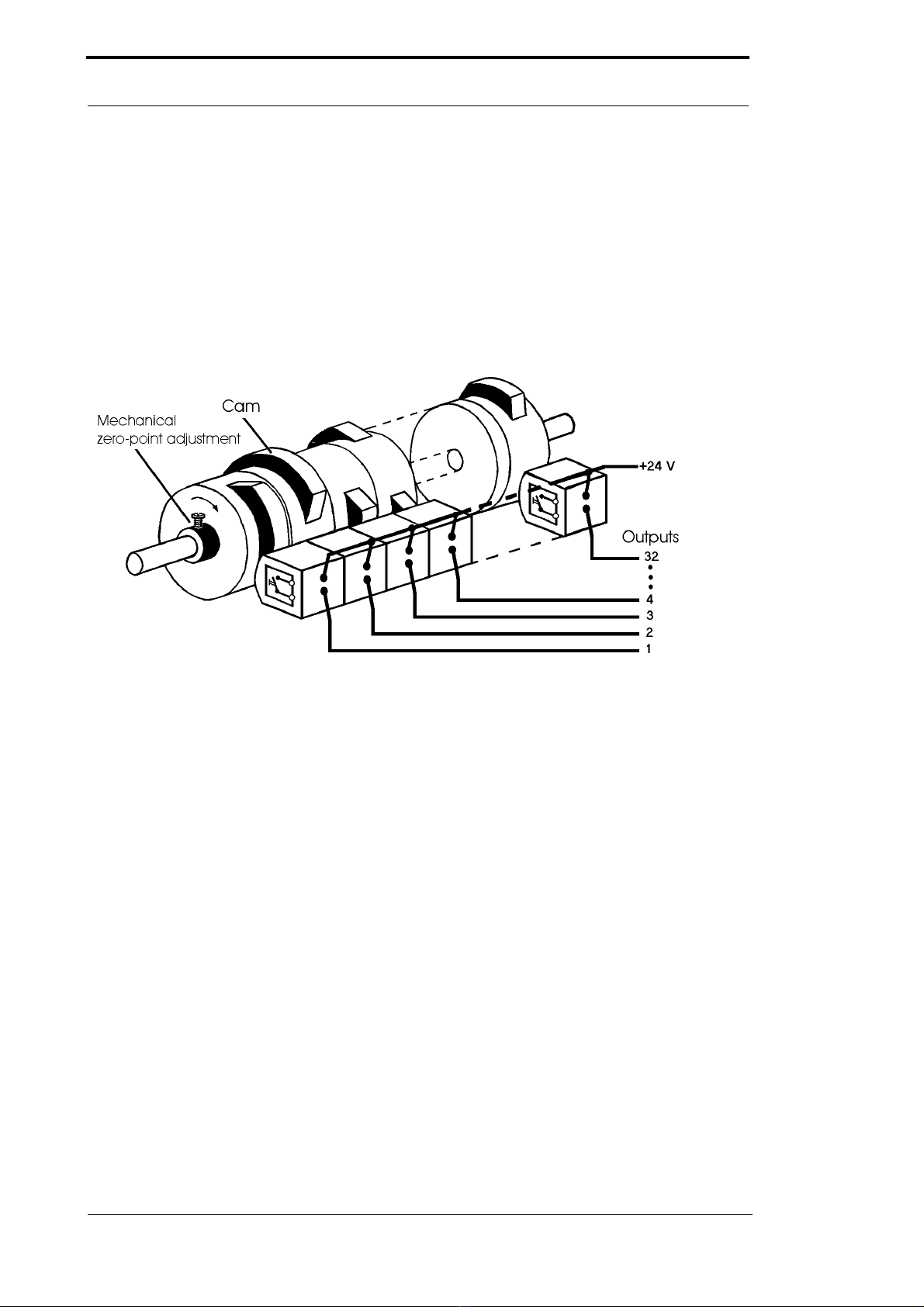
1.2 From the mechanical system to an electronic system
The purpose of electronic cam controls is not only to take the place of mechanical controllers but
to render their function more precise and simpler, to provide a universal range of application and
to reduce wear.
The mechanical cam control actuates a switch over sections of a circle, and this switch is closed
over the length of this section. Such a section is defined as a "cam".
Each switch represents one output. Several circuits arranged in parallel produce the number of
outputs.
Picture 1: Mechanical cam control
This basic principle has been adopted from the mechanical cam controls. A cam is programmed
for an output by entering a switch-on point and a switch-off point. The output is switched on
between these points.
Thanks to twenty years of experience, consistent further development and the use of ultra-mod-
ern technology, DEUTSCHMANN AUTOMATION has now become one of the leading suppliers
of electronic cam controls.
1.3 Deutschmann Automation’s range of products
A detailed and up-to-date overview of our product range can be found on our homepage at
http://www.deutschmann.de.

13.11.18 Instruction manual LOCON 200 V. 4.6 11
Deutschmann Automation GmbH & Co. KG EMC Directives for products of Deutschmann Automation
2 EMC Directives for products of Deutschmann Automation
The installation of our products has to be carried out considering the relevant EMC directives as
well as our internal instructions.
For more information see ’EMC Directives’ on our homepage at http://www.deutschmann.de.
Basic unit LOCON 200 Deutschmann Automation GmbH & Co. KG
12 Instruction manual LOCON 200 V. 4.6 13.11.18
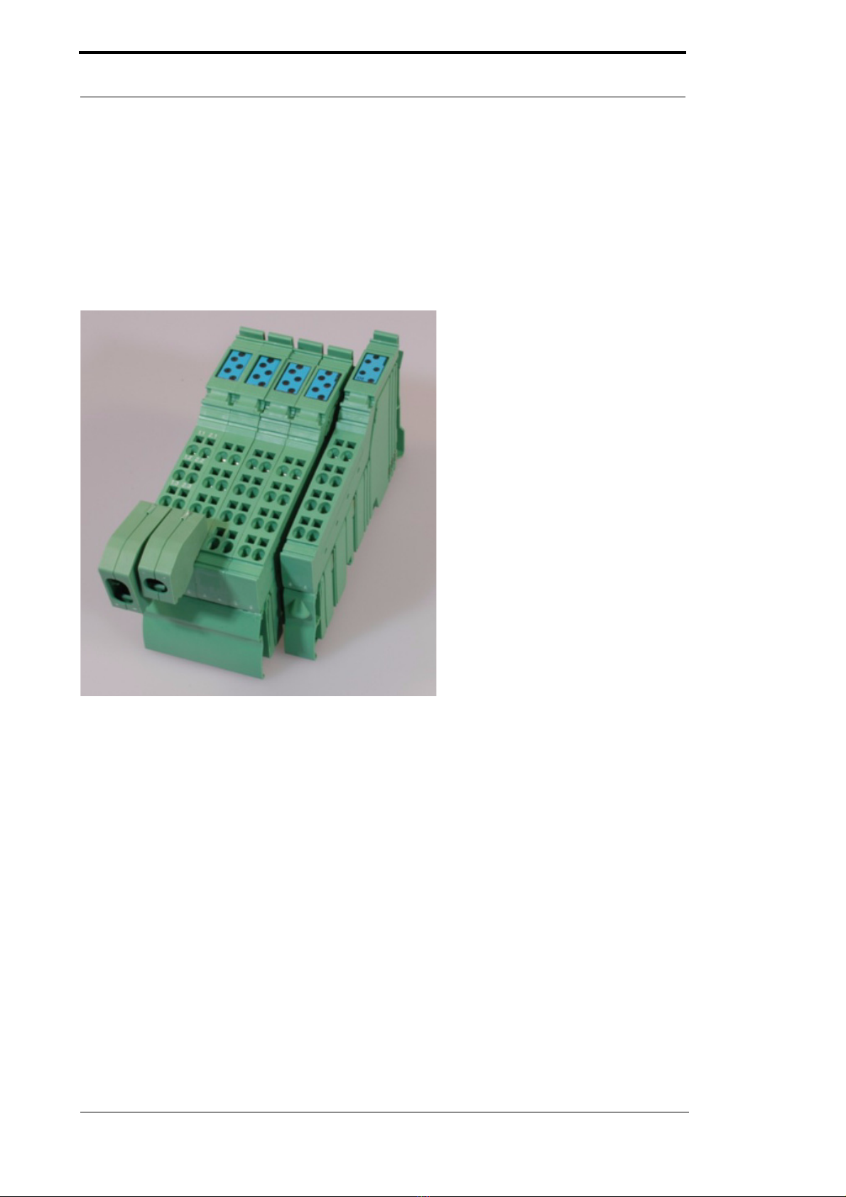
3 Basic unit LOCON 200
LOCON 200 is a modular cam control in industrial design for DIN-rail mounting. The basic device
is made for the connection of an SSI-encoder (Singleturn or Multiturn), 13 bit parallel or for an
incremental encoder for a counting area of up to 16 mio.
The cam control that can be configured by the customer as desired features 16 I/Os that can be
used any way as inputs or outputs. Optionally LOCON 200 is also available with a PROFIBUS-
interface. Additionally extension modules with 8 I/Os can be ordered.
13.11.18 Instruction manual LOCON 200 V. 4.6 13
Deutschmann Automation GmbH & Co. KG Mechanical installation instructions
4 Mechanical installation instructions
4.1 Installation
LOCON 200 is a modular cam control in industrial design for DIN-rail mounting.
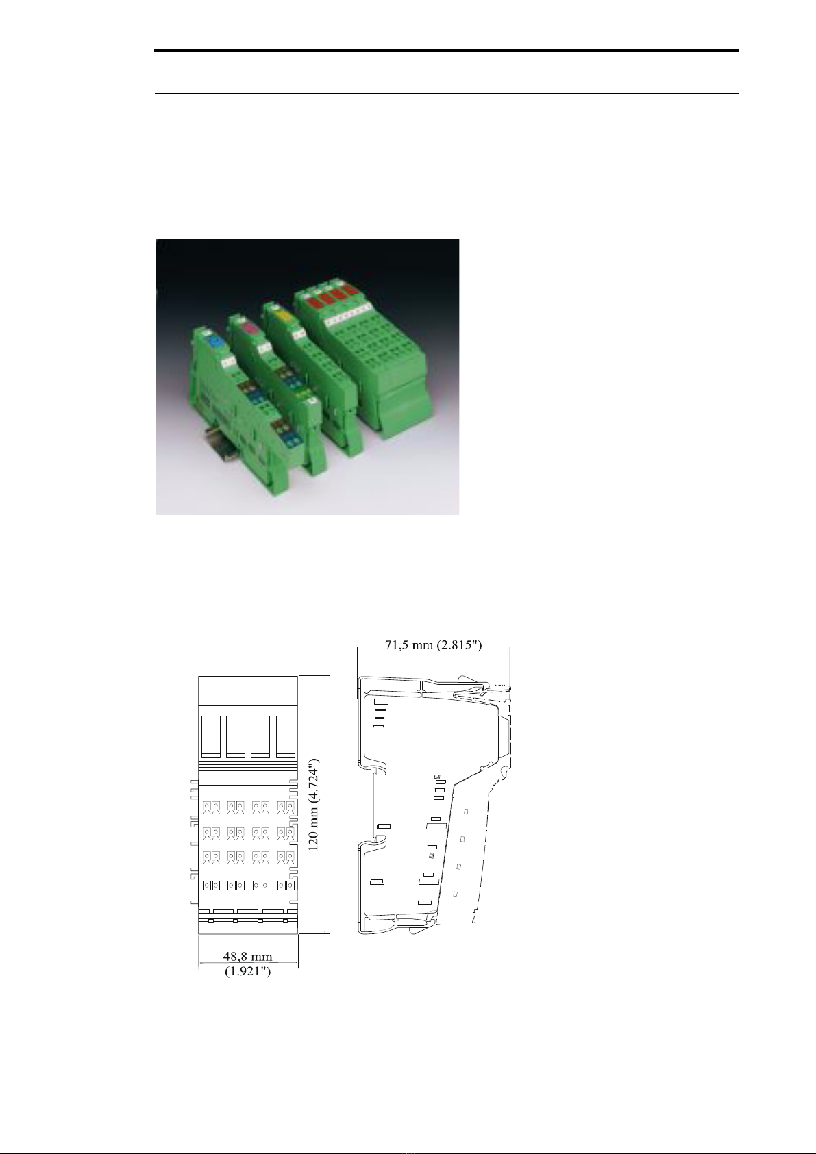
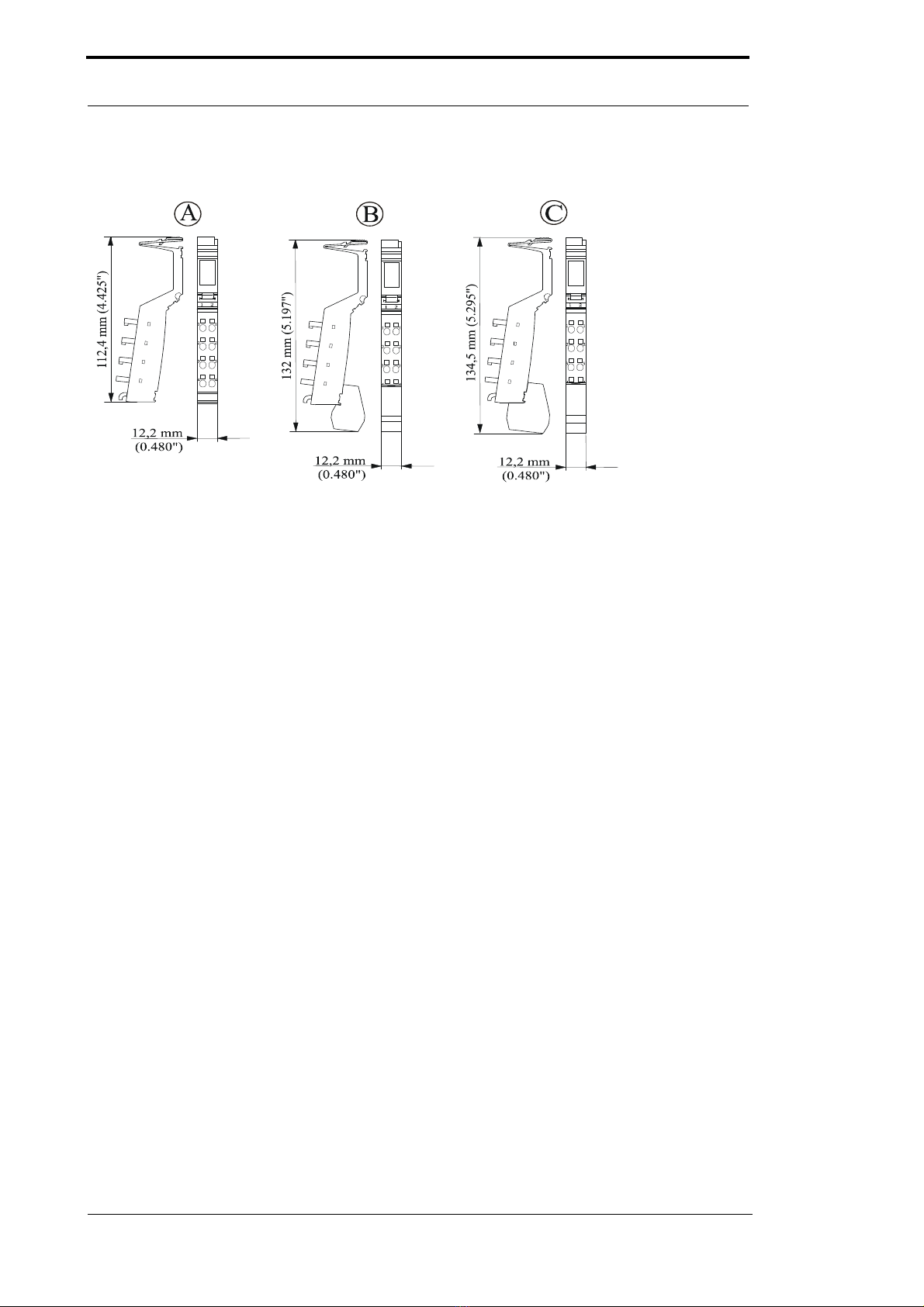
4.2 Housing dimension
The housing dimension of LOCON 200 results from the dimension of the basic unit and the
dimensions of the connectors.
Housing
Mechanical installation instructions Deutschmann Automation GmbH & Co. KG
14 Instruction manual LOCON 200 V. 4.6 13.11.18
Connectors
4.3 Mounting / dismounting of the extension module
The extension module is exclusively meant for the use at a LOCON 200.
It is simply attached to the LOCON 200: No further tool is required to do so. By sequencing the
potential and the bussignal connection between the components is automatically built up.
A later exchange is possible by pulling out or plugging in without any additional tools.
4.4 Connecting lines
Shielded and unshielded lines are used for the device.
For the connection of the encoder or the communication a shielded line is used. The shield is
connected by means of a shield connector, the encoder via the connectors X2 or X3 and X4 and
the communication via the connector X1 in accordance with chapter "Electrical connections
LOCON 200".
Through the tension spring connection points it is possible to connect lines with a diameter of 0.2
mm2 up to 1.5 mm2.
Caption:
A Standard connector
B Shield connector
C Bisignal connector
The depth of the connector is irrelevant since it does not affect the depth of the total housing.

13.11.18 Instruction manual LOCON 200 V. 4.6 15
Deutschmann Automation GmbH & Co. KG Mechanical installation instructions
4.4.1 Connecting lines without shield
Connection example connector

Mechanical installation instructions Deutschmann Automation GmbH & Co. KG
16 Instruction manual LOCON 200 V. 4.6 13.11.18
4.4.2 Connecting shielded lines
E

13.11.18 Instruction manual LOCON 200 V. 4.6 17
Deutschmann Automation GmbH & Co. KG Mechanical installation instructions
4.4.3 Grounding clip
The grounding clip in the cable screen can be used in accordance to the line cross section:
When using thin lines then the curvature of the grounding clip has to be directed towards the line
(see pictures D - F), for thicker lines the other way round (see pictures A - C).
Electrical connections LOCON 200 Deutschmann Automation GmbH & Co. KG
18 Instruction manual LOCON 200 V. 4.6 13.11.18
5 Electrical connections LOCON 200
5.1 Front view LOCON 200
5.2 Assignment X1 (communication)
Pin RS232 DICNET (RS485) PROFIBUS (optionally)
1.1 / 2.1 +24V Gnd +24V Gnd +24V Gnd
1.2 / 2.2 n. c. n. c. n. c. n. c. PB+ PB-
1.3 / 2.3 TxD RxD DIC+ DIC- TxD RxD
1.4 / 2.4 PE PE PE PE PE PE
Pin Modbus RS485 (optional) Modbus RS485 (optional) Modbus RS232 (optional)
1.1 / 2.1 +24V Gnd +24V Gnd +24V Gnd
1.2 / 2.2 n. c. n. c. n. c. n. c. n. c. n. c.
1.3 / 2.3 485+ 485- TxD RxD TxD RxD
1.4 / 2.4 PE PE PE PE PE PE

13.11.18 Instruction manual LOCON 200 V. 4.6 19
Deutschmann Automation GmbH & Co. KG Electrical connections LOCON 200
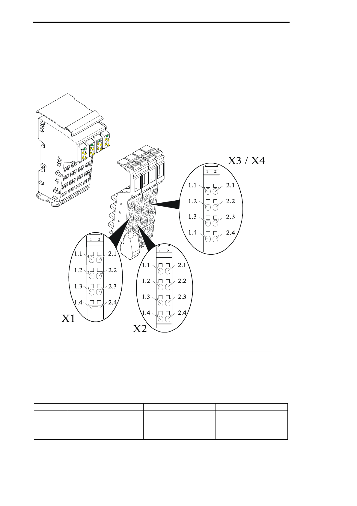
5.3 Assignment X2 (encoder connection SSI + incremental)
5.4 Assignment X3 + X4 (I/Os)
X3 + X4 consist of 16 I/Os that can be configured any way as inputs or outputs including various
signals, such as Preset, Out-Enable, external program selection and so on. Further information
can be found in the chapter "Signal description LOCON 200". There are exceptions when it
comes to a connection of a parallel absolute encoder or an incremental encoder with 24V-signals
(see below).
5.4.1 Assignment X3 + X4 basic device
5.4.2 Assignment X3 + X4 for the connection of a parallel absolute encoder
A parallel encoder is always connected „from the front“. That means the
encoder’s track 1 is always located on the l/O 1. If, for instance, an
encoder with a resolution of 360 is connected, only 9 tracks are required.
That way the tracks 10, 11, 12 and 13 are then available again as I/Os 10,
11, 12 and 13.
5.4.3 Assignment X3 + X4 for the connection of an incremental encoder 24V
5.4.4 Assignment X2 - X4 for the connection of counting/direction inputs
Pin SSI Ink 422
1.1 / 2.1 +24V_Enc. Gnd_Enc. +24V_Enc. Gnd_Enc.
1.2 / 2.2 Clk+ Clk- A+ A-
1.3 / 2.3 Dat+ Dat- B+ B-
1.4 / 2.4 PE PE PE PE
Pin X3 X4
1.1 / 2.1 I/O 1 I/O 2 I/O 9 I/O 10
1.2 / 2.2 I/O 3 I/O 4 I/O 11 I/O 12
1.3 / 2.3 I/O 5 I/O 6 I/O 13 I/O 14
1.4 / 2.4 I/O 7 I/O 8 I/O 15 I/O 16
Pin X3 X4
1.1 / 2.1 Track 1 Track 2 Track 9 Track 10
1.2 / 2.2 Track 3 Track 4 Track 11 Track 12
1.3 / 2.3 Track 5 Track 6 Track 13 I/O 14
1.4 / 2.4 Track 7 Track 8 I/O 15 I/O 16
Pin X3 X4
1.1 / 2.1 Track A Track B I/O 9 I/O 10
1.2 / 2.2 I/O 3 I/O 4 I/O 11 I/O 12
1.3 / 2.3 I/O 5 I/O 6 I/O 13 I/O 14
1.4 / 2.4 I/O 7 I/O 8 I/O 15 I/O 16
Pin X2 X3 X4
1.1 / 2.1 +24V Gnd Counting input Direction input I/O 9 I/O 10
1.2 / 2.2 Clk+ Clk- I/O 3 I/O 4 I/O 11 I/O 12
1.3 / 2.3 Dat+ Dat- I/O 5 I/O 6 I/O 13 I/O 14
1.4 / 2.4 PE PE I/O 7 I/O 8 I/O 15 I/O 16

Electrical connections LOCON 200 Deutschmann Automation GmbH & Co. KG
20 Instruction manual LOCON 200 V. 4.6 13.11.18
The counting input and direction input are always steadily assigned to
the I/Os 1 or 2 and cannot be assigned as desired..
5.4.5 Assignment extension module I/O 8
Each extension module I/O 8 features 8 I/Os that are consecutively numbered, starting from the
basis.
It results in the following assignment on the 1. extension module:
The outputs are located on the front connector pins, followed by the inputs. If, for instance, on the
first extension module I/O 8 (on the right side, seen from the base unit) the number of outputs is
configured to 6, then the arrangement of inputs or outputs looks as follows:
Pin X1
1.1 / 2.1 I/O 17 I/O 18
1.2 / 2.2 I/O 19 I/O 20
1.3 / 2.3 I/O 21 I/O 22
1.4 / 2.4 I/O 23 I/O 24
Pin X1
1.1 / 2.1 O 17 O 18
1.2 / 2.2 O 19 O 20
1.3 / 2.3 O 21 O 22
1.4 / 2.4 I 23 I 24
Other manuals for LOCON 200
1
This manual suits for next models
1
Table of contents
Popular Control Unit manuals by other brands

Raytheon Anschütz
Raytheon Anschütz Standard 22 GYRO COMPASS Operator's and service manual

Goetze
Goetze 2140 Assembly and maintenance instructions

Behringer
Behringer 2500 Series quick start guide

Vetus
Vetus VRF56 installation instructions

Compur Monitors
Compur Monitors Statox 503 manual

National Instruments
National Instruments PXIe-5698 Getting started guide


