DEUTSCHMANN AUTOMATION LOCON 7 User manual

Instruction manual
Electronic cam control
LOCON 7 / LOCON 9
AUDIN Composants & systèmes d'automatisme
Siège :7 bis rue de Tinqueux - 51100 Reims - France -Tel : 03.26.04.20.21 -Fax : 03.26.04.28.20
Agence Nord : 66 rue J.Baptiste Lebas -59910 Bondues -France Tel : 03.20.27.99.84 - Fax : 03.20.27.99.85


24.5.04 Instruction manual LOCON 7, LOCON 9 V. 10.4 3
Deutschmann Automation GmbH & Co. KG
Foreword
This operating manual provides users and OEM customers with all the information necessary for
the installation and operation of the product described in this manual.
All details contained in this manual have been checked carefully, however, they do not represent
an assurance of product characteristics. No liability can be accepted for errors. DEUTSCHMANN
AUTOMATION reserves the right to carry out alterations to the described products in order to
improve the reliability, function or design thereof. DEUTSCHMANN AUTOMATION only accepts
liability to the extent as described in the terms and conditions of sale and delivery.
All rights reserved, including translation. No part of this manual may be reproduced or proces-
sed, copied or distributed in any form whatsoever (print, copy, microfilm or any other process)
without written permission from DEUTSCHMANN AUTOMATION.
Bad Camberg, May 2004
Version 10.4 dated 24.5.04, Art.-No. V3163E
Copyright by DEUTSCHMANN AUTOMATION, D-65520 Bad Camberg 1994-2004

Deutschmann Automation GmbH & Co. KG
4 Instruction manual LOCON 7, LOCON 9 V. 10.4 24.5.04

24.5.04 Instruction manual LOCON 7, LOCON 9 V. 10.4 5
Deutschmann Automation GmbH & Co. KG
1 Introduction . . . . . . . . . . . . . . . . . . . . . . . . . . . . . . . . 9
1.1 On this manual . . . . . . . . . . . . . . . . . . . . . . . . . . . . . . . 9
1.1.1 Symbols . . . . . . . . . . . . . . . . . . . . . . . . . . . . . . . . . . . 9
1.1.2 Concepts . . . . . . . . . . . . . . . . . . . . . . . . . . . . . . . . . . . 9
1.1.3 Suggestions . . . . . . . . . . . . . . . . . . . . . . . . . . . . . . . . . 9
1.2 From the mechanical system to an electronic system . . . . . . . . . . 10
1.3 Deutschmann Automation’s range of products . . . . . . . . . . . . . . 10
2 EMC Directives for products of Deutschmann Automation . . . . . .11
3 Cam control LOCON 7 and LOCON 9 . . . . . . . . . . . . . . . . . 12
3.1 Structure of the unit . . . . . . . . . . . . . . . . . . . . . . . . . . . . 12
3.2 Pin assignment LOCON 7 and LOCON 9 . . . . . . . . . . . . . . . . . 12
3.3 Display elements LOCON 7 and LOCON 9 . . . . . . . . . . . . . . . . 13
3.4 Mechanical installation . . . . . . . . . . . . . . . . . . . . . . . . . . 13
3.5 Electrical installation . . . . . . . . . . . . . . . . . . . . . . . . . . . 13
3.5.1 Connecting the supply voltage . . . . . . . . . . . . . . . . . . . . . . . .13
3.5.2 Connecting inputs and outputs . . . . . . . . . . . . . . . . . . . . . . . .13
3.5.3 Connecting the external program selection . . . . . . . . . . . . . . . . .13
3.5.4 Connecting the serial RS232-interface . . . . . . . . . . . . . . . . . . . .14
4 Networking terminals with cam controls and PCs . . . . . . . . . . 15
4.1 RS232 link . . . . . . . . . . . . . . . . . . . . . . . . . . . . . . . . . 15
4.2 RS485-connection (DICNET®) - LOCON 9 only . . . . . . . . . . . . . 15
4.3 Cable type for DICNET® . . . . . . . . . . . . . . . . . . . . . . . . . 15
4.3.1 Earthing, shielding . . . . . . . . . . . . . . . . . . . . . . . . . . . . . .16
4.3.2 Line termination at DICNET® . . . . . . . . . . . . . . . . . . . . . . . .16
4.4 Comparison DICNET® - RS232 . . . . . . . . . . . . . . . . . . . . . 16
4.5 Connection examples . . . . . . . . . . . . . . . . . . . . . . . . . . . 17
4.5.1 DICNET link LOCON - TERM . . . . . . . . . . . . . . . . . . . . . . . .17
4.5.2 RS232 link LOCON - TERM . . . . . . . . . . . . . . . . . . . . . . . . .18
4.5.3 DICNET link LOCON - TERM - PC . . . . . . . . . . . . . . . . . . . . .19
4.5.4 Connecting the encoder . . . . . . . . . . . . . . . . . . . . . . . . . . .20
4.5.4.1 SSI-absolute encoder . . . . . . . . . . . . . . . . . . . . . . . . . . . . 20
4.5.4.2 Incremental encoder (A/B-tracks shifted by 90°) . . . . . . . . . . . . . . 20
4.5.4.3 Count-/direction signals . . . . . . . . . . . . . . . . . . . . . . . . . . . 20
5 External operating unit TERM 5 . . . . . . . . . . . . . . . . . . . . 21
5.1 Structure of the device . . . . . . . . . . . . . . . . . . . . . . . . . . 21
5.2 View TERM 5/6 . . . . . . . . . . . . . . . . . . . . . . . . . . . . . . 21
5.3 Technical dimensional drawings . . . . . . . . . . . . . . . . . . . . . 22
5.3.1 TERM 5 / TERM 6 . . . . . . . . . . . . . . . . . . . . . . . . . . . . . .22
5.3.2 TERM 5-H / TERM 6-H . . . . . . . . . . . . . . . . . . . . . . . . . . . .23
5.3.3 TERM 5-T / TERM 6-T . . . . . . . . . . . . . . . . . . . . . . . . . . . .24
5.4 Pin assignment TERM 5/6 . . . . . . . . . . . . . . . . . . . . . . . . 25
5.5 Display element TERM 5 . . . . . . . . . . . . . . . . . . . . . . . . . 25

Deutschmann Automation GmbH & Co. KG
6 Instruction manual LOCON 7, LOCON 9 V. 10.4 24.5.04
6 External display unit TERM 4 . . . . . . . . . . . . . . . . . . . . . . 26
6.1 Assembly of the unit . . . . . . . . . . . . . . . . . . . . . . . . . . . 26
6.2 Dimensional drawing TERM 4 . . . . . . . . . . . . . . . . . . . . . . 26
6.3 Technical dimensional drawing . . . . . . . . . . . . . . . . . . . . . . 27
6.3.1 TERM 4 . . . . . . . . . . . . . . . . . . . . . . . . . . . . . . . . . . . 27
6.4 Pin assignment TERM 4 . . . . . . . . . . . . . . . . . . . . . . . . . 27
7 Programming LOCON 7 and LOCON 9 . . . . . . . . . . . . . . . . . 28
7.1 Basics . . . . . . . . . . . . . . . . . . . . . . . . . . . . . . . . . . . 28
7.1.1 Backup on PC . . . . . . . . . . . . . . . . . . . . . . . . . . . . . . . . 28
7.2 Program structure . . . . . . . . . . . . . . . . . . . . . . . . . . . . . 28
7.3 Definitions . . . . . . . . . . . . . . . . . . . . . . . . . . . . . . . . . 30
7.4 Zero offset . . . . . . . . . . . . . . . . . . . . . . . . . . . . . . . . . 31
7.4.1 Reading out the actual zero offset . . . . . . . . . . . . . . . . . . . . . 31
7.4.2 Programming the zero offset . . . . . . . . . . . . . . . . . . . . . . . . 31
7.5 Displaying the active program . . . . . . . . . . . . . . . . . . . . . . 31
7.6 Changing the active program . . . . . . . . . . . . . . . . . . . . . . . 32
7.6.1 External program selection via plug connector . . . . . . . . . . . . . . . 32
7.7 Selecting the output number . . . . . . . . . . . . . . . . . . . . . . . 32
7.8 Displaying existing cams . . . . . . . . . . . . . . . . . . . . . . . . . 32
7.9 Changing existing cams . . . . . . . . . . . . . . . . . . . . . . . . . . 33
7.10 Deleting existing cams . . . . . . . . . . . . . . . . . . . . . . . . . . 33
7.11 New programming of cams . . . . . . . . . . . . . . . . . . . . . . . . 33
7.12 Teach-in programming . . . . . . . . . . . . . . . . . . . . . . . . . . 34
7.13 Shifting all cams on one output . . . . . . . . . . . . . . . . . . . . . . 34
7.14 Idle time compensation (LOCON 9 only) . . . . . . . . . . . . . . . . . 34
7.14.1 Program-dependent idle times . . . . . . . . . . . . . . . . . . . . . . . 35
7.14.2 Programming or changing idle times . . . . . . . . . . . . . . . . . . . . 35
7.15 Clear all . . . . . . . . . . . . . . . . . . . . . . . . . . . . . . . . . . 35
7.16 Inverting the rotational direction of the absolute encoder . . . . . . . . . 35
8 Initialization of encoder resolution, counting area, DICNET-ID . . . . 37
8.1 Parameter’s set in factory . . . . . . . . . . . . . . . . . . . . . . . . . 37
8.2 Initialization via TERM 24 . . . . . . . . . . . . . . . . . . . . . . . . . 37
8.3 Initialization via TERM 32 . . . . . . . . . . . . . . . . . . . . . . . . . 37
8.4 Initialization via PC . . . . . . . . . . . . . . . . . . . . . . . . . . . . 37
9 Commissioning . . . . . . . . . . . . . . . . . . . . . . . . . . . . . 38
9.1 Self-test . . . . . . . . . . . . . . . . . . . . . . . . . . . . . . . . . . 38
10 Technical data . . . . . . . . . . . . . . . . . . . . . . . . . . . . . . 39
10.1 Technical data LOCON 7 . . . . . . . . . . . . . . . . . . . . . . . . . 39
10.2 Technische Daten LOCON 9 . . . . . . . . . . . . . . . . . . . . . . . 40
10.3 Technical data TERM 4 . . . . . . . . . . . . . . . . . . . . . . . . . . 41

24.5.04 Instruction manual LOCON 7, LOCON 9 V. 10.4 7
Deutschmann Automation GmbH & Co. KG
10.4 Technical data TERM 5/6 . . . . . . . . . . . . . . . . . . . . . . . . . 42
10.5 Specification of the input levels . . . . . . . . . . . . . . . . . . . . . . 42
10.6 Conversion formula rev/min <--> Cycle time . . . . . . . . . . . . . . . 42
11 Error messages . . . . . . . . . . . . . . . . . . . . . . . . . . . . . 43
11.1 Error number 1..19 (irrecoverable error) . . . . . . . . . . . . . . . . . 43
11.2 Error number 20..99 (warning) . . . . . . . . . . . . . . . . . . . . . . 43
11.3 Error number 100..199 (serious error) . . . . . . . . . . . . . . . . . . 45
11.4 Error number 200-299 . . . . . . . . . . . . . . . . . . . . . . . . . . . 46
12 Communication interface . . . . . . . . . . . . . . . . . . . . . . . . 47
13 Servicing . . . . . . . . . . . . . . . . . . . . . . . . . . . . . . . . . 48
13.1 Returning a unit . . . . . . . . . . . . . . . . . . . . . . . . . . . . . . 48
13.2 Internet . . . . . . . . . . . . . . . . . . . . . . . . . . . . . . . . . . 48
14 Appendix . . . . . . . . . . . . . . . . . . . . . . . . . . . . . . . . 49
14.1 Description and connection of the DICNET®-Adapter . . . . . . . . . . 49
14.1.1 DICNET®-Adapter DICADAP 3 . . . . . . . . . . . . . . . . . . . . . . .49

Deutschmann Automation GmbH & Co. KG
8 Instruction manual LOCON 7, LOCON 9 V. 10.4 24.5.04

24.5.04 Instruction manual LOCON 7, LOCON 9 V. 10.4 9
Deutschmann Automation GmbH & Co. KG Introduction
1 Introduction
1.1 On this manual
This manual documents installation, functions and operation of the Deutschmann unit specified
on the cover sheet and in the header.
1.1.1 Symbols
Particularly important text sections can be seen from the adjacent pictogram.
You should always follow this information since, otherwise, this could result in mal-
functions or operating errors.
1.1.2 Concepts
The expressions ‘LOCON’ and ’TERM’ are frequently used throughout this manual with no fur-
ther model specifications. In such cases, the information applies to the entire model series.
1.1.3 Suggestions
We are always pleased to receive suggestions and wishes etc. and endeavour to allow for these.
It is also helpful if you bring our attention to any errors.

Introduction Deutschmann Automation GmbH & Co. KG
10 Instruction manual LOCON 7, LOCON 9 V. 10.4 24.5.04
1.2 From the mechanical system to an electronic system
The purpose of electronic programming limit switches is not only to take the place of mechanical
controllers but to render their function more precise and simpler, to provide a universal range of
application and to reduce wear.
The mechanical cam control actuates a switch over sections of a circle, and this switch is closed
over the length of this section. Such a section is defined as a "cam".
Each switch represents one output. Several circuits arranged in parallel produce the number of
outputs.
Picture 1: Mechanical cam control
This basic principle has been adopted from the mechanical cam controls. A cam is programmed
for an output by entering a switch-on point and a switch-off point. The output is switched on
between these points.
Thanks to twenty years of experience, consistent further development and the use of ultra-mod-
ern technology, DEUTSCHMANN AUTOMATION has now become one of the leading suppliers
of electronic cam controls.
1.3 Deutschmann Automation’s range of products
See our homepage at http://www.deutschmann.de.

24.5.04 Instruction manual LOCON 7, LOCON 9 V. 10.4 11
Deutschmann Automation GmbH & Co. KG EMC Directives for products of Deutschmann Automation
2 EMC Directives for products of Deutschmann Automation
The installation of our products has to be carried out considering the relevant EMC directives as
well as our internal instructions.
For more information see ’EMC Directives’ on our homepage at http://www.deutschmann.de.

Cam control LOCON 7 and LOCON 9 Deutschmann Automation GmbH & Co. KG
12 Instruction manual LOCON 7, LOCON 9 V. 10.4 24.5.04
3 Cam control LOCON 7 and LOCON 9
3.1 Structure of the unit
According to the picture below, the complete device is stored in a plastic housing for DIN-rail
mounting (79x96x25 WxHxD):
3.2 Pin assignment LOCON 7 and LOCON 9
18 pol. screw-plug connector with the following assignment:
The power consumption at +24V is max. 100mA without load. The power that is required as load
on the output 1 to output 8 (max. 1A), must additionally be available over +24V.
Pin-No. Connection SSI-encoder Connection incremental encoder Count-/direction signals
1 SSIDAT+ SelectNumber SelectCount
2 SSIDAT- Clear+ Clear+
3 SSICLK- Inc-track B Down
4 SSICLK+ Inc-track A Count
5 Prog-No. 1
6 Prog-No. 2 Clear Enable+ (X42 only)
7 Output 1
8 Output 2
9 Output 3
10 Output 4
11 Output 5
12 Output 6
13 Output 7
14 Output 8
15 Tx-LOCON / DICNET+
16 Rx-LOCON / DICNET-
17 GND
18 +24V

24.5.04 Instruction manual LOCON 7, LOCON 9 V. 10.4 13
Deutschmann Automation GmbH & Co. KG Cam control LOCON 7 and LOCON 9
3.3 Display elements LOCON 7 and LOCON 9
LED 1 (yellow) Program-No. 1 active
LED 2 (yellow) Program-No 2 active
LED 3 (green) SSI-Interface ok
LED 4 (red) Error-LED
LED 5 (green) Output 1 active
LED 6 (green) Output 2 active
LED 7 (green) Output 3 active
LED 8 (green) Output 4 active
LED 9 (green) Output 5 active
LED 10 (green) Output 6 active
LED 11 (green) Output 7 active
LED 12 (green) Output 8 active
3.4 Mechanical installation
LOCON 7 and LOCON 9 are designed for DIN-rail mounting .
3.5 Electrical installation
The complete electrical wiring of the basic device LOCON is carried out via the 18 pol. screw-
plug-connection on the front side.
3.5.1 Connecting the supply voltage
The supply voltage is 18..28V DC (typ. 24V DC) and is wired according to chapter "Connection
elements".
Before switching on the supply voltage the corresponding inputs and outputs have to be wired, to
avoid malfunctions.
3.5.2 Connecting inputs and outputs
As signal encoder of the machine SSI-, pulse- or incremental-encoders are used. They are con-
nected to the pins 1 - 4 (see pin assignment).
The output pins 7 - 14 of LOCON 7/9 are plus-switching 24V; that means an active output has a
level of 24V compared with GND, a deleted output is high-ohmic.
The outputs are short-circuit-proof and can drive max. 300mA, at which point the 8 outputs may
only be loaded with max. 1A.
In case of a permanent short-circuit or an overload the corresponding outputs are switched off,
the error-LED flashes, and a corresponding error message is shown on a connected display.
3.5.3 Connecting the external program selection
The pins "Program selection 1" and "Program selection 2" have to be wired only, in case the
external program switch (e. g. via PLC) shall be made. Please note that a program shift is carried
out with every change on the input pins; that means, if a program is chosen via the plugs, the sig-
nals "Program-selection 1" and "Program-selection 2" must be held on the respective level, until
a new program selection shall be made.
The following assignment applies: Prog.-selection 2 Prog.-selection 1 Program
00 0
024V1
24V 0 2
24V 24V 3

Cam control LOCON 7 and LOCON 9 Deutschmann Automation GmbH & Co. KG
14 Instruction manual LOCON 7, LOCON 9 V. 10.4 24.5.04
3.5.4 Connecting the serial RS232-interface
For connecting a serial RS232-interface to a PC a mass-produced cable (9 pol. D-SUB plug on
one end and an open cable end on the other end) can be ordered from Deutschmann Automa-
tion.
The following assignment applies: white = Tx-LOCON7
green = Rx-LOCON7
brown= GND
Please note that at the RS232-interface the Tx-wire of one participant is con-
nected with the Rx-wire of the other participant and vice versa.

24.5.04 Instruction manual LOCON 7, LOCON 9 V. 10.4 15
Deutschmann Automation GmbH & Co. KG Networking terminals with cam controls and PCs
4 Networking terminals with cam controls and PCs
The chapters below illustrate certain connection examples between the units and a PC, via the
DICNET bus as well as via the RS232 interface.
All DEUTSCHMANN controls (LOCON, ROTARNOCK ...) with a DICNET bus can be included in
this network. The following principles apply in general:
4.1 RS232 link
An RS232 link is always a point-to-point link for 2 users.
Here, it must be borne in mind that, on connection, the Tx end of one user is connected to the Rx
end of the other user and vice versa. Moreover, the device ground potentials must be intercon-
nected.
4.2 RS485-connection (DICNET®) - LOCON 9 only
A DICNET link is a bus system to which at maximum configuration level 16 cam controls
(LOCON 32, LOCON 9 ...), 16 display units (TERM 4), 3 operating terminals (TERM 6, TERM 24
...) and 1 PC can be connected simultaneously via a twisted two-wire line which should be
shielded.
All "DICNET+“ ports are interconnected and all "DICNET-" ports are interconnected. A wiring as
on the RS232 interface is not made.
Likewise, a connection of the individual device ground potentials as on the RS232 interface has
not necessarily to be made; however, you must ensure that the potential difference between
the individual devices does not exceed 7 V.
Consequently, equipotential bonding is generally carried out in practice at a central point (for
example, in the switch cabinet).
Moreover, please ensure that the two bus users feature bus termination resistors at the
start and end of the bus by connecting DICNET+ to R+ and DICNET- to R-, since, otherwise,
serious transmission problems could occur.
If the devices are connected to the bus with a stub-end feeder, the length of the stub-end feeder
may not exceed 1 m, so as to guarantee trouble-free operation.
By default LOCON 9 is supplied with activated bus termination resistor.
4.3 Cable type for DICNET®
A shielded, twisted, 2-core cable (twisted pair) is recommended to be used as bus cable. The
shield serves to enhance electromagnetic compatibility (EMC). However, an unshielded cable
may also be used if ambient conditions permit it, i. e. if no electromagnetic interference (EMI) is
to be expected.
The characteristic impedance of the cable should be between 100 and 130 *Ω at f > 100 kHz; the
cable capacitance should be < 60 pF/m wherever possible and the wire cross-section should be
minimum 0.22 mm2(24 AWG).
A cable that fully complies with these specifications and that has been developed specifically for
use in field bus systems is the UNITRONIC®-BUS LD cable 2 x 2 x 0.22, available on a drum
from LAPP KABEL in Stuttgart, or by the meter from Deutschmann Automation.

Networking terminals with cam controls and PCs Deutschmann Automation GmbH & Co. KG
16 Instruction manual LOCON 7, LOCON 9 V. 10.4 24.5.04
The minimum wiring with shielding between two bus users is shown in the following illustration:
Picture 2: DICNET-wiring
The two signal wires may not be reversed!
GND of the two devices do not necessarily have to be connected.
The potential difference between the data reference potentials GND of all
interface connections may not exceed ± 7 V.
4.3.1 Earthing, shielding
If using a shielded bus cable, we recommend that the shield is connected at both ends and with
low inductance with the protective ground in order to achieve optimum EMC wherever possible.
4.3.2 Line termination at DICNET®
The two ends of the entire bus cable must each be fitted with a line termination. This avoids sig-
nal reflections on the line and ensures a defined open-circuit potential if no user is transmitting
(state of rest between the telegrams, so-called idle state).
In this case, please ensure that the line termination is made at the physical ends of the bus
cable, i. e. the integrated bus termination resistor must be activated at both devices located at
the start and end of the bus.
4.4 Comparison DICNET®- RS232
If you intend to set up a permanent link between terminal and one or more cam controls, prefer-
ence should be given to connection via the DICNET bus and not the RS232 interface since the
bus features a higher level of data integrity, i. e. transmission errors which may occur, for
instance, as the result of noise pulses are automatically detected and corrected by DICNET up to
a certain extent.
Wherever possible, the RS232 interface should be used only for temporary connections (e. g. for
connecting a PC).

24.5.04 Instruction manual LOCON 7, LOCON 9 V. 10.4 17
Deutschmann Automation GmbH & Co. KG Networking terminals with cam controls and PCs
4.5 Connection examples
4.5.1 DICNET link LOCON - TERM
LOCON and TERM are connected as follows via DICNET:
Picture 3: DICNET link terminal - LOCON
The presented devices exemplary stand for Deutschmann terminals and cam
controls of the series LOCON / ROTARNOCK respectively.
The two ground potentials do not have to be interconnected. However, you must ensure that the
GND potential between the individual DICNET bus users does not differ by more than 7 V. Other-
wise, equipotential bonding must be used.
The bus termination resistor must be activated on both units.
Consequently, in the case of simple wiring with a LOCON and an external operator control panel,
it is the obvious choice to use the same 24 V supply for both units.

Networking terminals with cam controls and PCs Deutschmann Automation GmbH & Co. KG
18 Instruction manual LOCON 7, LOCON 9 V. 10.4 24.5.04
4.5.2 RS232 link LOCON - TERM
On the RS232 version, only a point-to-point connection between LOCON and the external opera-
tor control panel is possible.
In this case, the Tx LOCON line must be connected to the Rx TERM line of the operator control
unit and vice versa, as can be seen from the illustration below.
The two ground potentials must be connected.
Picture 4: RS232 link Terminal - LOCON
The presented devices exemplary stand for Deutschmann terminals and cam
controls of the series LOCON / ROTARNOCK respectively.

24.5.04 Instruction manual LOCON 7, LOCON 9 V. 10.4 19
Deutschmann Automation GmbH & Co. KG Networking terminals with cam controls and PCs
4.5.3 DICNET link LOCON - TERM - PC
A PC can be integrated in a DICNET®bus system using a DICNET adapter. The connection to
the PC is made at a serial port COMx - see the illustration below.
Picture 5: Link DICNET bus to PC
The presented devices exemplary stand for Deutschmann terminals and cam
controls of the series LOCON / ROTARNOCK respectively.

Networking terminals with cam controls and PCs Deutschmann Automation GmbH & Co. KG
20 Instruction manual LOCON 7, LOCON 9 V. 10.4 24.5.04
4.5.4 Connecting the encoder
4.5.4.1 SSI-absolute encoder
If LOCON 7/9 is operated with a SSI-encoder, then the 4 data- and clock-lines of the SSI encoder
are applied to the pins 1 - 4 of the LOCON 7/9 according to chapter "Pin assignment LOCON 7
and LOCON 9".
4.5.4.2 Incremental encoder (A/B-tracks shifted by 90°)
LOCON 7/9 can be operated by an incremental encoder with any resolution, at which point the
limiting values stated in the technical data, have to be kept.
24-Volt-incremental encoders are supported with two tracks A and B (optionally with zero pulse)
shifted by 90°-degree centigrade, that according to the chapter connection elements are wired
(INK_GEBER_A, INK_GEBER_B) .
With the input "CLEAR+" the count of the LOCON 7/9 can be deleted, where at LOCON 7 you
have to pay attention, that the pulse width of the clear-signals is at least 1ms, at LOCON 9 an
pulse width of 1µs is enough.
The input "SelectCount" remains not connected, or is connected with GND.
4.5.4.3 Count-/direction signals
Shall LOCON 7/9 work as incremental cam control with count- and direction signals, this mode
can be adjusted by means of the input "SelectCount" by connecting with 24V.
With each increasing flank it is counted further to one worth at the input "Count^", where the input
"Down" defines the count direction. If this input is not connected, or put to GND it is counted
upwards (+1), at a connection of "Down" with 24V it is counted downwards (-1).
With the input "CLEAR+" the count of LOCON 7/9 can be deleted, where you have to pay atten-
tion, that the pulse width of the clear-signals is at least 1ms (at LOCON 7) or 1µs (at LOCON 9).
With this mode it is possible to construct a very low-priced complete solution, since for instance
an initiator or switch can be inserted as pulse encoder.
The count input urgently has to be debounced, as otherwise every bounce
impulse is evaluated as count pulse.
This manual suits for next models
1
Table of contents
Other DEUTSCHMANN AUTOMATION Controllers manuals
Popular Controllers manuals by other brands
ROBO Cylinder
ROBO Cylinder GRSS instruction manual

Rockwell Automation
Rockwell Automation Allen-Bradley Micro800 manual
Mitsubishi
Mitsubishi MELSEC Q Series Reference manual

Emerson
Emerson Leroy Somer R450 Installation and Maintenance

Mitsubishi Electric
Mitsubishi Electric MELSEC-L02SCPU user manual
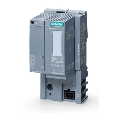
Siemens
Siemens SIMATIC ET 200SP System manual
