DEUTSCHMANN AUTOMATION LOCON 15 Series User manual

Instruction Manual
LOCON 15
TERM 4 / TERM 5 / TERM 6
Deutschmann Automation GmbH & Co. KG
www.deutschmann.com | wiki.deutschmann.de

Manual Art.-No.: V3533E

27.1.20 Instruction manual LOCON 15, TERM 4, 5, 6 V. 1.5 2
Deutschmann Automation GmbH & Co. KG
Foreword
This operating manual provides users and OEM customers with all the information necessary for
the installation and operation of the product described in this manual.
All details contained in this manual have been checked carefully, however, they do not represent
an assurance of product characteristics. No liability can be accepted for errors. DEUTSCHMANN
AUTOMATION reserves the right to carry out alterations to the described products in order to
improve the reliability, function or design thereof. DEUTSCHMANN AUTOMATION only accepts
liability to the extent as described in the terms and conditions of sale and delivery.
All rights reserved, including translation. No part of this manual may be reproduced or proces-
sed, copied or distributed in any form whatsoever (print, copy, microfilm or any other process)
without written permission from DEUTSCHMANN AUTOMATION.
Bad Camberg, January 2020

Deutschmann Automation GmbH & Co. KG
3 Instruction manual LOCON 15, TERM 4, 5, 6 V. 1.5 27.1.20

27.1.20 Instruction manual LOCON 15 TERM 4, 5, 6 V. 1.5 5
Deutschmann Automation GmbH & Co. KG
1 Introduction . . . . . . . . . . . . . . . . . . . . . . . . . . . . . . . . . . . . . . . . . . 9
1.1 On this manual . . . . . . . . . . . . . . . . . . . . . . . . . . . . . . . . . . . . 9
1.1.1 Symbols . . . . . . . . . . . . . . . . . . . . . . . . . . . . . . . . . . . . . . . . 9
1.1.2 Concepts . . . . . . . . . . . . . . . . . . . . . . . . . . . . . . . . . . . . . . . 9
1.1.3 Suggestions . . . . . . . . . . . . . . . . . . . . . . . . . . . . . . . . . . . . . .9
1.2 From the mechanical system to an electronic system . . . . . . . . . . . . . . . 10
1.3 Deutschmann Automation’s range of products . . . . . . . . . . . . . . . . . . . 10
2 EMC Directives for products of Deutschmann Automation . . . . . . . . . . . . 11
3 Basic device LOCON 15 . . . . . . . . . . . . . . . . . . . . . . . . . . . . . . . . . . 12
3.1 Technical dimensional drawings . . . . . . . . . . . . . . . . . . . . . . . . . . 13
3.1.1 LOCON 15 . . . . . . . . . . . . . . . . . . . . . . . . . . . . . . . . . . . . . 13
3.1.2 LOCON 15PM . . . . . . . . . . . . . . . . . . . . . . . . . . . . . . . . . . . . 14
3.2 Pin assignment LOCON 15 . . . . . . . . . . . . . . . . . . . . . . . . . . . . . 15
3.3 Signal description LOCON 15 . . . . . . . . . . . . . . . . . . . . . . . . . . . . 16
4 Options . . . . . . . . . . . . . . . . . . . . . . . . . . . . . . . . . . . . . . . . . . . . 17
4.1 LOCON 15 . . . . . . . . . . . . . . . . . . . . . . . . . . . . . . . . . . . . . . 17
4.1.1 Serial interface . . . . . . . . . . . . . . . . . . . . . . . . . . . . . . . . . . . 17
4.1.2 Storing output names and language (option M) . . . . . . . . . . . . . . . . . . 17
5 Special versions . . . . . . . . . . . . . . . . . . . . . . . . . . . . . . . . . . . . . . . 18
5.1 Connecting the supply voltage . . . . . . . . . . . . . . . . . . . . . . . . . . . 18
5.1.1 Connecting inputs and outputs . . . . . . . . . . . . . . . . . . . . . . . . . . . 18
5.2 Special versions . . . . . . . . . . . . . . . . . . . . . . . . . . . . . . . . . . . 18
6 Basic device TERM 5/6 (external operating unit) . . . . . . . . . . . . . . . . . . . 19
6.1 Assembly of the instrument . . . . . . . . . . . . . . . . . . . . . . . . . . . . . 19
6.2 View TERM 5/6 . . . . . . . . . . . . . . . . . . . . . . . . . . . . . . . . . . . 19
6.3 Technical dimensional drawings . . . . . . . . . . . . . . . . . . . . . . . . . . 20
6.3.1 TERM 5 / TERM 6 . . . . . . . . . . . . . . . . . . . . . . . . . . . . . . . . . 20
6.3.2 TERM 5-H / TERM 6-H . . . . . . . . . . . . . . . . . . . . . . . . . . . . . . . 21
6.3.3 TERM 5-T / TERM 6-T . . . . . . . . . . . . . . . . . . . . . . . . . . . . . . . 22
6.4 Pin assignment TERM 5/6 . . . . . . . . . . . . . . . . . . . . . . . . . . . . . . 23
6.4.1 Interface switch-over . . . . . . . . . . . . . . . . . . . . . . . . . . . . . . . . 23
6.5 Programming of several devices with TERM 5/6 . . . . . . . . . . . . . . . . . . 23
6.5.1 Selecting the device number on TERM 5/6 . . . . . . . . . . . . . . . . . . . . 23
6.6 Display of the executed program via TERM 5/6 . . . . . . . . . . . . . . . . . . 24
6.7 Reading and changing cam control parameters . . . . . . . . . . . . . . . . . . 24
6.7.1 Possible error messages on the configuration . . . . . . . . . . . . . . . . . . . 24
6.8 Different and common characteristics of TERM 5 and TERM 6 . . . . . . . . . . 25
7 Basic instrument TERM 4 (external display unit) . . . . . . . . . . . . . . . . . . . 26
7.1 Assembly of the unit . . . . . . . . . . . . . . . . . . . . . . . . . . . . . . . . . 26
7.2 Dimensional drawing TERM 4 . . . . . . . . . . . . . . . . . . . . . . . . . . . . 26

Deutschmann Automation GmbH & Co. KG
6 Instruction manual LOCON 15, TERM 4, 5, 6 V. 1.5 27.1.20
7.3 Technical dimensional drawing . . . . . . . . . . . . . . . . . . . . . . . . . . . 27
7.3.1 TERM 4 . . . . . . . . . . . . . . . . . . . . . . . . . . . . . . . . . . . . . . . 27
7.4 Pin assignment TERM 4 . . . . . . . . . . . . . . . . . . . . . . . . . . . . . . 28
7.5 Interface switch-over . . . . . . . . . . . . . . . . . . . . . . . . . . . . . . . . 28
8 Networking terminals with cam controls and PCs . . . . . . . . . . . . . . . . . . 29
8.1 RS232 link . . . . . . . . . . . . . . . . . . . . . . . . . . . . . . . . . . . . . . 29
8.2 RS485 link (DICNET) . . . . . . . . . . . . . . . . . . . . . . . . . . . . . . . . 29
8.3 Cable type for DICNET® . . . . . . . . . . . . . . . . . . . . . . . . . . . . . . 29
8.3.1 Earthing, shielding . . . . . . . . . . . . . . . . . . . . . . . . . . . . . . . . . . 30
8.3.2 Line termination at DICNET® . . . . . . . . . . . . . . . . . . . . . . . . . . . . 30
8.4 Comparison DICNET® - RS232 . . . . . . . . . . . . . . . . . . . . . . . . . . 30
8.5 Connection examples . . . . . . . . . . . . . . . . . . . . . . . . . . . . . . . . 31
8.5.1 DICNET link LOCON - TERM . . . . . . . . . . . . . . . . . . . . . . . . . . . 31
8.5.2 RS232 link LOCON - TERM . . . . . . . . . . . . . . . . . . . . . . . . . . . . 32
8.5.3 DICNET link LOCON - TERM - PC . . . . . . . . . . . . . . . . . . . . . . . . . 33
9 Programming LOCON . . . . . . . . . . . . . . . . . . . . . . . . . . . . . . . . . . . 34
9.1 Basics . . . . . . . . . . . . . . . . . . . . . . . . . . . . . . . . . . . . . . . . 34
9.2 View LOCON 15 . . . . . . . . . . . . . . . . . . . . . . . . . . . . . . . . . . 34
9.3 Program structure . . . . . . . . . . . . . . . . . . . . . . . . . . . . . . . . . . 35
9.3.1 Definitions . . . . . . . . . . . . . . . . . . . . . . . . . . . . . . . . . . . . . . 38
9.4 Automatical shifting to the speed display . . . . . . . . . . . . . . . . . . . . . . 38
9.5 Zero offset and clear-shift . . . . . . . . . . . . . . . . . . . . . . . . . . . . . . 38
9.5.1 Reading out the actual zero offset . . . . . . . . . . . . . . . . . . . . . . . . . 38
9.5.2 Programming the zero offset . . . . . . . . . . . . . . . . . . . . . . . . . . . . 39
9.6 Displaying the active program . . . . . . . . . . . . . . . . . . . . . . . . . . . 39
9.7 Changing the active program . . . . . . . . . . . . . . . . . . . . . . . . . . . . 39
9.8 Selecting the output number . . . . . . . . . . . . . . . . . . . . . . . . . . . . 40
9.9 Displaying existing cams . . . . . . . . . . . . . . . . . . . . . . . . . . . . . . 41
9.10 Changing existing cams . . . . . . . . . . . . . . . . . . . . . . . . . . . . . . . 41
9.11 Deleting existing cams . . . . . . . . . . . . . . . . . . . . . . . . . . . . . . . 42
9.12 New programming of cams . . . . . . . . . . . . . . . . . . . . . . . . . . . . . 42
9.13 Teach-in programming . . . . . . . . . . . . . . . . . . . . . . . . . . . . . . . 42
9.14 Shifting all cams on one output . . . . . . . . . . . . . . . . . . . . . . . . . . . 42
9.15 Clear all . . . . . . . . . . . . . . . . . . . . . . . . . . . . . . . . . . . . . . . 43
9.16 Idle time compensation (ITC) . . . . . . . . . . . . . . . . . . . . . . . . . . . . 43
9.16.1 Program-dependent idle times . . . . . . . . . . . . . . . . . . . . . . . . . . . 43
9.16.2 Programming or changing idle times . . . . . . . . . . . . . . . . . . . . . . . . 44
9.17 Inverting the rotational direction of the absolute encoder . . . . . . . . . . . . . 44
9.18 Parameter table LOCON 15 . . . . . . . . . . . . . . . . . . . . . . . . . . . . 45
9.18.1 Parameter description . . . . . . . . . . . . . . . . . . . . . . . . . . . . . . . . 45
9.18.1.1 Reversal of rotational direction . . . . . . . . . . . . . . . . . . . . . . . . . . 45

27.1.20 Instruction manual LOCON 15 TERM 4, 5, 6 V. 1.5 7
Deutschmann Automation GmbH & Co. KG
9.18.1.2 Encoder type . . . . . . . . . . . . . . . . . . . . . . . . . . . . . . . . . . . 45
9.18.1.3 Encoder resolution . . . . . . . . . . . . . . . . . . . . . . . . . . . . . . . . 45
9.18.1.4 Kind of idle time compensation . . . . . . . . . . . . . . . . . . . . . . . . . . 45
9.18.1.5 DICNET-device number (GNR). . . . . . . . . . . . . . . . . . . . . . . . . . 45
9.18.1.6 Zero offset (for absolute encoders only) . . . . . . . . . . . . . . . . . . . . . 46
9.18.1.7 Scaling for speed indicator . . . . . . . . . . . . . . . . . . . . . . . . . . . . 46
10 Commissioning and self-test . . . . . . . . . . . . . . . . . . . . . . . . . . . . . . . 47
10.1 Commissioning of the terminal . . . . . . . . . . . . . . . . . . . . . . . . . . . 47
10.1.1 Self-test of the terminal . . . . . . . . . . . . . . . . . . . . . . . . . . . . . . . 47
10.2 Commissioning of the cam control . . . . . . . . . . . . . . . . . . . . . . . . . 47
10.2.1 Self-test of the cam control . . . . . . . . . . . . . . . . . . . . . . . . . . . . . 48
11 Technical data . . . . . . . . . . . . . . . . . . . . . . . . . . . . . . . . . . . . . . . . 49
11.1 LOCON 15 . . . . . . . . . . . . . . . . . . . . . . . . . . . . . . . . . . . . . . 49
11.2 TERM 5/6 . . . . . . . . . . . . . . . . . . . . . . . . . . . . . . . . . . . . . . 50
11.3 Technical data TERM 4 . . . . . . . . . . . . . . . . . . . . . . . . . . . . . . . 51
11.4 Specification of the RS232-transmission protocol . . . . . . . . . . . . . . . . . 51
12 Technical details . . . . . . . . . . . . . . . . . . . . . . . . . . . . . . . . . . . . . . . 53
12.1 Specification of the input levels . . . . . . . . . . . . . . . . . . . . . . . . . . . 53
12.2 Specification of the output drivers . . . . . . . . . . . . . . . . . . . . . . . . . . 53
12.3 Switching accuracy of Deutschmann cam controls . . . . . . . . . . . . . . . . . 53
12.3.1 Time diagram . . . . . . . . . . . . . . . . . . . . . . . . . . . . . . . . . . . . 55
12.4 Environmental specifications of cam controls of the LOCON series . . . . . . . . 55
12.5 Operation mode of the idle time compensation . . . . . . . . . . . . . . . . . . . 55
12.5.1 Path-dependent idle time compensation . . . . . . . . . . . . . . . . . . . . . . 56
12.5.2 Time-controlled idle time compensation . . . . . . . . . . . . . . . . . . . . . . 56
12.5.3 Direct idle time compensation . . . . . . . . . . . . . . . . . . . . . . . . . . . 56
12.5.4 Optimization of dynamics . . . . . . . . . . . . . . . . . . . . . . . . . . . . . . 56
12.6 DICNET® . . . . . . . . . . . . . . . . . . . . . . . . . . . . . . . . . . . . . . 56
12.7 Communication interface . . . . . . . . . . . . . . . . . . . . . . . . . . . . . . 57
12.8 Coding device numbers . . . . . . . . . . . . . . . . . . . . . . . . . . . . . . . 57
13 Error messages . . . . . . . . . . . . . . . . . . . . . . . . . . . . . . . . . . . . . . . 59
13.1 Error number 1..19 (irrecoverable error) . . . . . . . . . . . . . . . . . . . . . . 59
13.2 Error number 20..99 (warning) . . . . . . . . . . . . . . . . . . . . . . . . . . . 59
13.3 Error number 100..199 (serious error) . . . . . . . . . . . . . . . . . . . . . . . 61
13.4 Error number 200-299 . . . . . . . . . . . . . . . . . . . . . . . . . . . . . . . . 62
14 Servicing . . . . . . . . . . . . . . . . . . . . . . . . . . . . . . . . . . . . . . . . . . . 63
14.1 Returning a unit . . . . . . . . . . . . . . . . . . . . . . . . . . . . . . . . . . . 63
14.2 Internet . . . . . . . . . . . . . . . . . . . . . . . . . . . . . . . . . . . . . . . . 64
15 Appendix . . . . . . . . . . . . . . . . . . . . . . . . . . . . . . . . . . . . . . . . . . . 65
15.1 Description and connection of the DICNET®-Adapter . . . . . . . . . . . . . . . 65


27.1.20 Instruction manual LOCON 15, TERM 4, 5, 6 V. 1.5 9
Deutschmann Automation GmbH & Co. KG Introduction
1Introduction
1.1 On this manual
This manual documents installation, functions and operation of the Deutschmann unit specified
on the cover sheet and in the header.
1.1.1 Symbols
Particularly important text sections can be seen from the adjacent picto-
gram.
You should always follow this information since, otherwise, this could result in
malfunctions or operating errors.
1.1.2 Concepts
The expressions ‘LOCON’ and ’TERM’ are frequently used throughout this manual with no fur-
ther model specifications. In such cases, the information applies to the entire model series.
1.1.3 Suggestions
We are always pleased to receive suggestions and wishes etc. and endeavour to allow for these.
It is also helpful if you bring our attention to any errors.
Introduction Deutschmann Automation GmbH & Co. KG
10 Instruction manual LOCON 15, TERM 4, 5, 6 V. 1.5 27.1.20
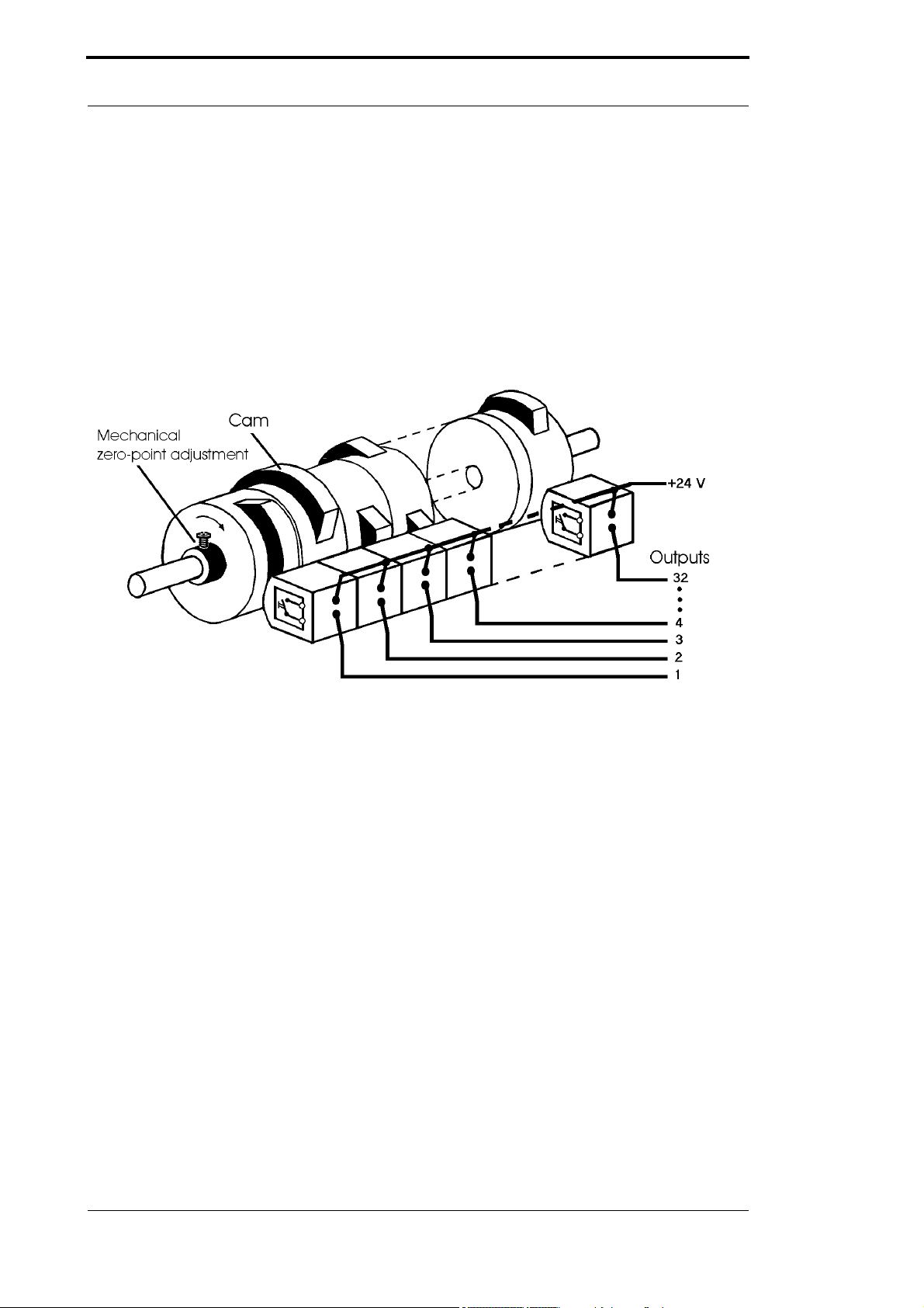
1.2 From the mechanical system to an electronic system
The purpose of electronic programming limit switches is not only to take the place of mechanical
controllers but to render their function more precise and simpler, to provide a universal range of
application and to reduce wear.
The mechanical cam control actuates a switch over sections of a circle, and this switch is closed
over the length of this section. Such a section is defined as a "cam".
Each switch represents one output. Several circuits arranged in parallel produce the number of
outputs.
Picture 1: Mechanical cam control
This basic principle has been adopted from the mechanical cam controls. A cam is programmed
for an output by entering a switch-on point and a switch-off point. The output is switched on
between these points.
Thanks to twenty years of experience, consistent further development and the use of ultra-mod-
ern technology, DEUTSCHMANN AUTOMATION has now become one of the leading suppliers
of electronic cam controls.
1.3 Deutschmann Automation’s range of products
See our homepage at http://www.deutschmann.de.

27.1.20 Instruction manual LOCON 15, TERM 4, 5, 6 V. 1.5 11
Deutschmann Automation GmbH & Co. KG EMC Directives for products of Deutschmann Automation
2 EMC Directives for products of Deutschmann Automation
The installation of our products has to be carried out considering the relevant EMC directives as
well as our internal instructions.
For more information see ’EMC Directives’ on our homepage at http://www.deutschmann.de.
Basic device LOCON 15 Deutschmann Automation GmbH & Co. KG
12 Instruction manual LOCON 15, TERM 4, 5, 6 V. 1.5 27.1.20
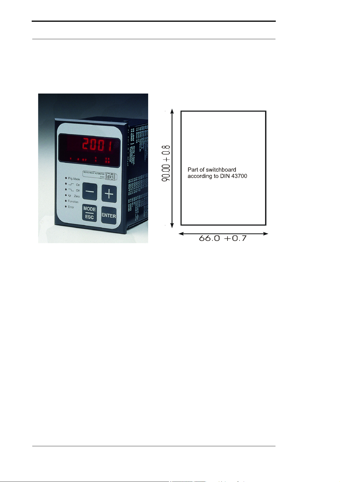
3 Basic device LOCON 15
The device LOCON 15 is a cam control with integrated operating front.
Picture 2: Front view LOCON 15 and part of switchboard

27.1.20 Instruction manual LOCON 15, TERM 4, 5, 6 V. 1.5 13
Deutschmann Automation GmbH & Co. KG Basic device LOCON 15
3.1 Technical dimensional drawings
3.1.1 LOCON 15
Picture 3: Technical dimensional drawing LOCON 15

Basic device LOCON 15 Deutschmann Automation GmbH & Co. KG
14 Instruction manual LOCON 15, TERM 4, 5, 6 V. 1.5 27.1.20
3.1.2 LOCON 15PM
Picture 4: Technical dimensional drawing LOCON 15

27.1.20 Instruction manual LOCON 15, TERM 4, 5, 6 V. 1.5 15
Deutschmann Automation GmbH & Co. KG Basic device LOCON 15
3.2 Pin assignment LOCON 15
Picture 5: Rear view LOCON 15
The screw-plug-connector X2 has 16 pins instead of 15 pins. For questions concerning the pin
assignment of previous devices, please contact DEUTSCHMANN AUTOMATION.
X1:
Assignment D-Sub
1Encodertrack 1
... ...
12 Encodertrack 12
13
14
24 +24V Power supply encoder (Output)
25 GND (encoder)
X2:
Assignment Screw-plug-connector
1Output 1
.. ...
16 Output 16
17 Reserve (do not wire) output 16
18 ProgNr. 1
19 ProgNr.2
20 ProgNr.4
21 ProgNr. 8
22 Program start
23 Program enable
24 +24V - Output
25 +24V - Power supply (Input)
26 GND
27 DICNET - (Rx-LOCON)
28 DICNET + (Tx-LOCON)
29 R-
30 R+
31 GND
32 Reserve (do not wire)

Basic device LOCON 15 Deutschmann Automation GmbH & Co. KG
16 Instruction manual LOCON 15, TERM 4, 5, 6 V. 1.5 27.1.20
3.3 Signal description LOCON 15
Function Significance
Output 1 ... Output 8 Output block 1
Each output 24V/0.3A positive switching (PNP), short-circuit proof
Total current of the output block max. 1A at 25°C and full load.
Output 9 ... Output 16 Output block 2
Each output 24V/0.3A positive switching (PNP), short-circuit proof
Total current of the output block max. 1A at 25°C and full load.
+24V - Output 24V-output for Prog-Enable and external program selection
+24V - Supply 24V-power supply of the total device incl. output drivers
+24V - Encoder 24V-output voltage to the encoder (max. 300 mA)
GND Ground potential of the total cam control. All GND-signals are interconnected
internally. There is no connection to the housing, that has to be connected to the
potential equalization.
Tx-LOCON RS232-transmission line
Rx-LOCON RS232-receive line
SSICLK+, SSICLK- RS422-timing line pair for SSI-connection
SSIDAT+, SSIDAT- RS422-data line pair for SSI-connection
DSI +, DSI - RS422-data line pair for DSI-connection
DICNET+, DICNET- Data line for the networking via the Deutschmann bus-system DICNET® (see
also chapter DICNET).
R+, R- Terminal resistance connections for DICNET. Required when LOCON 32 is ope-
rated as first or lasr device in DICNET (see chapter DICNET).
Encodertrack 1
- Encodertrack 12
24V-input (max. 10mA) for encoder lines when using absolute shaft encoders up
to 4096 Inf./rev. with parallel output.
InkTrackA Connection of track A when using an incremental encoder 24V
InkTrackB Connection of track B when using an incremental encoder 24V
Count^, Down+ In case of 24V at this input, the inputs „Encodertrack9“ and „Encodertrack10“ will
be interpreted as counting input and direction input. With each leading edge to
“Count1" an pulse is counted on. If the input "Down+" is at 24V it is counted bac-
kwards, otherwise forwards..
Clear-, Clear+ Clear-pulse. As soon as one of the two signals becomes active (0V at Clear-, 24V
at Clear+), the count will be set on 0 and it will be on 0 until the clear condition will
be disappearing again.
CountEnable- With 0V or unwired this signal releases the counter. In case this line is wired with
24V, the count is frozen. The speed measurement, and with it the idle time com-
pensation runs on in the meantime.
This signal is evaluated with an accuracy of ± 0.5ms.
OutEnable+ When using incremental encoders, with this signal the outputs can be switched
on or off. With 0V or unwired the outputs are switched off, with 24V the outputs
are set in accordance with the programed. The reaction to a signal change
occurs with an accuracy of ± 0.5ms.
ProgNr 1 ... ProgNr 32 The program number is applied at these pins in case of an external program
selection. The coding occurs in binary form according to chapter "Coding device
numbers".
ProgStart In case this pin is wired with 24V, the program number is taken over at the Pro-
gNr1 to ProgNr64 (see above).
ProgEnable In case this pin is wired with 24V, all parameter changes (including change of the
configuration) in LOCON are permitted.
nc Not connected

27.1.20 Instruction manual LOCON 15, TERM 4, 5, 6 V. 1.5 17
Deutschmann Automation GmbH & Co. KG Options
4Options
4.1 LOCON 15
4.1.1 Serial interface
LOCON features a RS232 and a RS485-interface. The interface can be switched manually. The
interface switch is to be found under the sticker with the imprint RS232/RS485. In the state of
delivery it is set as indicated on the marking of the sticker.The position of the desired interface
can be taken from the devices surprint. Please use an appropriate tool to change the position of
the microswitch to the left or to the right.
Please note the signal descriptions!
A support of both interfaces at the same time is not possible.
4.1.2 Storing output names and language (option M)
This standard option allows the storage of an output name with a maximum length of 16 charac-
ters and the selected language of an external operating unit. The number of data records
amounts to 1936.

Special versions Deutschmann Automation GmbH & Co. KG
18 Instruction manual LOCON 15, TERM 4, 5, 6 V. 1.5 27.1.20
5 Special versions
5.1 Connecting the supply voltage
The supply voltage is 10..30V DC (typ. 24V DC).
Before switching on the supply voltage the corresponding inputs and outputs must be wired, in
order to avoid malfunctions.
5.1.1 Connecting inputs and outputs
LOCON has 16 inputs (24V) and 16 24V-outputs.
Absolute shaft encoders are used as signaling devices of the machines. They are connected to
the pins ENCODER-TRACK1 to ENCODER-TRACK9 (360 Inc.-encoder).
The voltage supply of the encoders occurs through the 24V-encoder supply at the connector
strip. It may be loaded with a maximum of 500mA.
For the programming-release 24V must be applied at pin PROG_ENABLE (e. g. by means of a
key switch).
The pins PROG_NR1 to PROG_NR8 must only be wired, if an external program change is sup-
posed to happen (for instance via a PLC).
The outputs of LOCON are plus switching 24V, that means an active output has a level of 24V in
contrast to GND, a deleted output 0V.
The outputs are short circuit proof and can drive maximum 300mA, whereas 8 correlated outputs
of one driver can be operated with a maximum of 1A at 25°C and full load.
If more than 300mA per output become necessary, there is the possibility to couple more outputs
(up to 3 outputs each driver). Then 900mA can be driven. If several outputs are coupled, the
switch-on points and the switch-off points in the LOCON must be programmed absolutely identi-
cally. Otherwise the short circuit control reacts.
In case of a durable short circuit or an overload, the relevant outputs are switched off and a cor-
responding error message appears on the display.
5.2 Special versions
Beyond the diverse performance characteristics of the series LOCON 15 and TERM 5/6
described in this instruction manual, we also offer - as for all other models as well - customized
adaptations as well as special versions. If required please do not hesitate to send your inquiry
either to our distribution partner responsible for you or contact us directly.
If you are not sure about the device version, resp. the options you are
using, please compare the information indicated on the type label to the
explanations at the end of this instruction manual, chapter „Order code“.
For further questions either your distributor or we will be pleased to be at
your assistance.

27.1.20 Instruction manual LOCON 15, TERM 4, 5, 6 V. 1.5 19
Deutschmann Automation GmbH & Co. KG Basic device TERM 5/6 (external operating unit)
6 Basic device TERM 5/6 (external operating unit)
6.1 Assembly of the instrument
This external control- and display unit consists of a plastic housing with overall dimension
W72xH96xD18 mm for front sheet installation and W72xH96xT28 mm for DIN-rail mounting.
It is adjusted for programming cam controls (LOCON, ROTARNOCK) and has the same keys,
status LEDs and display possibilities as LOCON 1/2 and LOCON 16/17.
In this respect the programming is just like LOCON 1/2 and LOCON 16/17 and no additional
training is required.
On the 16 LEDs below the seven-segment-display the first 16 outputs of the connected cam con-
trols are displayed with a delay of maximum 500ms.
The connection to the cam control takes place via aserial wire. According to the standard type a
RS485-connection (DICNET) and optionally a RS232-connection (switchable at the device) is
supported.
The correct wiring of the instruments among themselves is described in the chapter "Networking
terminals with cam controls and PCs".
6.2 View TERM 5/6
Picture 6: TERM 5 / TERM 6

Basic device TERM 5/6 (external operating unit) Deutschmann Automation GmbH & Co. KG
20 Instruction manual LOCON 15, TERM 4, 5, 6 V. 1.5 27.1.20
6.3 Technical dimensional drawings
6.3.1 TERM 5 / TERM 6
Picture 7: Technical dimensional drawing TERM 5 / TERM 6
This manual suits for next models
10
Table of contents
Other DEUTSCHMANN AUTOMATION Controllers manuals


Popular Controllers manuals by other brands

Eaton
Eaton xComfort CSAU-01/01-10I Assembly instructions/use and care manual

Helios
Helios ESD Installation and operating instructions

Northern Lights
Northern Lights OWN-ADV Installation and user manual

Rigel
Rigel usb-nSTEP instructions

Trinity
Trinity Goblin user manual

Chino
Chino JU Series instruction manual


