DeWalt DXSTFB048 User manual

IMPORTANT:
Please read this manual carefully before assembling this
garage bench and save it for reference
DXSTFB048
GARAGE BENCH
INSTRUCTION
MANUAL


3
SAVE THESE INSTRUCTIONS
This manual contains important safety and operating
instructions. Read all instructions and follow them with
use of this product.
TABLE OF CONTENTS
TECHNICAL SPECIFICATIONS 4
SAFETY GUIDELINES 5
PARTS LIST 6
ASSEMBLY 8
WARRANTY 11
TABLE OF CONTENTS

4
DXSTFB048
TECHNICAL SPECIFICATIONS
SEAT CAPACITY 1,000 lb (454 kg)
*WHEN WEIGHT IS EVENLY DISTRIBUTED
SHELF CAPACITY 1,500 lb (680 kg)
*WHEN WEIGHT IS EVENLY DISTRIBUTED
HEIGHT 19.75" (50.16 cm)
WIDTH 49.6" (126 cm)
DEPTH 15" (38.1 cm)
WEIGHT 48 lb (21.77 kg)
TECHNICAL SPECIFICATIONS

5
SAFETY GUIDELINES
• Save all warnings and instructions for future reference.
• This manual contains important safety and assembly
instructions. Read all instructions and follow them with
the use of this product.
FPO
GENERAL SAFETY
• Keep work area clean and dry.
• Use correct/recommended tools for the job.
• Never leave unattended tools plugged in or running.
• Never force a part into place.
• Wear appropriate safety apparel for the job you are doing.
• Wear safety glasses/goggles.
• Keep small parts away from children. Never leave a small child unattended while assembling.
• Always use common sense – your personal safety is your responsibility.
NEVER EXCEED THE FOLLOWING WEIGHT LIMITS FOR THIS BENCH
• Maximum load for bench seat: Up to 1,000 lb (454 kg) when weight is evenly distributed.
• Maximum load for shelf: Up to 1,500 lb (680 kg) when weight is evenly distributed.
• It is recommended that the heaviest load be placed on the bottom shelf.

6
DXSTFB048
PARTS LIST
No. Description
1 Cushion Seat
2 Pre-Bolted Upright Assembly
3 Wire Deck
4 Crossbeam
5Bench Top Support Strap (Black)
6Recessed Shelf Support Strap (Yellow)
No. Description
7 Safety Strap With Weld Nut
8 Safety Strap Bolt
9 Locking Shelf Pin
10 4 mm Hex Key
11 4 mm Hex Bit
12 Locking Grid Clip
6
5
7
BEFORE YOU BEGIN:
• Read all instructions thoroughly.
• Remove all components from the box, and lay them on the floor in an orderly fashion.
• Wear eye protection.
• Be cautious of sharp edges.
• Keep this information for further reference.
FPO
8
9
11
1
2
1
4
4
3
4
8
12
1
1
4
Qty. Qty.
12
10

7
1
4
3
PARTS LIST
Tools Required for Bench Assembly: 4 mm Hex Key (included) OR 4 mm Hex Bit (included);
Rubber Mallet (not included), Flat-Head Screwdriver (not included)
2

8
DXSTFB048
ASSEMBLY
CROSSBEAM INSTRUCTIONS
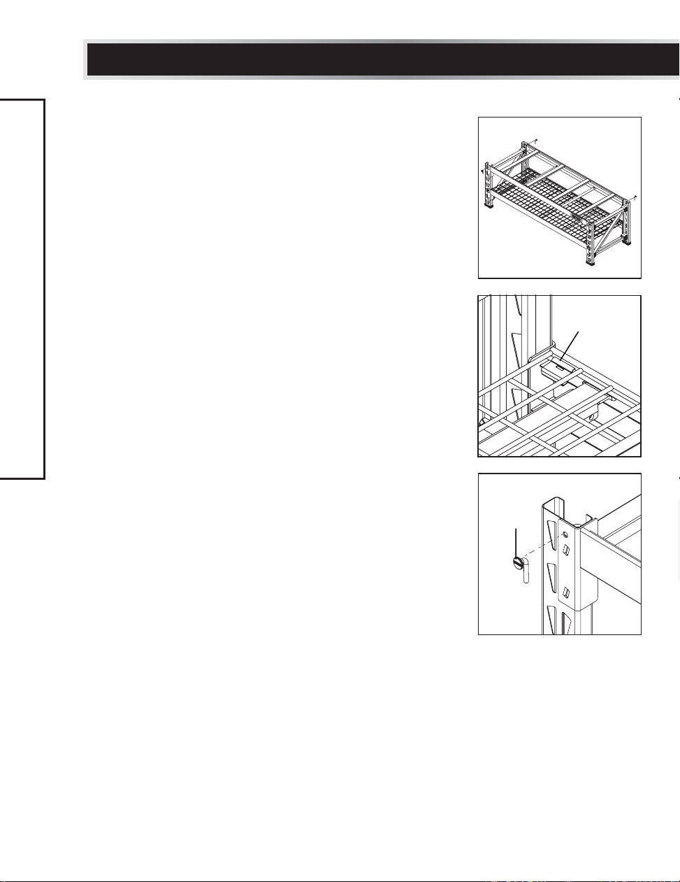
• Note: It is recommended for one person to hold the
pre-assembled upright frames in place while a second person
installs the crossbeams.
• Note: Keep the bolt heads of the diagonal pieces of the uprights
on the outside of the assembly (*see first image).
• Note: The top crossbeams have 4 slots for their associated
bench support straps, and the bottom crossbeams have 3
slots for their associated support straps.
STEP 1
• There is a set of locking tabs at both ends of every crossbeam.
To begin assembly, take a crossbeam with 3 slots and insert
the tabs into two of the holes on the lower portion of one
upright frame. Engage the locking tabs into the holes using
a downward motion. The locking bolt hole should be at the
top. Make sure the end of the crossbeam is flush against the
upright frame.
STEP 2
• Repeat for the opposite side of the upright frame. Tap the ends
of the crossbeam closest to the upright frames with a rubber
mallet until fully seated. The crossbeam and locking tabs
should easily slip into place. If they do not, then recheck the
alignment of the teardrop-shaped holes and tabs. Too much
force may damage the interlock between the crossbeam and
upright frame.
STEP 3
• Using the methods listed above, install the other crossbeam
with 3 slots to the opposite side of the upright frames,
parallel to the first crossbeam you installed. Make sure both
crossbeams are at the same level.
STEP 4
• Continue by installing the top sets of crossbeams flush to the
top of the upright frames (each top crossbeam has 4 slots and
one will have the DEWALT®badge on the far right). Make sure
the crossbeams are attached at the same level on both sides.
LOCKING
PIN HOLE
UPRIGHT
FRAME
*KEEP BOLT
HEADS OF
DIAGONAL
PIECE ON
OUTSIDE OF
ASSEMBLY

9
ASSEMBLY
• Note: There are two (2) safety straps with weld nuts and
three (3) recessed shelf support straps on the bottom set
of crossbeams.
• Note: There are two (2) safety straps with weld nuts and
four (4) bench top support straps on the top set
of crossbeams.
• Note: Top and bottom crossbeams use different support straps.
STEP 1
• Starting with the bottom set of crossbeams, place a safety
strap with weld nut between the lower ridges of the crossbeams
where two sets of holes have been pre-drilled. Thread a safety
strap bolt up through the bottom of the pre-drilled holes and
through the weld nuts, and fully tighten with the included
hex key or drill bit. Repeat for the second strap on this set of
crossbeams, and continue for the last 3 straps.
STEP 2
• On the bottom of the bench, place a recessed shelf support
strap (yellow) perpendicular to the bottom crossbeams,
and insert each end into the channel on each ridge of the
crossbeam. Repeat for the remaining 2 (yellow) straps.
STEP 3
• On the top of the bench, place a bench top support strap
(black) perpendicular to the top crossbeams, and insert each
end into the channel on each ridge of the crossbeam. Repeat
for the remaining 3 (black) straps.
SAFETY STRAP AND SUPPORT STRAP INSTRUCTIONS
BENCH TOP
SUPPORT STRAPS (BLACK)
RECESSED SHELF
SUPPORT STRAPS
(YELLOW)
SAFETY STRAP
WITH WELD NUT
SAFETY STRAP
WITH WELD NUT
CROSSBEAM
RECESSED SHELF
SUPPORT STRAPS ON
BOTTOM CROSSBEAMS
TOP BENCH
SUPPORT STRAPS ON
TOP CROSSBEAMS

10
DXSTFH048
ASSEMBLY
WIRE GRID AND LOCKING SHELF PIN INSTRUCTIONS
• Note: The wire grid consists of two sides – a “short” side
and “long” side. If you plan on sliding objects on and off of
the shelf from the front of the bench, then we recommend
having the “short” side of the grid facing upward. If you
plan on sliding objects from the side of the bench , then we
recommend having the “long” side facing upward.
STEP 1
• Place the wire grid onto the top ridge of the lower set of
crossbeams. If seated properly, the grids will “pop” into place
and lay evenly.
STEP 2
• Place a locking grid clip at the outermost corner of the shelf.
Make sure the rolled edge with the groove is facing upwards.
STEP 3
• With one hand, apply pressure to the back of the clip. With
your free hand, insert a flat-head screwdriver (not included)
into the small slot in the clip to spread the tine up and over the
wire that is underneath.
STEP 4
• Pull back on the screwdriver. The grooved channel in the clip
should now match up with the wire decking, which will help
secure it to the shelf beam.
STEP 5
• Repeat Steps 2-4 for the remaining three corners of the wire grid.
STEP 6
• There is a locking pin hole at both ends of every crossbeam.
This is where the locking shelf pins are to be installed. If a pin
does not easily slip into place, then moderately tap the end of
the crossbeam to fully seat the locking tabs.
FPO
LOCKING GRID
CLIP
LOCKING
SHELF PIN INTO
LOCKING PIN
HOLE ON
CROSSBEAM

11
CUSHION SEAT INSTRUCTIONS
• Note: Place onto the frame as evenly as possible to ensure the
cushion seats properly.
STEP 1
• Place cushion seat onto the assembled bench frame. The
corner brackets of the cushion seat slide over the outer edges
of the upright frame.
STEP 2
• There is a locking pin hole on each corner bracket of the
cushion seat. This is where the locking shelf pins are to be
installed. If a pin does not easily slip into place, sit on the
corner of the bench to fully seat the locking tabs.
11
TWO YEAR LIMITED WARRANTY:DEWALT®will replace this garage bench due to faulty materials or workmanship for
two years from the date of purchase (be sure to keep your receipt). This warranty does not cover part failure due to normal wear or
bench abuse. This warranty does not apply to accessories or damage caused where repairs have been made or attempted.
For further detail of warranty coverage, call 1-844-377-8451.
In addition to the warranty, DEWALT®garage benches are covered by our:
90 DAY MONEY BACK GUARANTEE: If you are not completely satisfied with the performance of your DEWALT®Garage
Bench for any reason, you can return it within 90 days from the date of purchase with a receipt for a full refund – no questions asked.
LATIN AMERICA: This warranty does not apply to products sold in Latin America. For products sold in Latin America, see
country specific warranty information contained in the packaging, call the local company or see website for warranty information.
WARRANTY
CUSHION
SEAT
LOCKING
PIN HOLE
LOCKING
SHELF PIN
CORNER
BRACKET
UPRIGHT
FRAME
• Do not stand on this product. You may fall
which may cause personal injury.
FPO
JS PRODUCTS • 6445 MONTESSOURI STREET, LAS VEGAS, NV 89113
Copyright © 2018 DEWALT.
DEWALT®and the DEWALT Logo are trademarks of the DEWALT Industrial Tool Co., or an affiliate thereof and are used under license. The yellow/
black color scheme is a trademark for DEWALT power tools & accessories. Product may differ from that pictured. Does not affect function.

Other manuals for DXSTFB048
1
Table of contents
Other DeWalt Indoor Furnishing manuals

DeWalt
DeWalt DXST4500BLK-W User manual

DeWalt
DeWalt DXST4500-W User manual

DeWalt
DeWalt DXST4500 User manual

DeWalt
DeWalt DXST10000BLK User manual

DeWalt
DeWalt DXSTAH025 User manual

DeWalt
DeWalt DXST4500BLK User manual

DeWalt
DeWalt DXST4500 User manual

DeWalt
DeWalt DXSTFH030 User manual

DeWalt
DeWalt DXSTAH025 User manual

DeWalt
DeWalt DXSTAH025 User manual
Popular Indoor Furnishing manuals by other brands

Carmelli
Carmelli Park Avenue NG2530PR Assembly instructions

Furniture of America
Furniture of America CM3001T-5PK Assembly instructions

OVE
OVE GABLES 30 installation manual

Sauder
Sauder Orchard Hills 418651 manual

Hooker Furniture
Hooker Furniture 5149-75003 Assembly instruction

Forte
Forte RGMK235 Assembling Instruction