English
angle.
STEP 29. Clean the table top. Your saw was shipped with
a rust preventive coating which should be removed. Clean
the top with mineral spirits or denatured alcohol and apply
paste wax. Apply and remove soon afterward to prevent a
sticky build-up.
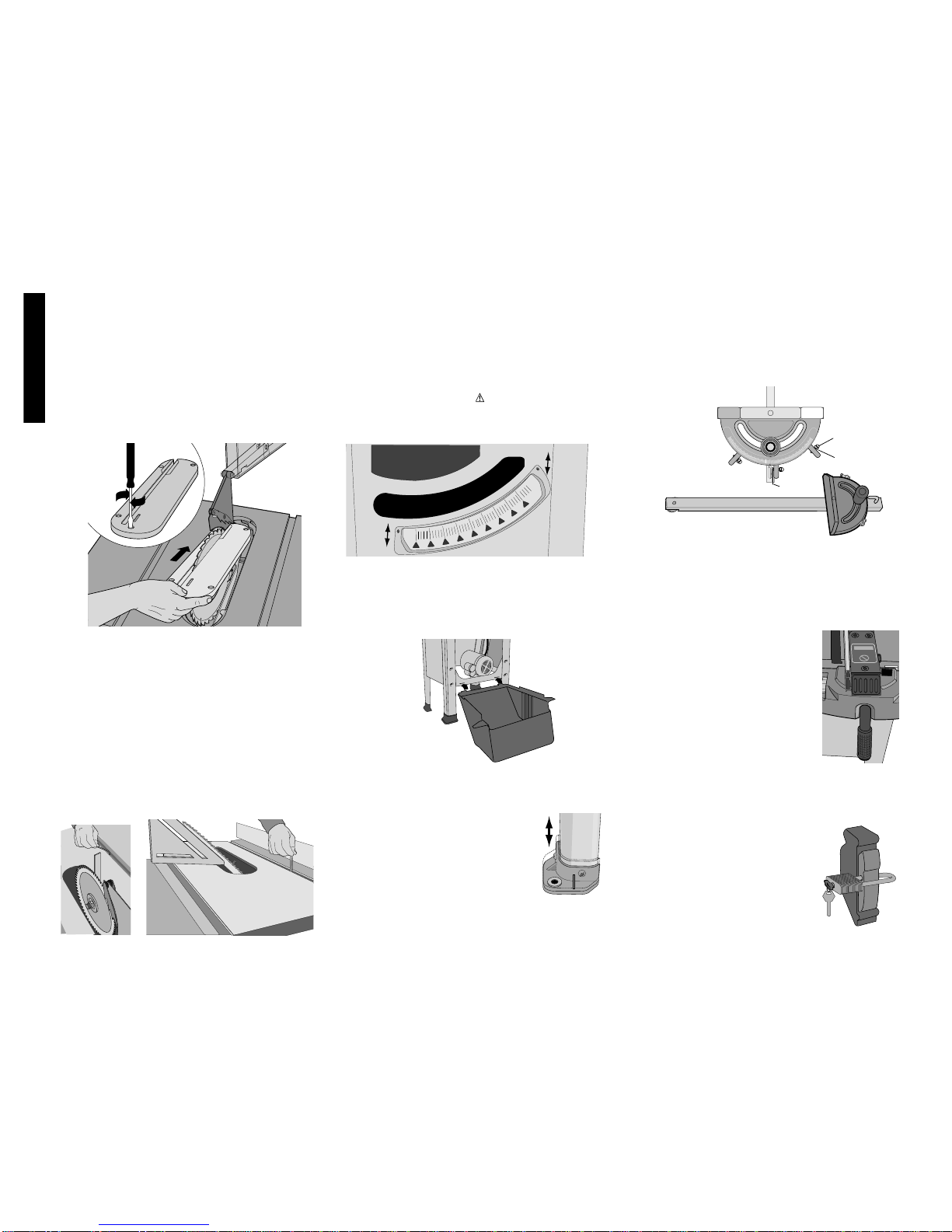
Rip Fence Operation
FENCE LOCK LEVER
The fence lock lever locks the rip fence in place, preventing
movement. To lock the fence, push down. To unlock the
lever, pull it up. NOTE: When ripping, always lock the fence
to the rail.
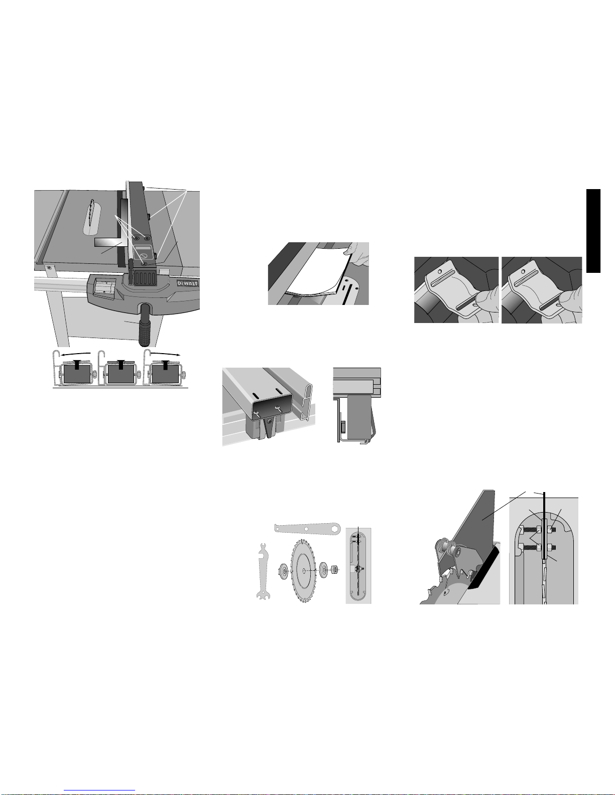
RIP SCALE POINTER
NOTE: The rip scale pointer will need to be readjusted
whenever a thicker or thinner blade is installed. Should
you decide to use a thicker face, or the DEWALT low fence
face accessory, the scale pointer may be removed and
turned 180˚to line up with the scale. (Fig. 12)
RIP FENCE CAPACITY
The fence will slide beyond the end of the rails in either
direction without falling off. Stops are provided to keep the
fence attached.
On-Off Switch
Pull out the switch paddle to turn your saw ON and push it
in to turn your saw OFF. A hole is provided in the switch
for insertion of a padlock to lock the saw off.
WARNING: Be sure switch is in the OFF position before
plugging machine in.
Saw Blades
THIS SAW IS INTENDED FOR THE USE WITH SAW
BLADES 10”IN DIAMETER OR SMALLER.
1. The saw blade furnished with your new saw is a 10"
(254mm) fine ripping blade, used for ripping (with the
grain) through the material, and occasional cross cuts.
The center hole to fit on the arbor is 5/8" (16mm)
diameter (.625"). This blade will produce a good quality
cut for many applications.
2. There are many types of blades available to do specific
and special jobs such as cross cut only, rip only, hollow
ground, thin plywood, paneling, etc.
3. Use only saw blades designed for maximum safe
operating speeds of 5,000 RPM or greater.
4. Saw blades should always be kept sharp. It is
recommended that you locate a reputable sharpening
service to sharpen your blades when needed.
5. Never stack blades on top of one another to store. Place
material such as cardboard between them to keep the
blades from coming in contact with one another.
CAUTION: Abrasive wheels should not be used on this
saw.
Operation
Plain sawing includes ripping and cross cutting, plus a few
other standard operations of fundamental nature. With all
power tools, respecting the tool, using caution and following
safe practices will considerably lessen the possibility of
personal injury. However, if normal safety precautions are
overlooked or completely ignored, personal injury to the
operator can result. Read and follow all warnings indicated
on the saw. Familiarize yourself with all the components
and features before attempting any cuts. Know how to
make adjustments before turning the saw on. Observe the
safety rules included in this manual.
THIS SAW IS NOT INTENDED FOR CUTTING METAL.
Operating Instructions
There are two basic types of cuts: ripping and crosscutting.
In general, cutting with the grain is ripping and across the
grain is crosscutting. However, with man made materials
this distinction is somewhat difficult to make. Therefore,
cutting a piece of wood to a different width is ripping and
cutting across the short dimension is crosscutting. Neither
ripping or crosscutting may be done safely freehand!
Ripping requires the use of the rip fence and crosscutting
uses the miter gauge.
CAUTION: Before using the saw each and every time
verify the following:
1. Blade is tight.
2. Bevel angle and height lock knobs are tight.
3. If ripping, ensure fence lock lever is tight and fence is
parallel to the blade.
4. If crosscutting, miter gauge knob is tight.
5. Safety glasses are being worn.
6. The blade guard is properly attached and the
anti-kickback teeth are functioning.
Failure to adhere to these common safety rules can greatly
increase the likelihood of injury.
Ripping
1. Lock the rip fence by pressing the fence lock lever
down. Remove the miter gauge.
2. Raise the blade so it is about 1/8"(3.2mm) higher than
the top of the workpiece.
3. Hold the workpiece flat on the table and against the
fence. Keep the workpiece about 1" (25.4mm) away
from the blade.
CAUTION: The workpiece must have a straight edge
against the fence and must not be warped, twisted or
bowed. Keep both hands away from the blade and away
from the path of the blade.
4. Turn the saw on and allow the blade to come up to
speed. Both hands can be used in starting the cut.
When there is approximately twelve (12) inches
(305mm) left to be
ripped, use only one hand, with your thumb pushing the
material, your index and second finger holding the
material down and your other fingers hooked over the
fence. Always keep your thumb along side your first two
fingers and near the fence.
5. Keeping the workpiece against the table and fence,
slowly feed the workpiece rearward all the way through
the saw blade. Continue pushing the workpiece until it is
clear of the guard and it falls off the rear of the table. Do
not overload the motor.
6. NEVER try to pull the workpiece back with the blade
turning. Turn the switch off, allow the blade to stop, raise
the anti-kickback teeth on each side of the splitter if
necessary and slide the workpiece out.
7. When sawing a long piece of material or a panel, always
use a work support. A sawhorse, rollers, or out feed
assembly provides adequate support for this purpose. The
work support must be at the same height as the saw
table.
CAUTION: Never push or hold onto the “free”or “cut
off”side of the workpiece.
Bevel Ripping
This operation is the same as ripping except the bevel
angle is set to an angle other than zero degrees.
WARNING: Before connecting the table saw to the
power source or operating the saw, always inspect the
guard and splitter for proper alignment and clearance with
saw blade. Check alignment after each change of bevel
angle.
Ripping Small Pieces
It is unsafe to rip small pieces. It is not safe to put your hands
close to the blade. Instead, rip a larger piece to obtain the
desiredpiece.When a smallwidthis toberipped and thehand
cannot be safely put between the blade and the rip fence, use
one or more push sticks. A pattern is
included on the back cover to make
push sticks. Use them to hold the
workpiece against the table and
fence, and push the workpiece fully
past the blade
Crosscutting
1. Remove the rip fence and place
the miter gauge in the desired
slot.
2. Adjust the blade height so that
the blade is about 1/8" (3.2mm)
higher than the top of the
workpiece.
3. Hold the workpiece firmly
against the miter gauge with the path of the blade in line
with the desired cut location. Keep the workpiece an inch
7