DeWalt DW712 User manual

IF YOU SHOULD EXPERIENCE A PROBLEM WITH YOUR DEWALT PURCHASE,
CALL 1-800-4 DEWALT
IN MOST CASES, A DEWALT REPRESENTATIVE CAN RESOLVE YOUR PROBLEM
OVER THE PHONE.
IF YOU HAVE A SUGGESTION OR COMMENT, GIVE US A CALL.
YOUR FEEDBACK IS VITAL TO THE SUCCESS OF DEWALT'S QUALITY
IMPROVEMENT PROGRAM.
Questions? See us on the World Wide Web at www.dewalt.com
INSTRUCTION MANUAL
GUIDE D'UTILISATION
MANUAL DE INSTRUCCIONES
INSTRUCTIVO DE OPERACION, CENTROS DE SERVICIO Y POLIZA
DE GARANTfA. ADVERTENCIA: LF::tASEESTE INSTRUCTIVO ANTES
DE USAR EL PRODUCTO.
®
DW712
8-1/2" (216 mm) Sliding Compound Miter Saw
Scie &onglets combin_e &chariot de 216 mm (8-1/2 po)
Sierra de inglete compuesto deslizable de 216 mm (8-1/2")


TABLE OF CONTENTS
IMPORTANT SAFETY INSTRUCTIONS FOR ALL TOOLS .................................... 2
ADDITIONAL SAFETY INSTRUCTIONS FOR
SLIDING COMPOUND MITER SAWS........................................................................ 2
ELECTRICAL CONNECTION AND MOTOR ........................................................... 4
UNPACKING YOUR SAW ....................................................................................... 4
FAMILIARIZATION .................................................................................................. 4
CONTROLS ............................................................................................................. 4
SPECIFICATIONS ................................................................................................... 4
OPTIONAL ATTACHMENTS/ACCESSORIES ....................................................... 5
BLADE RECOMMENDATIONS .............................................................................. 5
BENCH MOUNTING ............................................................................................... 5
TRANSPORTING THE SAW .................................................................................. 5
ADJUSTMENTS ...................................................................................................... 5
GUARD ACTUATION AND VISIBILITY .................................................................. 6
AUTOMATIC ELECTRIC BRAKE .......................................................................... 6
BRUSHES ............................................................................................................... 6
OPERATION ............................................................................................................ 7
SWITCH ................................................................................................................... 7
CUTTING WITH YOUR SAW ................................................................................. 7
CROSSCUTS .......................................................................................................... 7
QUALITY OF CUT ................................................................................................... 7
BODY AND HAND POSITION ................................................................................ 7
CLAMPING THE WORKPIECE .............................................................................. 7
SUPPORT FOR LONG PIECES ............................................................................. 7
PRECISION CUTTING ............................................................................................ 7
GRAPH 1: COMPOUND MITER CUTS ................................................................. 9
BOWED MATERIAL .............................................................................................. 10
CUTTING PLASTIC PIPE OR OTHER ROUND
CROSS-SECTIONAL MATERIAL ......................................................................... 10
CUTTING LARGE MATERIAL .............................................................................. 10
GROOVING ........................................................................................................... 10
ALUMINUM CUTTING .......................................................................................... 11
MAINTENANCE ..................................................................................................... 11
INSTALLING A NEW SAW BLADE ....................................................................... 11
WARRANTY ........................................................................................................... 11
TROUBLESHOOTING GUIDE ............................................................................. 13

IFYOUHAVEANYQUESTIONSORCOMMENTSABOUTTHISORANYDEWALTTOOL,
CALLUSTOLLFREEAT:1-800-4-DEWALT(1-800-433-9258)
Important Safety Instructions for All Tools
_ARNING: For your own safety, read the instruction manual before operating the
sliding compound miter saw. Failure to heed these warnings may result in person-
al injury and serious damage to the saw. When servicing this tool use only identical
replacement parts. Have damaged cords replaced by an authorized service center.
DOUBLE INSULATION
Double insulated tools are constructed throughout with two separate layers of electrical insula-
tion or one double thickness of insulation between you and the tool's electrical system. Toolsbuilt
with this insulation system are not intended to be grounded. As a result, your tool is equipped
with a two prong plug which permits you to use extension cords without concem for maintaining
a ground connection.
NOTE: Double insulation does not take the place of normal safety precautions when operating
this tool The insulation system is for added protection against injury resulting from a possible
electrical insulation failure within the tool.
POLARIZED PL UGS
Toreduce the risk of electric shock, this equipment has apolarized plug (one blade is wider than
the other). This plug will fit in a polarized outlet only one waF If the plug does not fit fully into the
outlet, reverse the plug. If it still does not fit, contact a qualified electrician to install the proper
outlet. Do not change the plug in any waF
AWARNING: When using electric tools, basic safety precautions should always be followed
to reduce the risk of fire, electric shock, and personal inju_ including the following:
•KEEP GUARDS IN PLACE and in working orde_
• REMOVE ADJUSTING KEYS AND WRENCHES. Form habit of checking to see that keys
and adjusting wrenches are removed from tool before turning it on.
• KEEP WORK AREA CLEAN. Cluttered areas and benches invite injuries.
• DON'T USE IN DANGEROUS ENVIRONMENT. Don't use power tools in damp or wet loca-
tions, or expose them to rain or snow Keep work area weft lighted. Always operate tool in a
well-ventilated area free of combustible materials, gasoline or solvent vapors. If sparks come
in contact with flammable vapors, they may ignite, causing fire or explosion.
• KEEP CHILDRENAWAY. All visitors should be kept safe distance from work area.
• MAKE WORKSHOP KID PROOF with padlocks, master switches, orby removing starter keys.
•DON'T FORCE TOOL. It will do the job better and safer at the rate for which it was designed.
• USE RIGHT TOOL. Don't force tool or attachment to do ajob for which it was not designed.
• USE PROPER EXTENSION CORD. Make sure your extension cord is in good condition.
When using an extension cord, be sure to use one heavy enough to carry the current your
product will draw An undersized cord will cause a drop in line voltage resulting in overheating
and loss ofpowe_ The following table shows the correct size to use depending on cord length
and nameplate ampere rating. If in doubt, use the next heavier gage. The smaller the gage
number, the heavier the cord.Minimum Gage for Cord Sets
Volts
120V 0-25
240V 0-50
Ampere Rating
More Not more AWG
Than Than
0 6 18 16 16 14
6 10 18 16 14 12
10 - 12 16 16 14 12
12 - 16 14 12 Not Recommended
Total Length of Cord in Feet
26-50 51-100 101-150
51-100 101-200 201-300
• WEAR PROPER APPAREL. Do not wear loose clothing, gloves, neckties, rings, bracelets, or
other jewelry which may get caught in moving parts. Non-slip footwear is recommended. Wear
protective hair covering to contain long hair.Air vents often cover moving parts and should also
be avoided.
•ALWAYS USE SAFETY GLASSES. Also use face or dust mask if cutting operation is dust}<
Everyday eyeglasses only have impact resistant lenses, they are not safety glasses.
•SECURE WORK. Use clamps or vise when you cannot secure the workpiece on the table
and against the fence by hand or when your hand will be dangerously close to the blade
(within 6").
• DON'T OVERREACH. Keep proper footing and balance at all times.
• MAINTAIN TOOLS WITH CARE. Keep tools sharp and clean for best and safest
performance. Follow instructions for lubricating and changing accessories.
• DISCONNECT TOOLS before servicing; when changing accessories, such as blades,
clamps, extensions, and the like.
•REDUCE THE RISK OF UNINTENTIONAL STARTING. Make sure switch is in off position
before plugging in.
• USE RECOMMENDED ACCESSORIES. Consult the instruction manual for recommended
accessories. The use of improper accessories may cause risk of injury to persons.
• NEVER STAND ON TOOL. Serious injury could occur if the tool is tipped orif the cutting tool
is unintentionally contacted.
• CHECK DAMAGED PARTS. Before further use of the tool a guard or other part that is
damaged should be carefully checked to determine that it will operate properly and perform its
intended function. Check for alignment of moving parts, binding of moving parts, breakage of
parts, mounting, and any other conditions that may affect its operation. A guard or other part
that is damaged should be properly repaired or replaced.
• NEVER LEA VE TOOL RUNNING UNATTENDED. TURN POWER OFF. Don't leave tool until
it comes to a complete stop.
Additional Safety Instructions for Sliding Compound
Miter Saws
• Use safety equipment. Always wear eye protection. Dust mask, non-skid safety shoes,
hard hat, or hearing protection must be used for appropriate conditions.
• Keep hands out ofpath of saw blade. NEVER CUTA PIECE WHERE HAND WOULD BE
CLOSER THAN 6" (152 ram) TO THE BLADE.
•Do not operate saw without guards in place.
• Do not perform any operation freehand, that is without holding or clamping the workpiece
against the fence and saw table.
•Never reach in back of saw blade.
• Tumofftoolandwaitforsawbladetostopbeforemovingworkpieceorchangingsettings.
• Disconnectpowerbeforechangingbladeorservicing.
• Blade adjustmentis to be made only with thepoweroffandthe blade stopped.
•Never use saw without kerfplate.
• Replace kerfplate when itis wom.
• To reduce risk of injury, return carriage to the full rear position after each crosscut
operation.
• DO -Protect electric supply line with at least a 15 ampere time-delay fuse or a circuit
breake_
• DO -Make certain the blade rotates in the correct direction and that the teeth at the bottom
of the blade are pointing to the rear of the sliding compound miter saw
• DO use the stabilizerbaratall times.
• DO -Be sure all clamp handles and knobs are tight before starting any operation.
•DO -Be sure all blade and clamp washers are clean and recessed sides of collars are
against blade. Tighten arbor screw securelF

•DO -Keep the saw blade sharp andproperly aligned.
•DO -Keep the motorairslots free ofchips and dirt.
• DO -Use blade guard at all times.
• DO -Keep hands out of the path of the saw blade.
•DO -Shut off power, unplug and wait for saw blade to stop before servicing or adjusting
tool.
• DO -Supportlong work with an outboard tool rest.
• DON'T -Attempt to operate on anything but designated voltage. Incorrect voltage may
result in shock, fire, or unpredictable operation.
•DON'T -Operate unless all knobs and clamp handles are tight.
• DON'T- Use blades larger orsmaller than those which are recommended.
• DON'T -Wedge anything against fan to hold motor shaft.
•DON'T -Force cutting action. Allow motor to reach full speed before cutting. Stalling
or partial stalling of motor can cause major damage.
• DON'T -Cut ferrous metals (those with any iron or steel content), any masonry, or fiber
cement products.
• DON'T -Use abrasive wheels. The excessive heat and abrasive particles generated by
them will damage the saw.
• DON'T -Use any abrasive blades.
• DON'T -Allow anyone to stand behind saw
•DON'T-Applylubricants to the blade when it's running.
• DON'T -Place either hand in the blade area when the saw is connected to the power
source.
• DON'T- Use blades ratedless than 6000 R.RM.
• DON'T -Attempt to cut small pieces -- 6" (152mm) -- without clamping.
•DON'T -Place hands closer than 6" to the blade.
•DON'T -Reach behind or underneath the saw unless it is turned off and unplugged.
• DON'T -Move eitherhand from saw or workpiece or raise arm until blade has stopped.
• DON'T -Use lubricants or cleaners, particular spray or aerosol cleaners, in the vicinity of
the plastic guard. Thepolycarbonate material used in the guard is subject to deterioration
by certain chemicals
CAUTION: Wear appropriate hearing protection during use. Under some conditions and
duration of use, noise from this product may contribute to hearing loss.
CAUTION: Do not connect unit to electrical power source until complete instructions are
read and understood.
AWARNING: Some dust created by power sanding, sawing, grinding, drilling, and other con-
struction activities contains chemicals known to cause cancer, birth defects or other reproduc-
tive harm. Some examples of these chemicals are:
•lead from lead-based paints,
• crystalline silica from bricks and cement and other masonry products, and
• arsenic and chromium from chemically-treated lumber (CCA).
Your risk from these exposures varies, depending on how often you do this type of work. To
reduce your exposure to these chemicals: work in a well ventilated area, and work with
approved safety equipment, such as those dust masks that are specially designed to filter out
microscopic particles.
•Avoid prolonged contact with dust from power sanding, sawing, grinding, drilling,
and other construction activities. Wear protective clothing and wash exposed areas
with soap and water. Allowing dust to get into your mouth, eyes, or lay on the skin may pro-
Amote absorption of harmful chemicals.
WARNING: Use of this tool can generate and/or disburse dust, which may cause serious and
permanent respiratory or other injury Always use NIOSH/OSHA approved respiratory protection
appropriate for the dust exposure. Direct particles away from face and body
AWARNING: ALWAYS use safety glasses. Everyday eyeglasses are NOT safety glasses.
Also use face or dust mask if cutting operation is dusty. ALWAYS WEAR CERTIFIED SAFE-
TY EQUIPMENT
• ANSI Z87.1 eye protection (CAN/CSA 7_94.3);
• ANSI $12.6 ($3.19) hearing protection;
•NIOSH/OSHA/MSHA respiratory protection.
• The label on your tool may include the following symbols.
V.......... volts
Hz ........hertz
min ......minutes
.... ....direct current
[] ........Class II Construction
& ........safety alert symbol
A.......... amperes
W.......... watts
"_J ........altemating current
no ........no load speed
G .......... earthing terminal
.../min.... revolutions per minute
For your convenience and safety, the following waming labels are on your miter saw
ON MOTOR HOUSING:
_,WARNING: FOR YOUR OWN SAFETY, READ INSTRUCTION MANUAL BEFORE
OPERATING MITER SAW.
ALWAYS WEAR EYE PROTECTION.
Double insulated. WHEN SERVICING, USE ONLY IDENTICAL REPLACEMENT PARTS.
Do not expose to rain or use in damp locations.
ON MOVING FENCE."
&ALWAYS ADJUST FENCE
PROPERLY BEFORE USE.
CLAMP SMALL PIECES BEFORE
CUT_NG. SEE MANUAL.
ALWAYSADJUSTFENCEPROPERLYBEFOREUSE,
CLAMPSMALLPIECESBEFORECUTTING,SEEMANUAL,
AJUSTE LAGUIADEBJDAMENTEANTESDE UTJLJZARLA
HERRAMJENTA,ASEGURELAS PiEZASPEQUENASANTES DE
CORTARLAS.CONSULTEELMANUAL
TOUJOURSREGLERLE GUIDEAVANTL'UTJLiSATiON.FIXERLES
PETITSORJETSAVANT DE LESSCIER,CONSULTERLEGUIDE
ON GUARD."
_DANGER- KEEPAWAYFROM BLADE
ONARM."
PROPERLYSECUREBRACKET _THBOTHSCREWSBEFORE
US£
KEEPAWAY
FROM BLADE
MANTENERSALEJADO
DELA HOJA
S'€:LOiGNERDELA LAME
ON BASE."
&
_WARNING: FOR YOUR OWN SAFETY READ INSTRUCTION
MANUAL BEFORE OPERATING MITER SAW,
KEEP HANDS OUT OF PATH OF SAW BLADE.
DO NOT OPERATE SAW WITHOUT GUARDS IN PLACE.
Check lower guard for proper closing before each use.
ALWAYS TIGHTEN ADJUSTMENT KNOBS BEFORE USE.
DO NOT PERFORM ANY OPERATION FREEHAND.
NEVER REACH IN BACK OF SAW BLADE.
NEVER CROSS ARMS IN FRONT OF BLADE.
TURN OFF TOOL AND WAIT FOR SAW BLADE TO STOP BEFORE MOVING WORK-
PIECE, CHANGING SETTINGS OR MOVING HANDS.

DISCONNECTPOWERBEFORECHANGING BLADE
OR SERVICING.
TO REDUCE THE RISK OF INJURY, RETURN CARRIAGE
TO THE FULL REAR POSITION AFTER EACH CROSS-
CUT OPERATION.
THINK! YOU CAN PREVENT ACCIDENTS.
Electrical Connection and Motor
Be sure your power supply agrees with the nameplate marking.
If this unit is operated from a DC source, such as a welder
power supply, switch failure will occur. Do not use a DC power
supply. A voltage decrease of 10% or more will cause a loss
of power and overheating. Additionally, incorrect voltage may
result in shock, fire, or unpredictable operation. All DEWALT
tools are factory tested. If this tool does not operate, check the
power supply.
Unpacking Your Saw
Your DW712 Miter Saw is assembled before it is packed in the
carton. Parts packed with your saw include
1. One 30 tooth DEWALT 8-1/2" (216 ram) diameter saw
blade, mounted on the saw
2. One blade wrench stored in the rail end cap wrench pocket.
Familiarization
Your sliding compound miter saw is
fully assembled in the carton. Open
the box and lift the saw out gently by
the handle and the rails, as shown.
Place the saw on a smooth, flat sur-
face such as a workbench or strong
table.
Read all of the instructions thor-
oughly to become familiar with the
saw and its various parts. The fol-
lowing section on adjustments will refer to these terms and you
must know what and where the parts are.
Press down lightly on the operating A
handle and pull out the lock down pin (A).
Gently release the downward pressure and
allow the arm to rise to its full height.
Controls
Your sliding compound miter saw has several
main controls which will be discussed briefly here. For more
information on these controls, see the respective sections later
in the manual.
MITER CONTROL
The miter lock lever (B) and detent
button (C) allow you to miter your saw
50° left and 60° right. To miter the saw,
lift the miter lock lever, push the detent
button and set the miter angle desired C
on the miter scale. Push down on the
miter lock lever to lock the saw table in
place.
TRIGGER SWITCH
The trigger switch (D) turns your saw on and off. It can be used
with either hand. You can lock the saw off by placing a padlock
in the hole provided in the trigger switch.
BEVEL LOCK
The bevel adjustment/lock handle
(F) allows you to bevel your saw 45° UNLOCK
left. To loosen the lever and adjust the
bevel setting, turn the handle counter-
clockwise. The saw head bevels easily _,K
to the left. To tighten, turn the handle
clockwise. Bevel degree markings are on the right side of the
support housing.
BEVEL STOP OVERRIDE
The bevel stop override (G) allows you
to override the pre-set bevel stop at 0°
and at 45° to allow for greater bevel
capacity of -2°to 48°. The bevel stop
system also has a built in crown mold-
ing setting at 33.85 °.
The saw will automatically stop at 0°
and 45°. To move past 0° or 45°, pull and turn the bevel stop
override to the -2° or 48°setting. You must bevel the saw to
the left of the zero stop before adjusting the knob, Pull and
turn the bevel stop override to set the saw for crown molding
setting (33.85 °) as well.
RAIL LOCK KNOB
The rail lock knob (H) allows you to
lock the saw head firmly to keep it from
sliding. Turn the knob clockwise to lock
the sawhead. Turn the knob counter-
clockwise to allow the sawhead to move.
It is necessary to lock the sawhead when
making certain adjustments or when
transporting the saw.
GROOVING STOP
The grooving stop allows for groove cutting. Flipping the groov-
ing lever (I) toward the front of the saw and adjusting the
thumbscrew (J) changes the depth of the groove cut. In order
to cut a groove of constant depth, place a block of wood at
least 2" wide against the fence. Otherwise, the groove will be
less deep near the fence. Flipping the lever toward the rear of
the saw bypasses this feature.
MOVABLE FENCE ADJUSTMENT KNOB
The fence adjustment knob (K)
allows adjustment of the left fence. Loosen
the plastic adjustment knob located behind
the fence and slide the fence toward or
away from the blade. Retighten the adjust-
ment knob before operating the saw.
Specifications
CAPACITY OF CUT
50° miter left, 60° miter right
-2° to 48 degree left bevel capacity
Miter Bevel Max Max
Height Width
0° 0° 2.7" 11.8"
45 L&R ° 0° 2.7" 8.3"
0° 45° L 2" 11.8"
NOTE: When thin stock is placed vertically against the fence,
the maximum cutting height increases to 3.25".
DRIVE
120 Volt Motor
2200 Watts
5,400 RPM no load Blade Speed
Cut Helical Gears with Ball and Roller Bearings
30 Tooth Carbide Blade
Automatic Electric Brake
Optional Attachments/
Accessories
Recommended accessories for use with your tool are available
at extra cost from your local service center. If you need any
assistance regarding blades or accessories, please contact
DEWALT Industrial Tool Co., 701 East Joppa Road, Baltimore,
MD 21286, call 1-800-4-DEWALT (1-800-433-9258) or visit our
website www.dewalt.com.
WARNING: For safe operation, read all the instruction liter-
ature included with attachments/accessories.
MITER SAW WORKSTATION: DW723
The workstation allows you to adjust the position of your miter
saw quickly and easily. It comes with a workpiece support and
a length stop.
EXTENSION KIT: DW7080
This attachment is used to support long overhanging work-
pieces and is user assembled. Your saw table is designed to
accept two work supports, one on each side.

ADJUSTABLE LENGTH STOP: DW7051
The Adjustable Length Stop requires the use of one work sup-
port (see above). It is used to make repetitive cuts of the same
length from 0 to 42" (0 to 106 cm).
MATERIAL CLAMP: DW7082
This accessory is used for firmly clamping the workpiece to the
saw table for precision cutting.
CROWN MOLDING FENCE: DW7084
This accessory is used for precision cutting of crown molding.
DUST BAG: DW7053
The Dust Bag is equipped with a zipper for easy emptying.
NOTE: The spout has a provision to attach a vacuum hose to
collect sawdust. Proper orientation of dust bag is necessary to
avoid interference during operation of saw. If interference can-
not be avoided, the dust bag must be removed. ALWAYS
MAKE A DRY RUN WITHOUT POWER BEFORE MAKING
ANY CUTS.
SAW BLADES: ALWAYS USE 8-1/2" (216mm) SAW BLADES.
SPEED RATING MUST BE AT LEAST 6000 RPM. USE OF
SMALLER OR LARGER DIAMETER BLADES MAY CAUSE
SEVERE DAMAGE TO SAW.
_CAUTION. Blades with greater than positive 5 °hook angle
(rake) that lack a depth-timiting feature can cause the saw to
move forward unexpectedly.
Application Blade No. of
Desc. Teeth
Fine Trim Precision 40-60
Molding Ground
Carbide
Type
of Cut
Very
Smooth
Splinter
Free
Smooth
Fast Cut
Trim, Framing, Combination 30
Pressure Treated Multi-Purpose
Decking
Aluminum Non-Ferrous 60 --
Metal Cutting
Negative Rake Teeth
Bench Mounting
Holes (M) are provided to facilitate
bench mounting. (Two differently
sized holes are provided to accom-
modate different sizes of screws.
Use either hole; it is not necessary
to use both.) Always mount your
saw firmly to prevent movement,
To enhance the tool's portability, it can be mounted to a piece
of 1/2" (12.7mm) or thicker plywood which can then be
clamped to your work support or moved to other job sites and
reclamped.
NOTE: If you elect to mount your saw to a piece of plywood,
make sure that the mounting screws don't protrude from the
bottom of the wood. The plywood must sit flush on the work
support. When clamping the saw to any work surface, clamp
only on the clamping bosses where the mounting screw holes
are located. Clamping at any other point will interfere with the
proper operation of the saw.
ACAUTION: To prevent binding and inaccuracy, be sure the
mounting surface is not warped or otherwise uneven. If the saw
rocks on the surface, place a thin piece of material under one
saw foot until the saw sits firmly on the mounting surface.
Transporting the Saw
AWARNING: Disconnect the saw from the power supply,
turn off the machine and allow the blade to come to a com-
plete stop before raising the arm and prior to cleaning the
blade area, removing debris in the path of the blade,
before servicing or adjusting tool A moving blade can
cause serious injury.
Use the lock down pin when carrying the saw from one place
to another. The lock clown pin is not to be used for any cutting
operation; it is for carrying and storage only. When transporting
the saw, always lock the head in the down position, miter the
saw fully to the right (60° miter), lock the miter adjustment/lock
handle, lock the rail lock knob with the head fully extended,
slide the fences completely inward, and lock the bevel adjust-
merit/lock lever with the saw at a 0° bevel. Always use the car-
rying hand holds in the base to transport the saw.
Adjustments
AWARNING: Disconnect the saw from the power supply,
turn off the machine and allow the blade to come to a com-
plete stop before raising the arm and prior to cleaning the
blade area, removing debris in the path of the blade,
before servicing or adjusting tool A moving blade can
cause serious injury.
NOTE: Your sliding compound miter saw is fully and accurate-
ly adjusted at the factory. If readjustment due to shipping and
handling or any other reason is required, follow the steps
below.
Once made, these adjustments should remain accurate.
MITER SCALE ADJUSTMENT
Place a square against the
saw's base, fence, and blade,
as shown. Do not touch the tips
of the blade teeth with the
square because this will cause
an inaccurate measurement.
Lift the miter lock lever and
press the miter lock button.
Swing the miter arm until it
locks at the 0° miter position. If N
the saw blade is not exactly
perpendicular to the fence, loosen the four screws (N) that hold
the miter scale to the base and move the scale and miter arm
assembly left or right until the blade is perpendicular to the
fence as measured with the square. Retighten the screws,
starting with the outer two screws, then tightening the inner
two. You will know that the blade is perpendicular (square) to
the fence when no gap is visible between the blade and the
square or the fence and the square. Pay no attention to the
reading of the miter pointer at this point.
MITER POINTER ADJUSTMENT
Lift the miter lock lever and move the miter arm to the zero
position. With the miter lock lever open, allow the miter latch to
snap into place as you rotate the miter arm to zero. Observe
the pointer and miter scale. If the pointer does not indicate
exactly zero, loosen the screw (O) that holds the pointer in
place and gently move the pointer left or right. Retighten the
screw after setting the pointer to zero.
MITER LOCK ROD ADJUSTMENT
The miter lock rod should be adjusted if the
table of the saw can be moved when the
miter lock lever is locked-down.
To adjust the miter lock rod (P), unlock the p
miter lock lever. Using a slotted screwdriver,
tighten the lock rod by turning it clockwise.
Turn the lock rod until it is tight, then turn
counterclockwise 1/4 turn. To ensure that the
lock lever is functioning properly, re-lock the
miter lock to a non-detented measurement on
the miter scale --for example, 34 °_ and
verify that the table will not rotate.
BEVEL STOPS AND POINTER
ADJUSTMENT
Adjusting the bevel stop and pointer to 0°
Place the saw in the up position (0° bevel, so
that the blade is perpendicular to the table of
the saw). Push the saw head fully back
toward the fence and lock the rail lock knob.
Place a square against the saw's base,
fence, and blade as shown. Do not touch the tips of the blade
teeth with the square because this will cause an inaccurate
measurement. Partially loosen the bevel lock handle so that the
bevel movement is snug, but not locked.
Push the head of saw to the right
until the saw head contacts the 0° bevel
stop. Adjust the 0° bevel stop screw (Q)
until the blade is perpendicular to the
base of the saw. Completely tighten the
bevel lock handle so that the saw head
is locked. Make sure that the bevel Q
pointer indicates 0° exactly. If it does
not, loosen the screw that holds the pointer in place, and gently
move the pointer left or right. Retighten the screw after setting the
pointer to 0°.

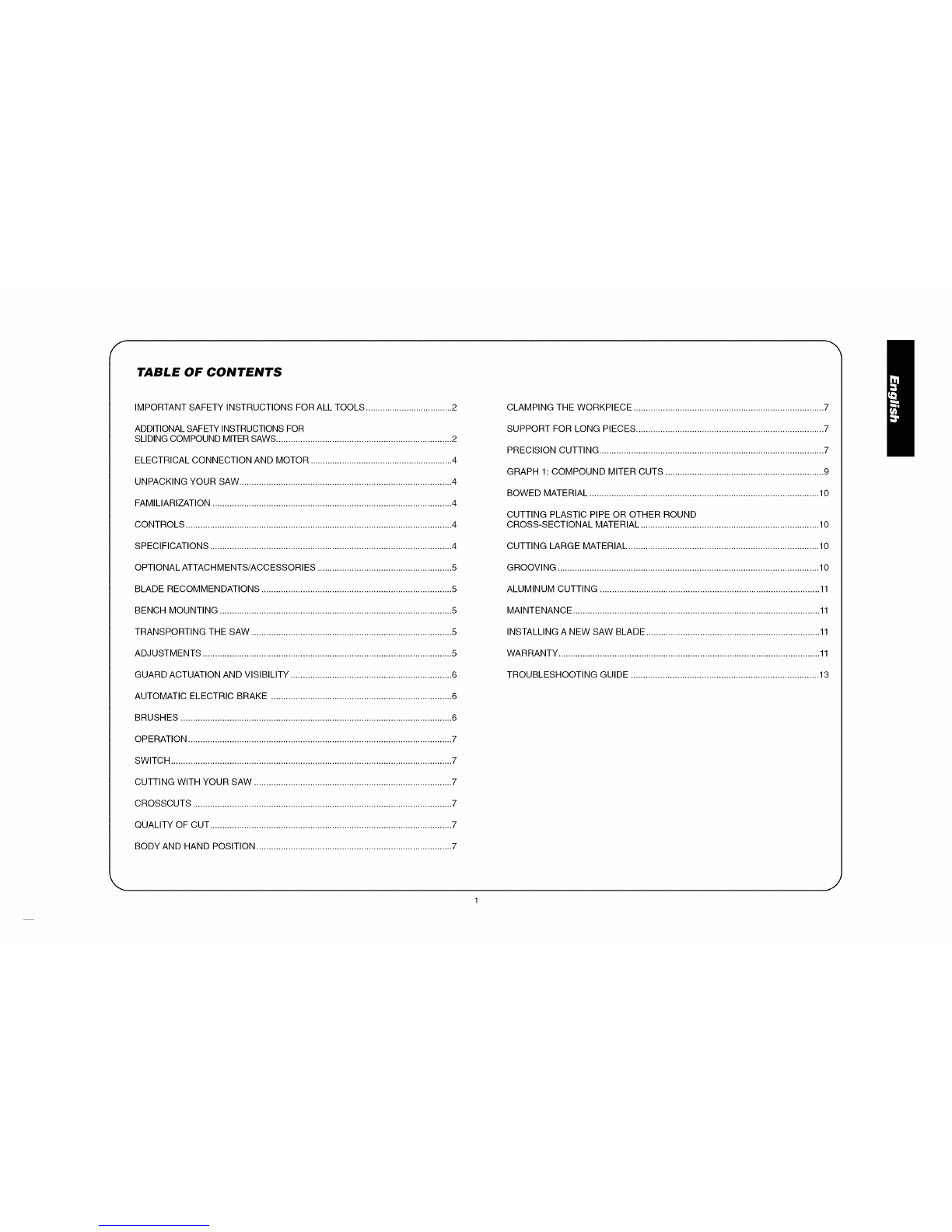
Adjusting the bevel stop to 45°left
NOTE: Adjust the 45 ° bevel
angles only after performing the 0°
bevel angle adjustment and bevel F
pointer adjustment.
To adjust the left 45° bevel angle,
loosen the bevel lock handle (F) and
tilt the head to the left. Ifthe pointer R1(45°)
does not indicate exactly 45°, turn
the bevel stop screw (R1) until the
pointer reads 45°.
Toadjust the crown stop (33.85°) bevel angle, loosen the bevel
lock handle. When the saw is on the stop, if the pointer does not
indicate exactly 33.85 °, turn the bevel stop screw (R2) until the
pointer indicates 33.85 °.
FENCE ADJUSTMENT
WARNING: Disconnect the saw from the power supply,
turn off the machine and allow the blade to come to a com-
plete stop before raising the arm and prior to cleaning the
blade area, removing debris in the path of the blade,
before servicing or adjusting tool. A moving blade can
cause serious injury.
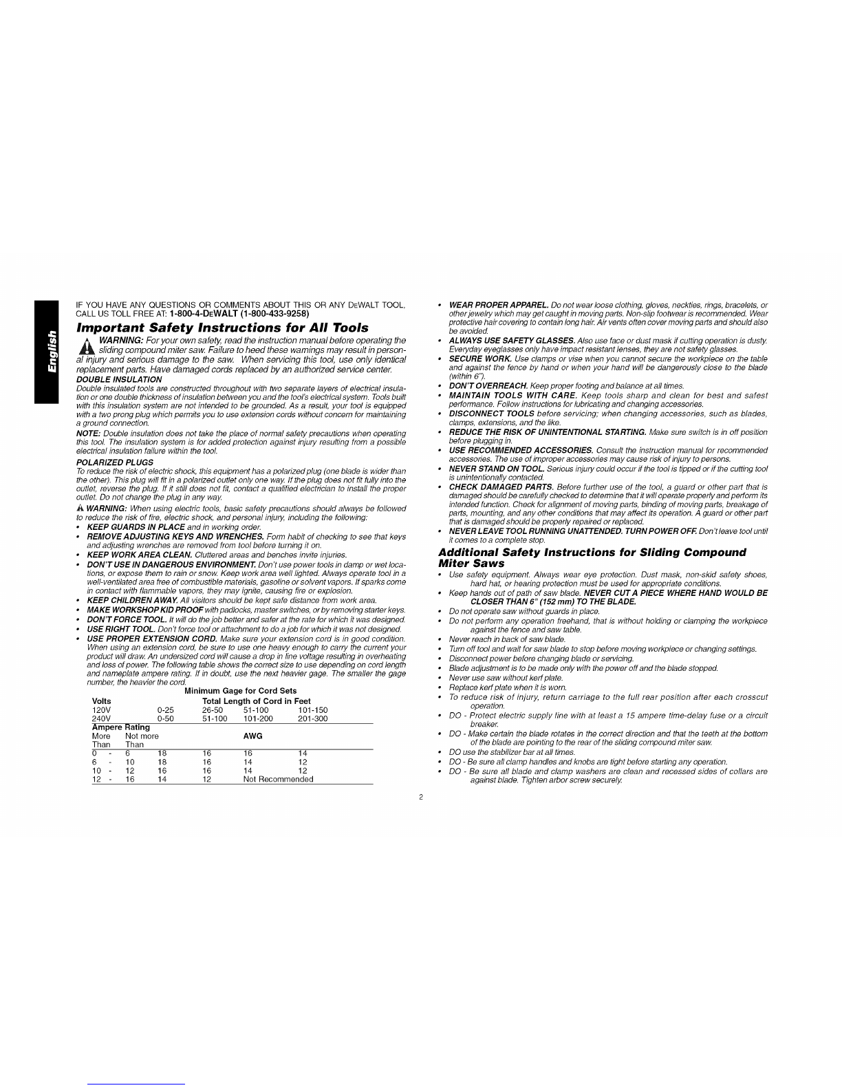
CAUTION: ALWAYS complete a dry K
run without power before making any \
cuts or damage to the fence may
OCCUi_
To Adjust the Sliding Fence
1. For normal use, loosen the knob
(K) one full turn to slide fence, then
tighten the knob securely. This will allow clearance
between the fence and the blade.
2. To provide maximum workpiece support when cutting
smaller pieces, loosen the knob (K) three full turns. The
fence will slide freely allowing the fence to move closer to
the blade. Tighten the knob securely.
NOTE: When beveling and mitering, it may, in rare circum-
stances, be necessary to remove the sliding fence. To remove
the fence, fully loosen the fence adjustment knob until the fence
is free to slide off. Reinstall the sliding fence and adjust properly
for workpiece support.
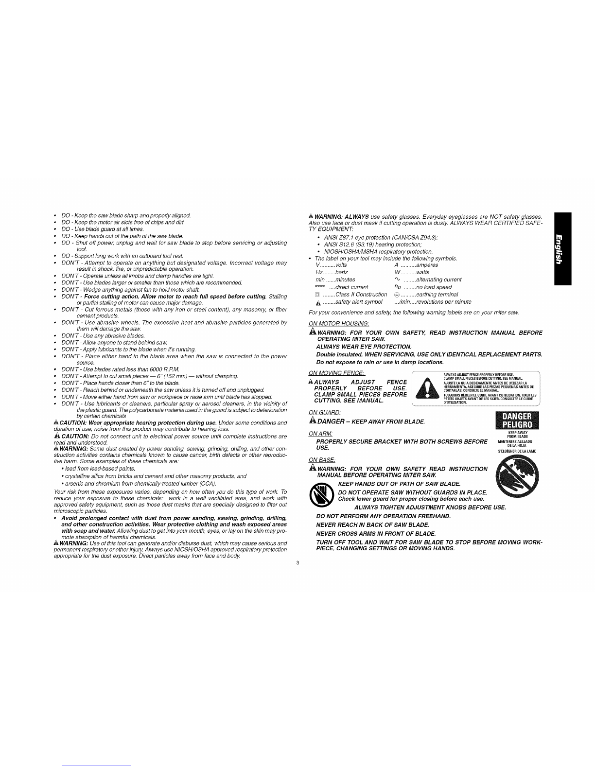
RAIL GUIDE ADJUSTMENT s H
Periodically check the rails for any \
play or clearance. The right rail
can be adjusted with the set
screw (S) shown on top of the
support housing. To reduce clear-
ance, rotate the set screw clock-
wise gradually while sliding the
saw head back and forth. Reduce
play while maintaining minimum
sliding force.
NOTE: The rail lock knob (H) must be loose to allow the saw
rails to slide.
KERF PLATE ADJUSTMENT
AWARNING: Disconnect the saw from
the power supply, turn off the machine
and allow the blade to come to a com-
plete stop before raising the arm and
prior to cleaning the blade area, remov-
ing debris in the path of the blade,
before servicing or adjusting tool A
moving blade can cause serious injury.
Do not use this saw without a kerf plate
installed. Replace a kerf plate when ff is worn or damaged.
To install anew kerr plate:
1. Remove the three screws holding each kerf plate in place.
2. Remove the ken<plates and clean the area beneath.
3. Install the new kerf plates.
4. Replace the screws.
To adjust the kerf plate for the desired blade:
1. Loosen but do not remove the three kerf plate screws.
2. Adjust the plates to fit closely to the teeth of the blade.
3. Tighten the 3 screws on each kerf plate.
Guard Actuation and Visibility
The blade guard on your saw
has been designed to automatically
raise when the arm is brought down
and to lower over the blade when the
arm is raised.
The guard can be raised by hand
when installing or removing saw
blades or for inspection of the saw.
NEVER RAISE THE BLADE GUARD
MANUALLY UNLESS THE SAW IS
TURNED OFR UNPLUG THE SAW BEFORE ANY CLEANING
OR ADJUSTMENTS. If the guard becomes dirty, clean with a
dry cloth or a water-dampened cloth.
ACAUTION: Do not use lubricants or cleaners, particularly
spray or aerosol cleaners, in the vicinity of the plastic guard. The
polycarbonate material used in the guard is subject to
deterioration by certain chemicals.
NOTE: Certain special cuts will require that you manually raise
the guard. See the section titled Cutting Large Material on
page 10.
The front section of the guard is Iouvered for visibility while
cutting. Although the louvers dramatically reduce flying
debris, they are openings in the guard and safety glasses
should be worn at all times when viewing through the louvers.
Automatic Electric Brake
Your saw is equipped with an automatic electric blade brake
which stops the saw blade within 5 seconds of trigger release.
This brake is not adjustable.
On occasion, there may be a delay between the trigger releas-
ing and brake engagement. On rare occasions, the brake may
not engage at all and the blade will coast to a stop.
If a delay or "skipping" occurs, turn the saw on and off 4 or 5
times. If the condition persists, have the tool serviced by an
authorized DEWALT service center or other qualified personnel.
Always be sure the blade has stopped before removing it from
the kerr. The brake is not a substitute for guards or for ensur-
ing your own safety by giving the saw your complete attention.
Brushes
WARNING: Disconnect the saw from the power supply,
turn off the machine and allow the blade to come to a com-
plete stop before raising the arm and prior to cleaning the
blade area, removing debris in the path of the blade,
before servicing or adjusting tool A moving blade can
cause serious injury,
Inspect carbon brushes regularly
by unplugging tool, removing the
motor end cap, lift the brush spring
and withdraw the brush assembly.
Keep brushes clean and sliding
freely in their guides. Always
replace a used brush in the same
orientation in the holder as it was
prior to its removal. Carbon brushes have varying symbols
stamped into their sides, and if the brush is worn down to
approximately 1/2 inch, the spring will no longer exert pres-
sure and brushes must be replaced. Use only identical
DEWALT brushes. Use of the correct grade of brush is essen-
tial for proper operation of electric brake. New brush assem-
blies are available at DEWALT service centers. The tool
should be allowed to "run in" (run at no load) for 10 minutes
before use to seat new brushes. The electric brake may be
erratic in operation until the brushes are properly seated
(worn in). Always replace the motor end cap after inspecting
or servicing the brushes.
While "running in" DO NOT TIE, TAPE, OR OTHERWISE
LOCK THE TRIGGER SWITCH ON. HOLD BY HAND ONLY.
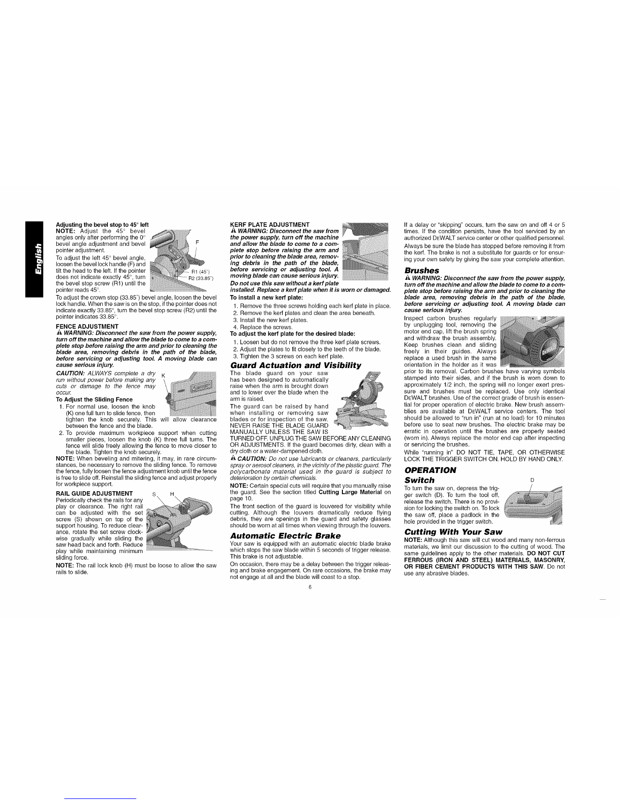
OPERATION
Switch
To turn the saw on, depress the trig-
ger switch (D). To turn the tool off,
release the switch. There is no provi-
sion for locking the switch on. To lock
the saw off, place a padlock in the
hole provided in the trigger switch.
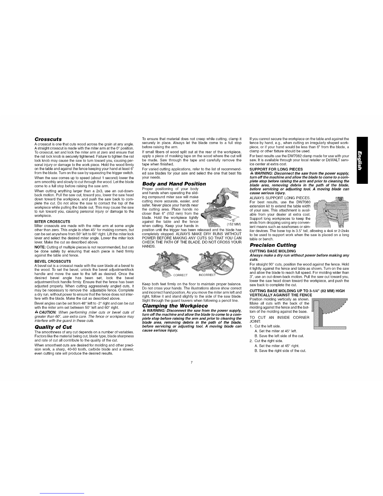
Cutting With Your Saw
NOTE: Although this saw will cut wood and many non-ferrous
materials, we limit our discussion to the cutting of wood. The
same guidelines apply to the other materials. DO NOT CUT
FERROUS (IRON AND STEEL) MATERIALS, MASONRY,
OR FIBER CEMENT PRODUCTS WITH THIS SAW. Do not
use any abrasive blades.

Crosscuts
A crosscut is one that cuts wood across the grain at any angle.
A straight crosscut is made with the miter arm at the 0° position.
To crosscut, set and lock the miter arm at zero and ensure that
the rail lock knob is securely tightened. Failure to tighten the rail
lock knob may cause the saw to turn toward you, causing per-
sonal injury or damage to the work piece. Hold the wood firmly
on the table and against the fence keeping your hand at least 6"
from the blade. Turn on the saw by squeezing the trigger switch.
When the saw comes up to speed (about 1 second) lower the
arm smoothly and slowly to cut through the wood. Let the blade
come to a full stop before raising the saw arm.
When cutting anything larger than a 2x3, use an out-down-
back motion. Pull the saw out, toward you, lower the saw head
down toward the workpiece, and push the saw back to com-
plete the cut. Do not allow the saw to contact the top of the
workpiece while pulling the blade out. This may cause the saw
to run toward you, causing personal injury or damage to the
workpiece.
MITER CROSSCUTS
Miter crosscuts are made with the miter arm at some angle
other than zero. This angle is often 45° for making corners, but
can be set anywhere from 50° left to 60° right. Lift the miter lock
lever and select the desired miter angle. Lower the miter lock
lever. Make the cut as described above.
NOTE: Cutting of multiple pieces is not recommended, but can
be done safely by ensuring that each piece is held firmly
against the table and fence.
BEVEL CROSSCUTS
A bevel cut is a crosscut made with the saw blade at a bevel to
the wood. To set the bevel, unlock the bevel adjustment/lock
handle and move the saw to the left as desired. Once the
desired bevel angle has been set, lock the bevel
adjustment/lock handle firmly. Ensure that the fence has been
adjusted properly. When cutting aggressively angled cuts, it
may be necessary to remove the adjustable fence. Complete
a dry run, without power to ensure that the fence does not inter-
fere with the blade. Make the cut as described above.
Bevel angles can be set from 48° left to -2° right and can be cut
with the miter arm set between 50° left and 60° right.
ACAUTION. When performing miter cuts or bevel cuts of
greater than 60 °, use extra care. The fence or workpiece may
interfere with the guard in these cuts.
Quality of Cut
The smoothness of any cut depends on a number of variables.
Factors like the material being cut, blade type, blade sharpness
and rate of cut all contribute to the quality of the cut.
When smoothest cuts are desired for molding and other preci-
sion work, a sharp, 40-60 tooth, carbide blade and a slower,
even cutting rate will produce the desired results.
To ensure that material does not creep while cutting, clamp it
securely in place. Always let the blade come to a full stop
before raising the arm.
If small fibers of wood split out at the rear of the workpiece,
apply a piece of masking tape on the wood where the cut will
be made. Saw through the tape and carefully remove the
tape when finished.
For varied cutting applications, refer to the list of recommend-
ed saw blades for your saw and select the one that best fits
your needs.
Body and Hand Position
Proper positioning of your body
and hands when operating the slid-
ing compound miter saw will make
cutting more accurate, easier, and
safer. Never place your hands near
the cutting area. Place hands no
closer than 6" (152 ram) from the
blade. Hold the workpiece tightly
against the table and the fence
when cutting. Keep your hands in (152 MM)
position until the trigger has been released and the blade has
completely stopped. ALWAYS MAKE DRY RUNS WITHOUT
POWER BEFORE MAKING ANY CUTS SO THAT YOU CAN
CHECK THE PATH OF THE BLADE. DO NOT CROSS YOUR
HANDS.
CORRECT INCORRECT
Keep both feet firmly on the floor to maintain proper balance.
Do not cross your hands. The illustrations above show correct
and incorrect hand position. As you move the miter arm left and
right, follow it and stand slightly to the side of the saw blade.
Sight through the guard louvers when following a pencil line.
Clamping the Workpiece
_k WARNING: Disconnect the saw from the power supply,
turn off the machine and allow the blade to come to a com-
plete stop before raising the arm and prior to cleaning the
blade area, removing debris in the path of the blade,
before servicing or adjusting tool A moving blade can
cause serious injury.
If you cannot secure the workpiece on the table and against the
fence by hand, e.g., when cutting an irregularly shaped work-
piece, or if your hand would be less than 6" from the blade, a
clamp or other fixture should be used.
For best results use the DW7082 clamp made for use with your
saw. It is available through your local retailer or DEWALT serv-
ice center at extra cost.
SUPPORT FOR LONG PIECES
AWARNING: Disconnect the saw from the power supply,
turn off the machine and allow the blade to come to a com-
plete stop before raising the arm and prior to cleaning the
blade area, removing debris in the path of the blade,
before servicing or adjusting tool A moving blade can
cause serious injury.
ALWAYS SUPPORT LONG PIECES.
For best results, use the DW7080
extension kit to extend the table width
of your saw. This attachment is avail-
able from your dealer at extra cost.
Support long workpieces to keep the
ends from dropping using any conven-
ient means such as sawhorses or sim-
ilar devices. The base top is 3.5" tall, allowing a 4x4 or 2-2x4s
to be used to support work when the saw is placed on a long
table or bench.
Precision Cutting
CUTTING BASE MOLDING
Always make a dry run without power before making any
cuts,
For straight 90° cuts, position the wood against the fence. Hold
it tightly against the fence and table as shown. Turn on the saw
and allow the blade to reach full speed. For molding wider than
3", use an out-down-back motion. Pull the saw out toward you,
lower the saw head down toward the workpiece, and push the
saw back to complete the cut.
CUTTING BASE MOLDING UP TO 3-1/4" (82 MM) HIGH
VERTICALLY AGAINST THE FENCE
Position molding vertically as shown.
Make all cuts with the back of the
molding against the fence and the bot-
tom of the molding against the base.
TO CUT AN INSIDE CORNER
JOINT:
1. Cut the left side.
A. Set the miter at 45° left.
B. Save the left side of the cut.
2. Cut the right side.
A. Set the miter at 45° right.
B. Save the right side of the cut.

TOCUTANOUTSIDECORNERJOINT:
1.Cuttheleftside.
A.Setthemiterat45°right.
B.Savetheleftsideofthecut.
2.Cuttherightside.
A.Setthemiterat45°left.
B.Savetherightsideofthecut.
Materialupto3-1/4"(82mm)canbecutasdescribedabove.
CUTTING BASE MOLDING USING THE BEVEL FEATURE
Make all cuts for 90° corner joints with the saw set at a 45°
bevel angle and a 0° miter angle.
TO MAKE AN INSIDE CORNER JOINT:
1. Cut the left side.
A. Position the molding with the
flat, narrow side against the
fence and the flat, broad side POSITIONA
against the saw table as
shown (position A).
B. Set the bevel at 45° left.
C. Save the left side of the cut.
2. Cut the right side.
A. Position the molding with the
curved, narrow edge against
the fence. The broad, flat side
of the molding should still be POSITION B
placed against the table of the
saw (position B).
B. Set the bevel at 45° left
C. Save the left side of the cut.
TO MAKE AN OUTSIDE CORNER JOINT:
1. Cut the left side.
A. Position the molding with the flat, narrow side against the
fence as shown (position A).
B. Set the bevel at 45° left.
C. Save the right side of cut.
2. Cut the right side.
A. Position the molding with the curved, narrow edge against
the fence (position B). The broad, flat side of the molding
should still be placed against the table of the saw.
B. Set the bevel at 45° left.
C. Save the right side of the cut.
CUTTING MOLDING RETURNS ...........
A "return" is cut to finish the end of a
chair rail or base molding. This piece is
a form of outside miter cut in which one
piece is very short. To make this cut,
place a piece of molding with a square
cut end into the saw. Set the miter
angle to 45° left. Slowly pull the blade MOL
through the molding, stopping before
the piece is cut through. Before stop- RETURN
ping the motor, lift the sawhead up
slightly and then release the trigger. This will leave the "return"
still connected to the molding by a small piece of wood.
Remove the wood from the saw and break the return from the
molding. This procedure prevents chipping of the small piece
of molding.
CUTTING CROWN MOLDING
Crown molding must be cut
with extreme accuracy to fit proper-
ly. On crown molding, the two flat
surfaces designed to fit against the
ceiling and the wall are cut in com-
plementary angles to the front of the
molding. Complementary angles,
when added together, equal exactly
90°. In most crown molding the sur-
face that fits flat against the ceiling and the back of the molding
form an angle of 52°. The bottom surface that fits flat against
the wall and the back of the molding form an angle of 38°.
Your sliding compound miter saw has pre-set miter stops at
31.6 ° left and right for cutting crown molding flat at the proper
angle to fit 90° inside and outside corners. There is also a mark
on the bevel scale at 33.85 °.
The inset box on page 10 gives the proper settings for cutting
crown molding with the flat, broad surface placed on the saw
table as shown. The angles for the miter and bevel settings are
very precise and are easy to accurately set on your saw by
using the pre-set stop settings.
CUTTING CROWN MOLDING ANGLED BETWEEN THE
FENCE AND TABLE (NESTED)
Place the molding on the table at an
angle between the fence and the saw
table, as shown. We recommend using
the crown molding fence accessory
(DW7084) because it affords accuracy
and convenience. The crown molding
fence accessory is available at extra cost
from your local dealer.
The advantage to cutting crown molding using the nested
method is that no bevel is required. Minute changes in the miter
angle can be made without adjusting the bevel angle. This way,
when cutting molding for unsquare corners, the saw can be
quickly and easily adjusted.
INSTRUCTIONS FOR CUTTING CROWN MOLDING
ANGLED BETWEEN THE FENCE AND SAW TABLE
1. Use the crown molding fence accessory to position the
molding at the angle at which it will be installed on the wall.
Position the molding so that the bottom (curved edge) of the
molding is against the fence and the top (pointed edge) of
the molding is resting on the base of the saw, as shown.
2. The angled "flats" on the back of the molding must rest
squarely on the fence and base of the saw.
TO MAKE AN INSIDE CORNER JOINT:
1. Cut the left side.
A. Set the miter at 45° right.
B. Save the right side of the cut.
2. Cut the right side.
A. Set the miter at 45° left
B. Save left side of the cut.
TO MAKE AN OUTSIDE CORNER JOINT:
1. Cut the left side.
A. Set the miter at 45° left.
B. Save the right side of the cut.
2. Cut the right side.
A. Set the miter at 45° right.
B. Save the left side of cut.
CUTTING PICTURE FRAMES, SHADOW BOXES AND
OTHER FOUR-SIDED PROJECTS
To best understand how to make the items listed here, we sug-
gest that you try a few simple projects using scrap wood until
you develop a feel for your saw.
Your saw is the perfect tool for mitering corners like the ones
shown below. Sketch A shows a joint made using the bevel
adjustment to bevel the edges of the two boards at 45° to pro-
duce a 90° corner. For this joint the miter arm is locked in the
zero position and the bevel adjustment is locked at 45°. The
wood is positioned with the broad flat side against the table and
the narrow edge against the fence. Alternatively, the cut could
be made by setting the bevel adjustment to the zero position
and setting the miter at 45°. In this case the wood is positioned
so that the broad, flat side is against the table and the narrow
side is against the fence.

GRAPH1:
COMPOUND
MITER CUTS
,<
o9
LU
T
N-
Z
0
LU
-J
Z
<
n"
UJ
N-
O9
.,,r
w
o9
45
40-
35-
30-'
25-
20-
15-
10-
5
0
10 15 20 25
• .5o" ,
_- ????7i???????????????????7i????
j:::::
15 20 25
SET THIS BEVELANGLE ON THE SAW
30 35 40 45
30 35 40 45
9

INSTRUCTIONS FOR CUTTING CROWN
MOLDING LAYING FLAT AND USING
THE COMPOUND FEATURES
1. Molding laying with broad back surface down flat
on saw table.
2. The settings below are for All Standard (U.S.)
crown molding with 52° and 38° angles.
BEVEL TYPE OF CUT
SETTING LEFT SIDE,INSIDE CORNER:
Left 33.85 ° 1. Top of molding against fence
2. Miter table set right 31.62 °
3. Save left end of cut
Flip your material so that the decorative edge is now
facing closest to the saw fence.
RIGHT SIDE, INSIDE CORNER:
Left 33.85 ° 1. Bottom of molding against
fence
2. Miter table set left 31.62 °
3. Save left end of cut
LEFT SIDE, OUTSIDE
CORNER:
Left 33.85 ° 1. Bottom of molding against
fence
2. Miter table set left 31.62 °
3. Save right end of cut
RIGHT SIDE, OUTSIDE
CORNER:
Left 33.85 ° 1. Top of molding against fence
2. Miter table set right 31.62 °
3. Save right end of cut
When setting bevel and miter angles for all com-
pound miters, remember that:
The angles presented for crown moldings are very
precise. Since they can easily shift slightly and very
few rooms have exactly square corners, all settings
should be tested on scrap molding.
PRETESTING WITH SCRAP MATERIAL IS
EXTREMELY IMPORTANT!
CUTTING TRIM MOLDING AND OTHER FRAMES
Sketch B shows a joint made by setting the miter adjustment at
45° and the bevel adjustment to the zero position. The wood is
positioned with the broad flat side on the table and the narrow
edge against the fence. Mitering the boards forms a 90 degree
corner.
The two sketches below are for four-sided objects only. As the
number of sides on a project changes, so do the miter and
bevel angles. The following chart gives the proper angles to
use when making frames in a variety of shapes.
SKETCH A SKETCH B
The chart assumes that all sides are of equal length. For a
shape that is not shown in the chart, use the following formula:
180° divided by the number of sides equals the miter or bevel
angle. - EXAMPLES -
NO. SIDES MITER OR BEVELANGLE
4 45°
5 36°
6 30°
7 25.7°
8 22.5°
9 20°
10 18°
CUTTING COMPOUND MITERS
A compound miter is a
cut made using a miter angle
and a bevel angle at the
same time. This is the type of
cut used to make frames or
boxes with slanting sides like
the one shown here.
The graph shown on page 9 will assist you in selecting the prop-
er bevel and miter settings for common compound miter cuts.
To use the graph, select the desired angle "A" of your project
and locate that angle on the appropriate arc in the chart. From
that point follow the chart straight down to find the correct bevel
angle and straight across to find the correct miter angle.
NOTE: If the cutting angle varies from cut to cut, check that
the bevel adjustment/lock handles and the miter adjustment-
/lock lever are securely tightened. These levers must be tight-
ened and locked after making any changes in the bevel or
miter settings.
Bowed Material
10
When cutting bowed material always position it as shown on
the right above and never like that shown on the left.
Positioning the material incorrectly will cause it to pinch the
blade near the completion of the cut.
Cutting Plastic Pipe or Other Round
Cross-Sectional Material
Plastic pipe and similar material
can be easily cut with your saw. It
should be cut just like wood. CLAMP
THE MATERIAL OR HOLD FIRMLY
TO PREVENT ROLLING ESPE-
CIALLY WHEN USING BEVEL OR
MITER FEATURES.
Cutting Large
Material
Occasionally you will encounter a
piece of wood a little too large to fit I
beneath the blade guard. A little extra
clearance can be gained by rolling the
guard up out of the way with your thumb
as shown. Rolling the guard in this man-
ner may also be necessary when making
certain compound cuts. Avoid doing this
as much as possible. However, the saw
will operate properly and make the deeper cut with the guard
rolled up. NEVER TIE, TAPE, OR OTHERWISE HOLD THE
GUARD OPEN WHEN OPERATING THIS SAW.
ACAUTION. Never raise the guard by hand except as
described above.
Grooving
Your sliding compound miter saw is equipped with a grooving
lever and thumbscrew and nut to allow for groove cutting. To
use the grooving feature, flip the grooving lever (I) toward the
front of the saw, as shown.
Loosen the nut and adjust J
the thumbscrew (J) to change
the depth of the groove cut. To
lock the thumbscrew in posi-
tion, retighten the nut.
ALWAYS MAKE DRY RUNS
WITHOUT POWER BEFORE
MAKING FINISH CUTS TO CHECK THE DEPTH OF THE
BLADE.
NOTE: Your saw is not designed for use with dado blades.
Aluminum Cutting
Never make any cut without firmly clamping material.
Certain workpieces, due to their size, shape, or surface finish,
may require the use of a clamp or fixture to prevent movement
during the cut.

Aluminumextrusionssuchasthoseusedwhenmakingalu-
minumscreensandstormwindowscaneasilybecutwithyour
saw.Positionthematerialsothatyouwillbecuttingthe
thinnestcrosssection,asshown.Theillustrationbelowshows
thewrongwaytocuttheseextrusions.Useastickwaxcutting
lubricantwhencuttingaluminum.Applythestickwaxdirectlyto
thesawbladebeforecutting.Neverapplystickwaxtoamov-
ingblade.Thewax,availableatmosthardwarestoresand
industrialmillsupplyhouses,providesproperlubricationand
keepschipsfromadheringtotheblade.
Besuretoproperlysecureworkpiece.Refertopage5for
informationaboutusingtheproperblade.
Maintenance
1. All bearings are sealed ball bearings. They are lubricated
for life and need no further maintenance. Do not use any
lubricant.
2. Periodically clean all dust and wood chips from around the
area of the saw blade inside the guard. Even though slots
are provided to allow debris to pass through, some dust will
accumulate.
CAUTION. Do not use lubricants or cleaners, particular
spray or aerosol cleaners, in the vicinity of the plastic guard.
The polycarbonate material used in the guard is subject to
deterioration by certain chemicals.
3. The brushes are designed to give you several years of use.
If they ever need replacement follow the instructions on
page 6 or return the tool to the nearest service center for
repair.
IMPORTANT SAFETY
INSTRUCTIONS
Changing or Installing a New Saw
Blade
CAUTION:
•Never depress the spindle lock button while the blade is
under power or coasting.
•De net cut ferrous metal (containing iron or steel) or
masonry or fiber cement product with this miter saw.
Removing the Blade
1. Unplug the saw.
2. Raise the arm to the upper position and raise the lower
guard (T) as far as possible.
3. Loosen, but do not remove guard bracket screw (U) until
the bracket can be raised far enough to access the blade
screw.
4. Depress the spindle lock button (E) while carefully rotating
the saw blade by hand until the lock engages.
5. Keeping the button depressed, use the other hand and the
wrench provided (V) to loosen the blade screw. (Turn
clockwise, left-hand threads)
6. Remove the blade screw (W), outer clamp washer (X), and
blade (Y). The inner clamp washer (Z), may be left on the
spindle.
REAR OF SAW
W X
Installing a Blade
1. Unplug the saw.
2. With the arm raised, the lower guard held open and the
pivot plate raised, place the blade on the spindle and
against the inner clamp washer with the teeth at the bottom
of the blade pointing toward the back of the saw.
3. Assemble the outer clamp washer onto the spindle.
4. Install the blade screw and, engaging the spindle lock,
tighten the screw firmly with wrench provided. (Turn coun-
terclockwise, left-hand threads)
5. Return the guard bracket to its original position and firmly
tighten the guard bracket screw to hold bracket in place.
AWARNING:
• The guard bracket must be returned to its
original position and the screw tightened
before activating the saw.
• Failure to do so may allow the guard to
contact the spinning saw blade resulting
in damage to the saw and severe per-
sonal injury.
Repairs
To assure product SAFETY and RELIABILITY, repairs, mainte-
nance and adjustment (including brush inspection and replace-
ment) should be performed by a DEWALT factory service cen-
ter, a DEWALT authorized service center or other qualified
service personnel. Always use identical replacement parts.
Three Year Limited Warranty
DEWALT will repair, without charge, any defects due to faulty
materials or workmanship for three years from the date of
purchase. This warranty does not cover part failure due to nor-
mal wear or tool abuse. For further detail of warranty coverage
and warranty repair information, visit www.dewalt.com or call
1-800-4-DEWALT (1-800-433-9258). This warranty does not
apply to accessories or damage caused where repairs have
been made or attempted by others. This warranty gives you
specific legal rights and you may have other rights which vary
in certain states or provinces.
In addition to the warranty, DEWALT tools are covered by our:
1 YEAR FREE SERVICE
DEWALT will maintain the tool and replace worn parts caused
by normal use, for free, any time during the first year after
purchase. 90 DAY MONEY BACK GUARANTEE
If you are not completely satisfied with the performance of your
DEWALT Power Tool, Laser, or Nailer for any reason, you can
return it within 90 days from the date of purchase with a receipt
for a full refund - no questions asked.
11

LATIN AMERICA: This warranty does not apply to products
sold in Latin America. For products sold in Latin America, see
country specific warranty information contained either in the
packaging, call the local company or see website for warranty
information.
FREE WARNING LABEL REPLACEMENT: If your warning
labels become illegible or are missing, call 1-800-4-DEWALT
for a free replacement.
12

Troubleshooting Guide
BE SURE TO FOLLOW SAFETY RULES AND INSTRUCTIONS
TROUBLE! Saw will not start
What's Wrong?
1. Saw not plugged in
2. Fuse blown or circuit breaker tripped
3. Cord damaged
4. Brushes worn out
What to do...
1. Plug in saw
2. Replace fuse or reset circuit breaker
3. Have cord replaced by authorized service center
4. Replace brushes (see page 6)
TROUBLE! Saw makes unsatisfactory cuts
What's Wrong?
1. Dull blade
2. Blade mounted backwards
3. Gum or pitch on blade
4. Incorrect blade for work being done
What to do...
1. Replace blade (see page 11)
2. Turn blade around (see page 11)
3. Remove blade and clean with turpentine and
coarse steel wool or household oven cleaner
4. Change the blade (see page 11)
TROUBLE! Blade does not come up to speed
What's Wrong?
1. Extension cord too light or too long
2. Low house current
What to do...
1. Replace with adequate sized cord (see page 2)
2. Contact your electric company
TROUBLE! Saw vibrates excessively
What's Wrong?
1. Saw not mounted securely to stand or work bench
2. Stand or bench on uneven floor
3. Damaged saw blade
What to do...
1. Tighten all mounting hardware (see page 5)
2. Reposition on flat level surface (see page 5)
3. Replace blade (see page 11)
TROUBLE! Saw makes inaccurate miter cuts
What's Wrong?
1. Miter scale not adjusted correctly
2. Blade is not square to fence
3. Blade is not perpendicular to table
4. Workpiece moving
What to do...
1. Check and adjust (see page 5)
2. Check and adjust (see page 5)
3. Check and adjust fence (see page 6)
4. Clamp workpiece to fence or glue 120 grit
sandpaper to fence with rubber cement
TROUBLE! Material pinches blade
What's Wrong?
1. Cutting bowed material
What to do...
1. Position bowed material as shown on page 10
13

fTABLE DES MATIERES
IMPORTANTES CONSIGNES DE SECURITC CONCERNANT
TOUS LES OUTILS .................................................................................................. 15
CONSIGNES DE SF:tCURITF:tADDITIONNELLES
CONCERNANT LES SCIES ,ikONGLETS COMBINEES ,ikCHARIOT .................... 16
RACCORDEMENT F:tLECTRIQUES ET MOTEUR ................................................ 17
DF:tBALLAGE DE LA SCIE .................................................................................... 17
FAMILIARISATION ................................................................................................ 17
COMMAN DES........................................................................................................ 17
CARACTF:tRISTIQUES TECHNIQUES ................................................................ 18
ACCESSOIRES OPTIONNELS ............................................................................ 18
DESCRIPTION DE LA LAME ........................................................................................ 18
MONTAGE SUR UN F:tTABLI................................................................................ 19
TRANSPORT DE LA SCIE .................................................................................... 19
RF:tGLAGES ............................................................................................................ 19
VISIBILITE ET DF:tCLENCHEMENT DU PROTEGE-LAME ................................ 20
FREIN F:tLECTRIQUE AUTOMATIQUE ................................................................ 20
BALAIS .................................................................................................................. 20
FONCTIONNEMENT ............................................................................................ 21
INTERRUPTEUR .................................................................................................. 21
METHODES DE COUPE ...................................................................................... 21
COUPES TRANSVERSALES .............................................................................. 21
QUALITE DE LA COUPE ...................................................................................... 21
POSITION DU CORPS ET DES MAINS .............................................................. 21
FIXATION DE LA PIECE ........................................................................................ 21
SUPPORT DE LONGUES PIECES .................................................................. 21
COUPES DE PRECISION .................................................................................... 22
PIECES COURBEES ............................................................................................ 23
GRAPHIQUE 1: COUPE EN ONGLETS MIXTES ................................................ 24
COUPE DE TUYAUX EN PLASTIQUE OU DE TOUT AUTRE
MATERIAU ARRONDI .......................................................................................... 25
COUPE DE GRANDE PIECES ............................................................................ 25
RAINURAGE .......................................................................................................... 25
COUPE DE L'ALUMINIUM .................................................................................... 25
ENTRETIEN .......................................................................................................... 25
INSTALLATION D'UNE NOUVELLE LAME .......................................................... 25
GARANTIE COMPLETE ........................................................................................ 26
GUIDE DE DEPANNAGE ...................................................................................... 27
14

SI VOUS AVEZ DES QUESTIONS OU VOUS VOULEZ NOUS FAIRE PART DE VOS COM-
MENTAIRES CONCERNANT CET OUTIL OU TOUT AUTRE OUTIL DEWALT, COMPOSEZ
SANS FRAIS LE : 1 800 433-9258
Importantes consignes de s_curit_ concernant tous les
outils
AAVERTISSEMENT: afin de travailler en toute securit6 et d'eviter les risques
de blessure ou d'endommager serieusement I'outil, lire attentivement le
guide d'utilisation avant d'utiliser la scie a onglets combinee a chariot. Lors
de I'entretien de I'outil, n'utiliser que des pieces de rechange identiques. On doit
faire remplacer les cordons endommages, y compris les rallonges, dans un centre
de service autorise.
DOUBLE ISOLATION
Afin de proteger I'utilisateur centre les chocs electriques, les outils _double isolation sent
completement recouverts de deux couches distinctes d'isolant electrique ou d'une double
epaisseur de matiere isolante. Les outils possedant ce type d'isolation ne sent pas destines
6tre mis _la terre et, par consequent, sent munis d'une fiche _deux broches permettant
d'utiliser une raflonge ne necessitant aucune prise de masse.
REMARQUE : le fait que cet outil soit muni d'une double isolation ne signifie pas que I'util-
isateur doit cesser de suivre les consignes de securit6 qui s'imposent, I'isolation offre une
protection supplementaire centre les blessures causees par un choc electrique Iorsque les
systemes d'isolation intemes font defaut.
FICHES POLARISEES
Afin de reduire les risques de choc electrique, cet outil est muni d'une fiche polarisee (c'est-
9-dire que I'une des lames est plus large que I'autre), et ne peut 6tre raccorde qu'9 une ral-
Ionge polarisee et ce, clans un seul sens. On doit I'inverser si on est incapable de I'enfoncer
completemenL Si la fiche ne s'adapte toujours pas, on doit demander _un electricien quali-
fie d'installer la prise appropriee. On ne doit jamais modifier la fiche.
_AVERTISSEMENT : Iorsqu'on utilise un outil electrique, on doit toujours suivre les con-
signes de securit6, y compris celles decrites ci-dessous, afin de r#duire les risques d'in-
cendie, de choc #lectrique et de blessure inclure le suivre :
•CARDER LES DISPOSITIFS DE PROTECTION EN PLACE et en ben #tat de fonction-
nement.
•RETIRER LES CLE-S DE RE-GLAGE, prendre I'habitude de s'assurer que les cl#s de
r#glage sent retir#es de I'outil avant de le d#marre_
• CARDER LA ZONE DE TRAVAIL PROPRE; les espaces de travail et les #tablis encom-
br#s sent propices aux accidents.
•UTILISERL'OUTILDANSDESENDROITSAPPROPRIE-S;nepasexposerI'outilglapluie
ou _la neige, ni I'utiliser dans des endroits humides ou mouill#s. Carder la zone de travail
bien #clair#e. Toujours utiliser I'outil darts un endroit bien a#r#, et jamais _proximit# de
matieres combustibles, de gaz ou de solvants; le moteur peut preduire des #tincefles
et enflammer des matieres environnantes, ce qui risque de causer un incendie ou une
explosion.
•TENIR LES ENFANTS A L'E-CART; s'assurer que personne ne s'approche de la zone de
travail.
•S'ASSURER QUE L'ATELIER EST SUR POUR LES ENFANTS; utiliser des cadenas, des
interrupteurs centraux ou enlever les commandes de d#marrage.
• NE PAS FORCER L'OUTIL; pour obtenir de meilleurs r#sultats et pr#venir les risques de
blessure, laisser I'outil couper _la vitesse pour laquefle il a #t# congu.
•UTILISER L'OUTIL APPROPRIE-; ne pas forcer I'outil ou I'accessoire, ni I'utiliser pour des
travaux autres que ceux pour lesquels il a#t# congu.
• UTILISER LES RALLONGES APPROPRIE-ES; s'assurer que la rallonge #lectrique est en
ben #tat et qu'efle est en mesure de porter le courant n#cessaire _I'outil. Une rallonge de
15
calibre inf#rieur entrafnera une chute de tension se traduisant par une perte de puissance
et une surchauffe. Le tableau ci-dessous illustre les calibres que Ibn doit utiliser selon la
Iongueur de la rallonge et I'intensit# nominale indiqu#e sur la plaque signal#tique. En cas de
doute, utiliser le calibre suivanL Plus le calibre est petit, plus la rallonge peut porter de
courant. Calibre minimal des cordons de rallonge
Longueur totale du cordon en meters
De 0 &7 De 7&15 De 15&30 De 30&45
De 0 &7 De7&15 De 15&39 De 30&45
Tension
120V
240V
Intensite (A)
Au Au
moins plus
0 6
6 10
10 - 12
12 - 16
Calibre moyen de fil
18 16 16 14
18 16 14 12
16 16 14 12
14 12 Non recommande
• PORTER DES VeL-TEMENTSAPPROPRIE-S; ne pas porter de v6tements amples ni de
gants, de cravate, de bague, de bracelet ou d'autres bijoux, car ceux-ci peuvent rester
coinc#s clans les pi#ces mobiles. On recommande le port de chaussures antid#rapantes.
Couvrir ou attacher les cheveux longs. Se tenir #loign# des #vents puisque ces derniers
pourraient camoufler des pieces mobiles.
• TOUJOURS PORTER DES LUNETTES DE SE-CURITE-; porter aussi un masque facial ou
un masque anti-poussieres Iorsqu'on souleve de la poussi#re. Les lunettes ordinaires
prot#gent uniquement les yeux centre les chocs et ne sent pas des lunettes de protection.
• IMMOBILISER LA PleL-CE;la retenir au moyen d'un #tau ou de but#es fixes s'il s'av#re
impossible de la fixer manuellement sur le plateau et centre le guide, ou si les mains risquent
de s'approcher de moins de 15 cm (6 po) de la lame.
• NE PAS TROP E-TENDRE LES BRAS; les pieds doivent rester ancr#s fermement au sol
afin de maintenir son #quilibre en tout temps.
• BIEN ENTRETENIR L'OUTIL; afin d'obtenir de meilleurs r#sultats et faire preuve de
prudence, garder I'outil propre et bien aiguis#. Suivre les consignes Iorsqu'on lubrifie ou
qu'on remplace les accessoires.
• DE-BRANCHER L'OUTIL avant de proc#der _I'entretien ou de remplacer des accessoires
comme les lames, les ferrures, les rallonges, etc.
•RE-DUIRE LES RISQUES DE DE-MARRAGEACCIDENTEL; s'assurer que I'interrupteur est
en position d'arr6t avant de brancher I'outil.
• UTILISER LES ACCESSOIRES RECOMMANDE-S; consulter le guide d'utilisation pour
savoir quels accessoires sent appropri#s. L'utilisation d'accessoires autres que ceux recom-
mand#s pourrait entrafner des blessures.
• NE JAMAIS METTRE LES PIEDS SUR L'OUTIL; si I'outil se renverse ou est accidentelle-
merit mis en marche, il pourrait entrMner des blessures graves.
• VE-RIFIER LES PIECES ENDOMMAGE-ES; avant de poursuivre les travaux, on doit exam-
iner attentivement les dispositifs de protection, ou toute autre piece endommag#e, afin de
s'assurer qu'ils fonctionnent toujours ad#quatement et qu'ils sent en mesure d'effectuer les
travaux pour lesquels ils ont #t# congus. V#rifier les pi#ces mobiles afin de s'assurer qu' elles
sent bien align#es et qu'elles ne restent pas coinc#es; v#rifier #galement les pieces et les
assemblages afin de s'assurer qu'il n'y a aucun bris ni aucune autre condition susceptible
de nuire au ben fonctionnement de I'outil. On doit faire r#parer ou remplacer toute piece
endommag#e, y compris les dispositifs de protection.
• NE JAMAIS LAISSER L'OUTIL FONCTIONNER SANS SURVEILLANCE; COUPER
L'ALIMENTATION E-LECTRIQUE et attendre que I'outil s'immobilise completement avant
de quitter les lieux.

Consignes de s_curit_ additionnelles concernant les
scies a onglets combin_es a chariot
•Toujours utiliser le materiel de securit6 approprie et porter des lunettes de protection. Utiliser
un masque anti-poussieres, des chaussures antid#rapantes, un casque de s6curit# et des
protecteurs auditifs Iorsque la situation le requiert.
•Garder los mains 61oignees du trajet de la lame. ON NE DOlT PAS COUPER DES PIECES
DE PETITE DIMENSION; ON DOlT TOUJOURS POUVOIR GARDER LES MAINS AAU
MOINS 152 mm (6 po) DE LA LAME.
•Ne pas faire fonctionner I'outil sans sos dispositifs de protection.
• hie pas utiliser Ibutil _main levee, c'est-9-dire sans retenir ou fixer la piece contre le guide
et le plateau.
• hie jamais mettre los mains derriere la lame.
•Arr6ter Ibutil et attendre que la lame s'immobilise completement avant de deplacer la piece
ou de modifier le reglage de Ibutil.
• Debrancher Ibutil avant de proceder _I'entretien ou de remplacer la lame.
•Couper le courant et attendre que la lame s'immobilise completement avant de proceder au
reglage de la lame.
• Nejamais utiliserlbutil sans la plaquette amovible.
• Remplacer la plaquette amovible Iorsqu'elle est usee.
•Afin de reduire los risques de blessure, repousser le chariot completement vers I'arri#re
apres chaque coupe transversale.
• ON DOlT proteger I'alimentation #lectrique au moyen d'un disjoncteur ou d'un fusible tem-
poris# de 15 amperes ou plus.
• ON DOlT s'assurer que la lame toume dans le bon sons et que los dents de la partie
inferieure pointent vers I'arriere de la scie _onglets combinee _chariot.
• ON NE DOlT PAS utiliser Ibutil sans la barre de stabilisation.
•ON NE DOlT PAS faire fonctionner Ibutil si los poignees de serrage et los boutons ne sont
pas bien serres.
• ON DOlT s'assurer que los rondelles de la lame et des brides de serrage sont propres et
que los parties en retra# des colliers sont bien appwees contre la lame. Bien serrer la vis
de I'arbre.
• ON DOlT maintenir la lame aiguisee et bien alignee.
• ON DOlT s'assurer que los entrees d'air du moteur sont exemptes de copeaux et de pous-
si#re.
• ON DOlT se servir des dispositifs de protection en tout temps.
• ON DOlT garder los mains eloign6es du trajet de la lame.
• ON DOlT couper le courant, debrancher Ibutil et attendre que la lame s'immobilise com-
pl#tement avant de proc#der _I'entretien ou au r#glage de Ibutil.
• ON DOlT assurer le support des Iongues pieces en allongeant la surface de travail.
• ON NE DOlT PAS faire fonctionner Ibutil sous une tension autre que cello indiquee afin
d'eviter los risques de choc electrique ou d'incendie ou le fonctionnement impr#visible de la
scie.
• ON NE DOlT PAS faire fonctionner Ibutil si los poignees de serrage ou los boutons ne sont
pas bien serres.
• ON NE DOlT PAS utiliser de lames dont los dimensions diff#rent de cellos recommandees.
• ON NE DOlT PAS placer quoi que ce soit contre le ventilateur de maniere _retenir I'arbre
du moteu_
• ON NE DOlT PAS forcer I'outil Iors de la coupe. On doit laisser ce dernier atteindre sa
vitesse maximale avant de proceder ala coupe afin d'eviter de caler le moteur, m6me
partiellement, et de causer ainsi des dommages importants.
• ON NE DOlT PAS couper des metaux ferreux (contenant du fer ou de I'acier), de la ma¢on-
nerie ou des materiaux en fibro-cimenL
16
• ON NE DOlT PAS utiliser de meule abrasive, car la chaleur excessive et los particules abra-
sives g6ner6es par celle-ci peuvent endommager la scie.
• ON NE DOlT PAS utiliser de lame abrasive.
• ON NE DOlT PAS permettre _qui que ce soit de se tenir derriere la scie.
• ON NE DOlT PAS lubrifier la lame Iorsqu'elle est en marche.
• ON NE DOlT PAS mettre los mains pros de la lame Iorsque la scie est branchee.
• ON NE DOlT PAS utiliser de lames ayant une vitesse nominale inferieure _6 000 tr/min.
• ON NE DOlT PAS couper des pieces de petite dimension (c'est-9-dire _au moins 152 mm
/ 6 po de la lame) sans los fixe_
•ON DOlT toujours garder los mains _au moins 152 mm (6 po) de la lame.
• ON NE DOlT PAS mettre los mains sous la scie ou derriere celle-ci Iorsqu'elle est en marche
ou branchee.
• ON NE DOlT PAS retirer los mains de la scie ou de la piece ni lever los bras avant que la
scie ne se soit completement arr6tee.
•ON NE DOlT PAS utiliser de lubrifiants ni de d#tergents (particulierement des produits pul-
v#ris6s ou en a#rosol) _proximit# du dispositif de protection en plastique; fabrique en poly-
carbonate, ce demier risque d'6tre gravement endommag# par certains produits chimiques.
AMISE EN GARDE .Porter un dispositif de protection personnel anti-bruit approprie
durant I'utilisation. Sous certaines conditions et pendant toute la duree de I'utilisation, le
bruit emanant de ce produit pourrait contribuer _la perte d'audition.
AMISE EN GARDE .Ne pas brancher I'outil _la prise electrique a vant d'avoir bien lu et com-
pris toutes les directives.
AAVERTISSEMENT . Certains outils electriques, tels que les sableuses, les scies, les
meules, les perceuses ou certains autres outils de construction, peuvent produire de la pous-
siere contenant des produits chimiques susceptibles d'entrafner le cancer, des malformations
congenitales ou pouvant 6tre nocifs pour le systeme reproductif. Parmi ces produits chim-
iques, on retrouve :
• le plomb dans les peintures _base de plomb,
• la silice cristalline dans les briques et le ciment et autres produits de ma_onnerie,
• I'arsenic et le chrome dans le bois de sciage ayant subi un traitement chimique (comme
I'arseniate de cuivre et de chrome).
Le risque associe _de telles expositions varie solon la frequence avec laquelle on effectue
cos travaux. Pour reduire I'exposition _de tels produits, il faut travailler dans un endroit bien
a6re et utiliser le materiel de s6curite approprie, tel un masque anti-poussieres specialement
congu pour filtrer los particules microscopiques.
•Eviter tout contact prolonge avec la poussiere soulevee par cot outil ou autres outils
electriques, porter des v#tements de protection et nettoyer los parties exposees du
corps avec de I'eau savonneuse. S'assurer de bien se proteger afin d'eviter d'absorber par
la bouche, les yeux ou la peau des produits chimiques nocifs.
_AVERTISSEMENT :Cet outil peut produire et repandre de la poussiere susceptible de
causer des dommages serieux et permanents au systeme respiratoire. Toujours utiliser un
appareil respiratoire anti-poussieres approuve par le NIOSH ou I'OSHA. Diriger les particules
dans le sens oppose du visage et du corps.
_&AVERTISSEMENT :TOUJOURS porter des lunettes de securite. Les lunettes de vue ne
constituent PAS des lunettes de securite. Utiliser egalement un masque facial ou anti-poussiere
si I'operation de decoupe g6n#re de la poussiere. TOUJOURS PORTER UN EQUIPEMENT DE
PROTECTION HOMOLOGUE :
• protection oculaire ANSI Z87.1 (CAN/CSA Z94.3),
• protection auditive ANSI $12.6 ($3.19) et
• protection des voies respiratoires NIOSH/OSHA.
• L'etiquette de I'outil peut comporter les symboles suivants.
V.................. volts A.................... amp#res
Hz ................ hertz W .................. watts

min.............. minutes _ ................ courant alternatif
.... ............ courant centinu no .................. sous vide
[] ................ Construction de classe II _ .................. beme de mise _la minute
................ symbole d'avertissement .../min ............ tours ou courses _la minute
Pour des fins pratiques et de securite, la scie _onglets comprend les etiquettes d'avertisse-
ment suivantes.
SUR LE CARTER DU MOTEUR ."
AVERTISSEMENT :AFIN DE TRAVAILLER EN TOUTE SECURITE, LIREATTENTIVE-
MENT LE GUIDE D'UTILISATION AVANT D'UTILISER LA SCIE.
TOUJOURS PORTER DES LUNETTES DE SECURITE.
OUTIL A DOUBLE ISOLATION. LORS DE L'ENTRETIEN, N'UTILISER QUE DES
PIECES DE RECHANGE IDENTIQUES.
NE PAS EXPOSER A LA PLUIE NI UTILISER DANS DES ENDROITS HUMIDES.
SUR LE GUIDE MOBILE ."
J_ TOUJOURS BIEN REGLER LE GUIDE '_WA_'A_'_STF"_€_"0P_"L_"E_0"E"SE.
AVANT D'UTILISER LA SCIE. FIXER _ _..',r"_._'A_E_O,E_,,'_,_._MAN,,L
AJUSTE LA GUJA DEBiDAMENTE ANTES DE UyJUZAR LA
SOLIDEMENT LES PIECES DE PETITES ,E,,A,i_,TA._SEGU,E_S_IEZ_SP_QU_,A_*,_SD_
CORTARLAS.CONSULTEEL MANUAL,
DIMENSIONS AVANT DE PROCEDER A LA ,o,_ou.,._._,,,_,,_A,',._u,_A,O,.,x_._s
PE3iTS 0BJETS AVANT DE LES SCIER. CONSULTE]_ LE GUIDE
COUPE. CONSULTER LE GUIDE D'UTILI- _......................................._uT!!P'!°"..................................................................................................
SATION.
SUR LE PROTE-GE-LAME ."
DANGER : SE TENIR LOIN DE LA LAME.
SUR LE BRAS ."
TOUJOURS SERRER FERMEMENT LA FERRURE AU MOYEN DES
DEUX VlS AVANT D'UTILISER L'OUTIL.
SUR LA BASE :
AAVERTISSEMENT : AFIN DE TRAVAILLER EN TOUTE SECURITE,
LIRE ATTENTIVEMENT LE GUIDE D'UTILISATION AVANT
D'UTILISER LA SCIE.
KEEP AWAY
FROM BLADE
MANTEi_ERS ALEJAD0
BE LA HOJA
S'EL0JGNER DE LA LAME
@
GARDER LES MAINS ELOIGNEES DU TRAJET DE LA LAME.
NE PAS FAIRE FONCTIONNER L'OUTIL SANS SES DISPOSITIFS DE
PROTECTION. VERIFIER LE PROTEGE-LAME INFERIEUR AFIN DE
S'ASSURER QU'IL SE REFERME CORRECTEMENT AVANT CHAQUE
UTILISA TION.
TOUJOURS SERRER SOLIDEMENT LES BOUTONS DE REGLAGE AVANT
D'UTILISER LA SCIE.
NE PAS UTILISER L'OUTIL A MAIN LEVEE.
NE JAMAIS EFFECTUER DE TRAVAUX A MAINS LEVEES.
NE JAMAIS METTRE LES MAINS DERRIERE L'OUTIL.
NE JAMAIS CROISER LES BRAS DEVANT LA LAME.
ARRETER L'OUTIL ET ATTENDRE QUE LA LAME S'IMMOBILISE COMPLETEMENT
AVANT DE DEPLACER LES MAINS OU LA PIECE OU DE MODIFIER LE REGLAGE
DE L'OUTIL.
DEBRANCHER L'OUTIL AVANT DE PROCEDER A L'ENTRETIEN OU DE CHANGER
UNE LAME.
AFIN DE REDUIRE LES RISQUES DE BLESSURE, REPOUSSER LE CHARIOT
COMPLETEMENT VERS L'ARRIERE APRES CHAQUE COUPE TRANSVERSALE.
REFLECHIR AFIN DE PREVENIR LES ACCIDENTS.
Raccordement dlectrique et moteur
S'assurer que I'alimentation correspond aux valeurs nominales inscrites sur la plaque signale-
tique de la scie, car I'interrupteur fera defaut si on utilise la scie en courant continu, comme darts
le cas d'une source de courant pour machine &souder. Utiliser une prise a courant alternatif
seulement afin d'eviter les risques de choc electrique ou d'incendie ou le fonctionnement
imprevisible de la scie. Une diminution de tension de 10% ou plus entrafnera une chute de puis-
sance et une surchauffe. Tousles outils de DEWALT sent mis & I'essai en usine. Si cet outil ne
fonctionne pas, verifier I'alimentation electrique.
De_ballage de la scie
La scie &onglets DW712 est completement assemblee avant d'6tre emballee. La bofte devrait
contenir :
1. une lame DEWALT & 30 dents de 216 mm (8 1/2 po) de diametre, installee sur la scie;
2. une cle de reglage de lame rangee dans le Iogement du capuchon d'extremite de la barre
transversale.
Familiarisation
La scie & onglets combinee & chariot est completement assemblee
au moment de sa livraison. Ouvrir la bofte et retirer lentement la scie
en la soulevant au moyen de la poignee et des barres transversales,
tel qu'illustre.
Deposer la scie sur une surface unie et plane, comme un etabli ou une
table solide.
Lire attentivement les directives et les consignes pour se familiariser
avec la scie et ses composantes. La section suivante sur les reglages
fait reference & ces termes; on dolt donc connaitre les pieces et leur
emplacement.
Appuyer legerement sur la poignee de manoeuvre et tirer sur la goupille
de verrouillage (A). Rel&cher doucement la pression ainsi exercee et laisser le
bras monter jusqu'& sa position maximale.
Commandes
La scie & onglets combinee a chariot comprend plusieurs commandes prin-
cipales decrites brievement aux presentes. Pour obtenir plus d'information
sur ces commandes, il suffit de consulter les sections decrites ci-dessous.
COMMANDE D'ONGLET
Le levier de verrouillage d'onglet (B) et le bouton de la detente (C)
permettent d'effectuer des coupes en onglet de 50-overs la gauche et
de 60-0vers la droite. Pour ce faire, soulever le levier de verrouillage
d'onglet, puis enfoncer le bouton de la detente et regler la scie &
I'angle voulu en se servant de I'echelle de reglage. Appuyer sur le
levier pour verrouiller le plateau. C
B
17

INTERRUPTEUR A GACHETTE
L'interrupteur & g&chette (D) permet de demarrer et d'arr6ter
I'outil; on peut actionner la g&chette soit de la main gauche,
soit de la main droite. La g&chette est munie d'un orifice dans
lequel on peut inserer un cadenas et ainsi bloquer la scie en
position d'arr6t.
POIGNC'E DE VERROUILLAGE D'ANGLE DE BISEAU
La poignee de verrouillage ou de
reglage d'angle de biseau (F) OUVREZ
permet d'effectuer des coupes en
biseau & 45-overs la gauche. Pour
desserrer la poignee et regler I'angle RURE
de biseau, tourner cette derniere
vers la gauche; la t_te de scie s'incline aisement vers la
gauche. Pour resserrer la poignee, la tourner vers la droite. Les
marques indiquant les angles de biseau sent situees sur le
cSte droit du bo_tier de soutien.
BOUTON DE SURPASSEMENT
DE LA BUT#E D'ANGLE
DE BISEAU
Le bouton de surpassement de la
butee d'angle de biseau (G) permet
d'effectuer des coupes en biseau au
del& des marques prer6gl6es 0-oet
45-0,jusqu'a concurrence de -2-0
48-0.La butee d'angle de biseau est regl6e en usine pour per-
mettre des coupes de moulures de couronnement de 33,85%
La scie s'arr6te automatiquement _.0-oet &45-0.Pour depasser
ces marques, tirer sur le bouton de surpassement et le toumer
jusqu'& la marque indiquant -2° ou 48°. Avant de I'utiliser, on
dolt incliner la scie vers la gauche par rapport a la position
zero. On peut egalement utiliser ce bouton pour regler la scie
en vue de realiser des coupes de moulures de couronnement
(33,85-0).
BOUTON DE VERROUILLAGE DES BARRES
TRANSVERSALES
Le bouton de verrouillage des barres
transversales (H) permet de bloquer la
t6te de la scie afin de I'emp6cher de
glisser. Tourner ensuite le bouton vers la
droite afin de bloquer la t6te (ou vers la
gauche, pour la liberer). La t6te dolt 6tre bloquee pour perme-
ttre d'effectuer certains reglages ou pour transporter la scie.
BUT#E DE RAINURAGE
La butee de rainurage permet les coupes en rainure. Basculer
le levier de rainurage (I) vers la partie avant de la scie, puis
utiliser la vis & oreilles (J) pour regler la profondeur de la coupe
en rainure (repousser le levier vers I'arriere si on n'utilise pas
cette fonction). Afin de couper une cannelure de profondeur
constante, mettez un bloc du bois au meins 50 mm (2 po) au
loin centre la barriere.
Autrement, la cannelure sera moins profond pres de a
barriere. Inverser le levier vers I'arriere de ra vu saute cette
caracteristique.
BOUTON DE REGLAGE DU GUIDE MOBILE
Le bouton de reglage du guide (K) K
permet de deplacer le guide de gauche.
Rel&cher le bouton de reglage en plas-
tique situe derriere le guide et faire glisser
ce dernier jusqu'a la positon voulue, soit
plus pres ou plus loin de la lame.
Resserrer le bouton de reglage avant d'u-
tiliser la scie.
Caract_ristiques techniques
CAPACIT# DE COUPE
Onglet : 50° a gauche et 60° _.droite
Biseau : entre -2° et 48° a gauche
ONGLET BISEAU LARGEUR HAUTEUR
MAXIMALE MAXIMALE
0° 0° 6,9 cm 30,0 cm
(2,7 po) (11,8 po)
48° (_tgauche, droite) 0° 6,9 cm 21,1 cm
(2,7 po) (8,3 po)
0° 45° 5,1 cm 30,0 cm
(a gauche) (2 po) (11,8 po)
REMARQUE : Iorsqu'on met une piece mince verticalement
centre le guide, la hauteur de coupe maximale augmente _.8,3
cm (3,25 po).
MC'CANISME D'ENTRAiNEMENT
Moteur de 120 volts
2 200 W
5 400 tr/min (fonctionnement a vide)
Engrenages helicofdaux avec coussinets & billes et &
galets
Lame au carbure a 30 dents
Frein electrique automatique
Accessoires optionnels
Les accessoires recommandes pour chaque outil sont vendus
separement aux centres de service de votre region. Pour
obtenir plus d'information sur les lames ou les accessoires,
communiquer avec DEWALT Industrial Tool Co., 701 East
Joppa Road, Baltimore, MD 21286 aux Etats-Unis;
composer le 1 (800) 4-DEWALT (1-800-433-9258) ou visiter
notre site Web www.dewalt.com.
18
AAVERTI$SEMENT : afin de travailler en toute s#curit#, I'u-
tilisateur dolt lire attentivement les directives de I'accessoire
concern#.
POSTE DE TRAVAIL DE LA SClE A ONGLET : DW723
Le poste de travail permet de regler rapidement et facilement
la position de la scie a onglet. Elle est munie d'un support de
piece et d'une butee.
RALLONGE DE PLATEAU DW7080
Congue pour supporter les pieces tres Iongues. La rallonge
requiert un assemblage; deux rallonges peuvent 6tre ajoutees
au plateau, soit une de chaque c6t&
BUT#E R#GLABLE DW7051
Congue pour 6tre utilisee avec un support de piece (voir la
description ci-dessus), la butee permet d'effectuer des coupes
multiples de m6me Iongueur (de 0 _.106 cm /0 a 42 po).
DISPOSITIF DE FIXATION DW7082
Permet de fixer solidement une piece au plateau afin d'ef-
fectuer une coupe plus precise.
GUIDE POUR MOULURES DE COURONNEMENT
DW7084
Permet d'effectuer avec precision la coupe de moulures de
couronnement.
SAC P,POUSSI#RE DW7053
Facile & vider gr&ce & la glissiere.
REMARQUE : le bec du sac est con£u pour en permettre le
raccord & I'embout d'un aspirateur, afin d'en vider le contenu.
Le sac dolt 6tre place correctement sans quoi il risque de nuire
au fonctionnement de la scie - le cas echeant, retirer le sac.
TOUJOURS EFFECTUER UN ESSAI, MOTEUR HeRS TEN-
SION, AVANT D'EFFECTUER UNE COUPE.
LAMES DE SClE : TOUJOURS UTILISER UNE LAME DE 216
mm (8 1/2 po). LA VITESSE DOlT Ft:TRE D'AU MOINS 6 000
tr/min. ON NE DOlT JAMAIS UTILISER UNE LAME DE
DIMENSION AUTRE QUE CELLE RECOMMANDE_E AFIN
D'FtVITER D'ENDOMMAGER SFtRIEUSEMENT LA SCIE.
MISE EN GARDE : I'utilisation de lames congues pour un
angle de coupe de plus de 5° (positif) et non dot#es d'un
m#canisme limiteur de profondeur risque de provoquer des
mouvements impr#vus de la scie vers I'avant.
Applications Description Nombre Type de
de la lame de dents coupe
Boiseries Lame de 40 a.60 Coupes tres
fines, precision, lisses, sans
moulures rainuree, au eclats
carhure
Boiseries, Lame 30 Coupes lisses
charpentes, combinee coupes rapides
traite sous
terrasses
Other manuals for DW712
7
Table of contents
Languages:
Other DeWalt Saw manuals

DeWalt
DeWalt D364-O4 User manual

DeWalt
DeWalt XR Li-Ion DCS380 User manual

DeWalt
DeWalt DW366 User manual

DeWalt
DeWalt DW788 User manual

DeWalt
DeWalt XRLi-ION DCS573 User manual

DeWalt
DeWalt DW744 User manual

DeWalt
DeWalt DW394 User manual

DeWalt
DeWalt DWE7499GD User manual

DeWalt
DeWalt DC351 User manual

DeWalt
DeWalt D28755 User manual

DeWalt
DeWalt DW713-XE User manual

DeWalt
DeWalt DCS727 User manual

DeWalt
DeWalt DCS373M2 User manual

DeWalt
DeWalt DW716 User manual

DeWalt
DeWalt DW390 User manual

DeWalt
DeWalt DW713 User manual

DeWalt
DeWalt DW310 User manual

DeWalt
DeWalt D28755 User manual

DeWalt
DeWalt DCS572NT-XJ User manual

DeWalt
DeWalt DW62 User manual