DeWalt DWS780 User manual

If you have questions or comments, contact us.
Pour toute question ou tout commentaire, nous contacter.
Si tiene dudas o comentarios, contáctenos.
1-800-4-DeWALT
Instruction Manual
Guide D’utilisation
Manual de instrucciones
Final Page Size: 8.5 x 11in
DWS780
12" (305 mm) Double Bevel Sliding Compound Miter Saw
Scie coulissante à onglet mixte 305 mm (12 po)
Sierra ingletadora compuesta deslizante de doble bisel de 305 mm (12")

B
ENGLISH
English (original instructions) 1
Français (traduction de la notice d’instructions originale) 14
Español (traducido de las instrucciones originales) 28

1
ENGLISH
English (original instructions)
Definitions: Safety Alert Symbols and Words
This instruction manual uses the following safety alert symbols and words to alert you to hazardous situations and your risk of personal injury or property damage.
DANGER: Indicates an imminently hazardous situation which, if not avoided, will result in death or seriousinjury.
WARNING: Indicates a potentially hazardous situation which, if not avoided, could result in death or seriousinjury.
CAUTION: Indicates a potentially hazardous situation which, if not avoided, may result in minor or moderateinjury.
(Used without word) Indicates a safety related message.
NOTICE: Indicates a practice not related to personal injury which, if not avoided, may result in propertydamage.
WARNING! Read all safety warnings and all
instructions. Failure to follow the warnings and
instructions may result in electric shock, fire and/or
seriousinjury.
WARNING: To reduce the risk of injury, read the
instructionmanual.
If you have any questions or comments about this or any
DeWALT tool, call us toll free at:
1-800-4-DeWALT (1-800-433-9258).
1 Trigger switch
2 Operating handle
3 Mounting holes
4 Lower guard
5 Miter lock handle
6 Miter latch button
7 Miter scale
8 Miter scale screws
9 Hand indentations
10 Fence
11 Bevel lock knob
12 Dust duct inlet
13 Lifting handle
14 Fence adjustment knob
15 Dust port
16 Table
17 Lock down pin
18 Base
19 XPS On/Off switch
20 Wing nut
21 Vertical material clamp
22 Miter latch override
23 Rails
24 Depth stop
25 Kerf plate
26 Miter pointer screw
27 0° bevel stop
28 Depth adjustment screw
29 Rail lock knob
30 Miter pointer
31 Rail set screw adjustment
32 Extension
Fig. A
5
6
22
26
28 20
24
30
8
1
14
9
10
18
19
32
11
27
17
2
13
23
14
7
12
5
4
10
21
25
16
3
9
15
29
31

2
ENGLISH
GENERAL POWER TOOL SAFETY WARNINGS
WARNING: Read all safety warnings, instructions, illustrations and specifications
provided with this power tool. Failure to follow all instructions listed below may result in
electric shock, fire and/or seriousinjury.
SAVE ALL WARNINGS AND INSTRUCTIONS FOR FUTURE
REFERENCE
The term “power tool” in the warnings refers to your mains-operated (corded) power tool or battery-
operated (cordless) powertool.
Work Area Safety
a ) Keep work area clean and well lit. Cluttered or dark areas inviteaccidents.
b ) Do not operate power tools in explosive atmospheres, such as in the presence of
flammable liquids, gases or dust. Power tools create sparks which may ignite the dust
orfumes.
c ) Keep children and bystanders away while operating a power tool. Distractions can
cause you to losecontrol.
Electrical Safety
d ) Power tool plugs must match the outlet. Never modify the plug in any way. Do not
use any adapter plugs with earthed (grounded) power tools. Unmodified plugs and
matching outlets will reduce risk of electricshock.
e ) Avoid body contact with earthed or grounded surfaces such as pipes, radiators,
ranges and refrigerators. There is an increased risk of electric shock if your body is earthed
orgrounded.
f ) Do not expose power tools to rain or wet conditions. Water entering a power tool will
increase the risk of electricshock.
g ) Do not abuse the cord. Never use the cord for carrying, pulling or unplugging the
power tool. Keep cord away from heat, oil, sharp edges or moving parts. Damaged
or entangled cords increase the risk of electricshock.
h ) When operating a power tool outdoors, use an extension cord suitable for outdoor
use. Use of a cord suitable for outdoor use reduces the risk of electricshock.
i ) If operating a power tool in a damp location is unavoidable, use a ground
fault circuit interrupter (GFCI) protected supply. Use of a GFCI reduces the risk of
electricshock.
Personal Safety
j ) Stay alert, watch what you are doing and use common sense when operating a
power tool. Do not use a power tool while you are tired or under the influence of
drugs, alcohol or medication. A moment of inattention while operating power tools may
result in serious personalinjury.
k ) Use personal protective equipment. Always wear eye protection. Protective
equipment such as dust mask, non-skid safety shoes, hard hat, or hearing protection used for
appropriate conditions will reduce personalinjuries.
l ) Prevent unintentional starting. Ensure the switch is in the off position before
connecting to power source and/or battery pack, picking up or carrying the tool.
Carrying power tools with your finger on the switch or energizing power tools that have the
switch on invitesaccidents.
m ) Remove any adjusting key or wrench before turning the power tool on. A wrench or a
key left attached to a rotating part of the power tool may result in personalinjury.
n ) Do not overreach. Keep proper footing and balance at all times. This enables better
control of the power tool in unexpectedsituations.
o ) Dress properly. Do not wear loose clothing or jewelry. Keep your hair, clothing and
gloves away from moving parts. Loose clothes, jewelry or long hair can be caught in
movingparts.
p ) If devices are provided for the connection of dust extraction and collection facilities,
ensure these are connected and properly used. Use of dust collection can reduce dust-
relatedhazards.
q ) Do not let familiarity gained from frequent use of tools allow you to become
complacent and ignore tool safety principles. A careless action can cause severe injury
within a fraction of asecond.
Power Tool Use and Care
r ) Do not force the power tool. Use the correct power tool for your application. The
correct power tool will do the job better and safer at the rate for which it wasdesigned.
s ) Do not use the power tool if the switch does not turn it on and off. Any power tool that
cannot be controlled with the switch is dangerous and must berepaired.
t ) Disconnect the plug from the power source and/or the battery pack from the power
tool before making any adjustments, changing accessories, or storing power tools.
Such preventive safety measures reduce the risk of starting the power toolaccidentally.
u ) Store idle power tools out of the reach of children and do not allow persons
unfamiliar with the power tool or these instructions to operate the power tool.
Power tools are dangerous in the hands of untrainedusers.
v ) Maintain power tools. Check for misalignment or binding of moving parts,
breakage of parts and any other condition that may affect the power tool’s
operation. If damaged, have the power tool repaired before use. Many accidents are
caused by poorly maintained powertools.
w ) Keep cutting tools sharp and clean. Properly maintained cutting tools with sharp cutting
edges are less likely to bind and are easier tocontrol.
x ) Use the power tool, accessories and tool bits, etc. in accordance with these
instructions, taking into account the working conditions and the work to be
performed. Use of the power tool for operations different from those intended could result
in a hazardoussituations.
y ) Keep handles and grasping surfaces dry, clean and free from oil and grease. Slippery
handles and grasping surfaces do not allow for safe handling and control of the tool in
unexpectedsituations.
Service
z ) Have your power tool serviced by a qualified repair person using only identical
replacement parts. This will ensure that the safety of the power tool ismaintained.
Safety Instructions for Miter Saws
a ) Miter saws are intended to cut wood or wood-like products, they cannot be used
with abrasive cut-off wheels for cutting ferrous material such as bars, rods, studs,
etc. Abrasive dust causes moving parts such as the lower guard to jam. Sparks from abrasive
cutting will burn the lower guard, the kerf insert and other plasticparts.
b ) Use clamps to support the workpiece whenever possible. If supporting the
workpiece by hand, you must always keep your hand at least 4" (100 mm) from
either side of the saw blade. Do not use this saw to cut pieces that are too small to
be securely clamped or held by hand. If your hand is placed too close to the saw blade,
there is an increased risk of injury from bladecontact.
c ) The workpiece must be stationary and clamped or held against both the fence and
the table. Do not feed the workpiece into the blade or cut “freehand” in any way.
Unrestrained or moving workpieces could be thrown at high speeds, causinginjury.
d ) Push the saw through the workpiece. Do not pull the saw through the workpiece. To
make a cut, raise the saw head and pull it out over the workpiece without cutting,
start the motor, press the saw head down and push the saw through the workpiece.
Cutting on the pull stroke is likely to cause the saw blade to climb on top of the workpiece
and violently throw the blade assembly towards theoperator.
e ) Never cross your hand over the intended line of cutting either in front or behind the
saw blade. Supporting the workpiece “cross handed” i.e. holding the workpiece to the right
of the saw blade with your left hand or vice versa is verydangerous.
f ) Do not reach behind the fence with either hand closer than 4" (100 mm) from
either side of the saw blade, to remove wood scraps, or for any other reason while
the blade is spinning. The proximity of the spinning saw blade to your hand may not be
obvious and you may be seriouslyinjured.
g ) Inspect your workpiece before cutting. If the workpiece is bowed or warped, clamp
it with the outside bowed face toward the fence. Always make certain that there
is no gap between the workpiece, fence and table along the line of the cut. Bent or
warped workpieces can twist or shift and may cause binding on the spinning saw
blade while cutting. There should be no nails or foreign objects in theworkpiece.
h ) Do not use the saw until the table is clear of all tools, wood scraps, etc., except
for the workpiece. Small debris or loose pieces of wood or other objects that contact the
revolving blade can be thrown with highspeed.
i ) Cut only one workpiece at a time. Stacked multiple workpieces cannot be adequately
clamped or braced and may bind on the blade or shift duringcutting.
j ) Ensure the miter saw is mounted or placed on a level, firm work surface before use.
A level and firm work surface reduces the risk of the miter saw becomingunstable.
k ) Plan your work. Every time you change the bevel or miter angle setting, make sure
the fence will not interfere with the blade or the guarding system. Without turning
the tool “ON” and with no workpiece on the table, move the saw blade through a complete
simulated cut to assure there will be no interference or danger of cutting thefence.
l ) Provide adequate support such as table extensions, saw horses, etc. for a workpiece
that is wider or longer than the table top. Workpieces longer or wider than the miter
saw table can tip if not securely supported. If the cut-off piece or workpiece tips, it can lift the
lower guard or be thrown by the spinningblade.
m ) Do not use another person as a substitute for a table extension or as additional
support. Unstable support for the workpiece can cause the blade to bind or the workpiece to
shift during the cutting operation pulling you and the helper into the spinningblade.
n ) The cut-off piece must not be jammed or pressed by any means against the
spinning saw blade. If confined, i.e. using length stops, the cut-off piece could get wedged
against the blade and thrownviolently.
o ) Always use a clamp or a fixture designed to properly support round material such
as rods or tubing. Rods have a tendency to roll while being cut, causing the blade to “bite”
and pull the work with your hand into theblade.
p ) Let the blade reach full speed before contacting the workpiece. This will reduce the risk
of the workpiece beingthrown.
q ) If the workpiece or blade becomes jammed, turn the miter saw off. Wait for all
moving parts to stop and disconnect the plug from the power source and/or remove
the battery pack. Then work to free the jammed material. Continued sawing with a
jammed workpiece could cause loss of control or damage to the mitersaw.

3
ENGLISH
r ) After finishing the cut, release the switch, hold the saw head down and wait for
the blade to stop before removing the cut-off piece. Reaching with your hand near the
coasting blade isdangerous.
s ) Hold the handle firmly when making an incomplete cut or when releasing the
switch before the saw head is completely in the down position. The braking action of
the saw may cause the saw head to be suddenly pulled downward, causing a risk ofinjury.
Additional Safety Rules for Miter Saws
WARNING: Do not allow familiarity (gained from frequent use of your saw) to replace
safety rules. Always remember that a careless fraction of a second is sufficient to inflict
severeinjury.
WARNING: Never modify the power tool or any part of it. Damage or personal injury
couldresult.
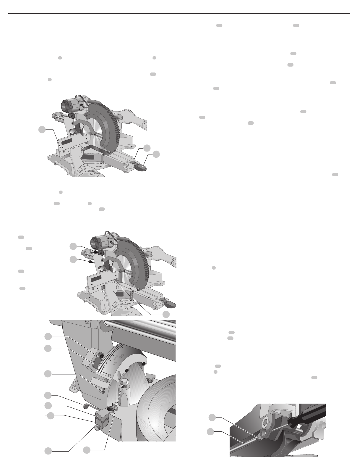
• DO NOT OPERATE THIS MACHINE until it is completely assembled and installed according to
the instructions. A machine incorrectly assembled can cause seriousinjury.
• OBTAIN ADVICE from your supervisor, instructor, or another qualified person if you are not
thoroughly familiar with the operation of this machine. Knowledge issafety.
• FOLLOW ALL WIRING CODES and recommended electrical connections to prevent shock
or electrocution. Protect electric supply line with at least a 15 ampere time-delay fuse or a
circuitbreaker.
• MAKE CERTAIN the blade rotates in the correct direction. The teeth on the blade should point in
the direction of rotation as marked on thesaw.
• TIGHTEN ALL CLAMP HANDLES, knobs and levers prior to operation. Loose clamps can cause
parts or the workpiece to be thrown at highspeeds.
• BE SURE all blade and blade clamps are clean, recessed sides of blade clamps are against blade
and arbor screw is tightened securely. Loose or improper blade clamping may result in damage
to the saw and possible personalinjury.
• DO NOT OPERATE ON ANYTHING OTHER THAN THE DESIGNATED VOLTAGE for the saw.
Overheating, damage to the tool and personal injury mayoccur.
• DO NOT WEDGE ANYTHING AGAINST THE FAN to hold the motor shaft. Damage to tool and
possible personal injury mayoccur.
• NEVER CUT FERROUS METALS or masonry. Either of these can cause the carbide tips to fly off
the blade at high speeds causing seriousinjury.
• NEVER PLACE HANDS CLOSER THAN 4" (100 mm) FROM THEBLADE.
• NEVER HAVE ANY PART OF YOUR BODY IN LINE WITH THE PATH OF THE SAW BLADE.
Personal injury willoccur.
• NEVER APPLY BLADE LUBRICANT TO A RUNNING BLADE. Applying lubricant could cause
your hand to move into the blade resulting in seriousinjury.
• DO NOT place either hand in the blade area when the saw is connected to the power source.
Inadvertent blade activation may result in seriousinjury.
• NEVER REACH AROUND OR BEHIND THE SAW BLADE. A blade can cause seriousinjury.
• DO NOT REACH UNDERNEATH THE SAW unless it is unplugged and turned off. Contact with
saw blade may cause personalinjury.
• SECURE THE MACHINE TO A STABLE SUPPORTING SURFACE. Vibration can possibly cause
the machine to slide, walk, or tip over, causing seriousinjury.
• USE ONLY CROSSCUT SAW BLADES recommended for miter saws. For best results, do not
use carbide tipped blades with hook angles in excess of 7 degrees. Do not use blades with deep
gullets. These can deflect and contact the guard, and can cause damage to the machine and/or
seriousinjury.
• USE ONLY BLADES OF THE CORRECT SIZE AND TYPE specified for this tool to prevent
damage to the machine and/or seriousinjury.
• INSPECT BLADE FOR CRACKS or other damage prior to operation. A cracked or damaged
blade can come apart and pieces can be thrown at high speeds, causing serious injury. Replace
cracked or damaged bladesimmediately.
• CLEAN THE BLADE AND BLADE CLAMPS prior to operation. Cleaning the blade and blade
clamps allows you to check for any damage to the blade or blade clamps. A cracked or damaged
blade or blade clamp can come apart and pieces can be thrown at high speeds, causing
seriousinjury.
• DO NOT USE WARPED BLADES. Check to see if the blade runs true and is free from vibration. A
vibrating blade can cause damage to the machine and/or seriousinjury.
• DO NOT use lubricants or cleaners (particularly spray or aerosol) in the vicinity of the plastic
guard. The polycarbonate material used in the guard is subject to attack by certainchemicals.
• KEEP GUARD IN PLACE and in workingorder.
• ALWAYS USE THE KERF PLATE AND REPLACE THIS PLATE WHEN DAMAGED. Small chip
accumulation under the saw may interfere with the saw blade or may cause instability of
workpiece whencutting.
• USE ONLY BLADE CLAMPS SPECIFIED FOR THIS TOOL to prevent damage to the machine
and/or seriousinjury.
• CLEAN THE MOTOR AIR SLOTS of chips and sawdust. Clogged motor air slots can cause the
machine to overheat, damaging the machine and possibly causing a short which could cause
seriousinjury.
• NEVER LOCK THE SWITCH IN THE “ON” POSITION. Severe personal injury mayresult.
• NEVER STAND ON TOOL. Serious injury could occur if the tool is tipped or if the cutting tool is
unintentionallycontacted.
• ADDITIONAL INFORMATION regarding the safe and proper operation of power tools (i.e., a
safety video) is available from the Power Tool Institute, 1300 Sumner Avenue, Cleveland, OH
44115-2851 (www.powertoolinstitute.com). Information is also available from the National
Safety Council, 1121 Spring Lake Drive, Itasca, IL 60143-3201. Please refer to the American
National Standards Institute ANSI 01.1 Safety Requirements for Woodworking Machines and the
U.S. Department of Labor OSHA 1910.213Regulations.
WARNING: Cutting plastics, sap coated wood, and other materials may cause melted
material to accumulate on the blade tips and the body of the saw blade, increasing the risk
of blade overheating and binding whilecutting.
WARNING: ALWAYS use safety glasses. Everyday eyeglasses are NOT safety glasses.
Also use face or dust mask if cutting operation is dusty. ALWAYS WEAR CERTIFIED
SAFETYEQUIPMENT:
• ANSI Z87.1 eye protection (CAN/CSA Z94.3),
• ANSI S12.6 (S3.19) hearing protection,
• NIOSH/OSHA/MSHA respiratoryprotection.
WARNING: Some dust created by power sanding, sawing, grinding, drilling, and other
construction activities contains chemicals known to the State of California to cause cancer,
birth defects or other reproductive harm. Some examples of these chemicalsare:
• lead from lead-based paints,
• crystalline silica from bricks and cement and other masonry products, and
• arsenic and chromium from chemically-treatedlumber.
Your risk from these exposures varies, depending on how often you do this type of work. To reduce
your exposure to these chemicals: work in a well ventilated area, and work with approved safety
equipment, such as those dust masks that are specially designed to filter out microscopicparticles.
• Avoid prolonged contact with dust from power sanding, sawing, grinding, drilling, and
other construction activities. Wear protective clothing and wash exposed areas with
soap and water. Allowing dust to get into your mouth, eyes, or lay on the skin may promote
absorption of harmfulchemicals.
WARNING: Use of this tool can generate and/or disperse dust, which may cause serious
and permanent respiratory or other injury. Always use NIOSH/OSHA approved respiratory
protection appropriate for the dust exposure. Direct particles away from face andbody.
WARNING: Always wear proper personal hearing protection that conforms to ANSI
S12.6 (S3.19) during use. Under some conditions and duration of use, noise from this
product may contribute to hearingloss.
• Air vents often cover moving parts and should be avoided. Loose clothes, jewelry or long
hair can be caught in movingparts.
• An extension cord must have adequate wire size (AWG or American Wire Gauge) for
safety. The smaller the gauge number of the wire, the greater the capacity of the cable, that is,
16 gauge has more capacity than 18 gauge. An undersized cord will cause a drop in line voltage
resulting in loss of power and overheating. When using more than one extension to make up
the total length, be sure each individual extension contains at least the minimum wire size. The
following table shows the correct size to use depending on cord length and nameplate ampere
rating. If in doubt, use the next heavier gauge. The lower the gauge number, the heavier thecord.
Minimum Gauge for Cord Sets
Volts Total Length of Cord in Feet
(meters)
120 V 25 (7.6) 50 (15.2) 100 (30.5) 150 (45.7)
240 V 50 (15.2) 100 (30.5) 200 (61.0) 300 (91.4)
Ampere Rating
American Wire Gauge
More
Than
Not
More
Than
0 6 18 16 16 14
610 18 16 14 12
10 12 16 16 14 12
12 16 14 12 Not Recommended
The label on your tool may include the following symbols. The symbols and their definitions are
asfollows:
V.........................volts
Hz .......................hertz
min.....................minutes
or DC......direct current
......................Class I Construction (grounded)
…/min..............per minute
BPM....................beats per minute
IPM.....................impacts per minute
RPM....................revolutions per minute
sfpm ...................surface feet per minute
SPM....................strokes per minute
A.........................amperes
W........................watts
or AC........... alternating current
or AC/DC....alternating or direct current
......................Class II Construction (double insulated)
no.......................no load speed
n.........................rated speed
......................earthing terminal
.....................safety alert symbol
.....................visible radiation
.....................wear respiratory protection
.....................wear eye protection
.....................wear hearing protection
.....................read all documentation
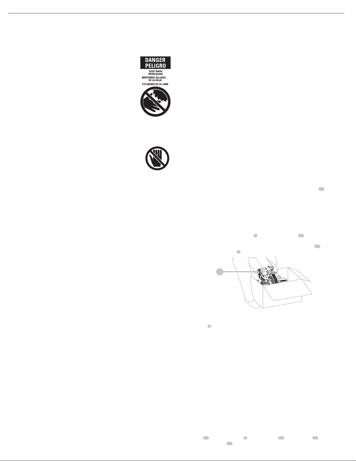
For your convenience and safety, the following warning labels are on your mitersaw.

4
ENGLISH
ON MOTOR ENDCAP:
TO REDUCE THE RISK OF INJURY, USER MUST READ INSTRUCTION MANUAL. WEAR EYE
PROTEXCTION AND RESPIRATORY PROTECTION. USE ONLY IDENTICAL REPLACEMENT PARTS.
DO NOT EXPOSE TO RAIN OR USE IN DAMPLOCATIONS.
ON FENCE:
ALWAYS ADJUST FENCE PROPERLY BEFORE USE. CLAMP SMALL PIECES BEFORE CUTTING.
SEEMANUAL.
ON GUARD:
DANGER–KEEP AWAY FROM BLADE.ON UPPER GUARD:
PROPERLY SECURE BRACKET WITH BOTH SCREWS BEFOREUSE.
ON TABLE: (2 PLACES)
WARNING: KEEP HANDS AND BODY OUT OF THE PATH OF THE
SAW BLADE. CONTACT WITH BLADE WILL RESULT IN SERIOUS
INJURY. DO NOT OPERATE SAW WITHOUT GUARDS IN PLACE.
CHECK GUARDING SYSTEM TO MAKE SURE IT IS FUNCTIONING
CORRECTLY. DO NOT PERFORM ANY OPERATION FREEHAND.
NEVER REACH IN BACK OF SAW BLADE TURN OFF TOOL AND
WAIT FOR SAW BLADE TO STOP BEFORE MOVING WORKPIECE OR CHANGING SETTINGS
OR MOVING HANDS. NEVER CROSS ARMS IN FRONT OF BLADE. ALWAYS TIGHTEN
ADJUSTMENT KNOBS BEFORE EACH USE. DISCONNECT POWER BEFORE CHANGING
BLADE ORSERVICING.
ON TABLE: (2 PLACES)
Double Insulation
Double insulated tools are constructed throughout with two separate layers of electrical
insulation or one single layer of reinforced insulation between you and the tool’s electrical
system. Tools built with this insulation system are not intended to be grounded. As a result,
your tool is equipped with a two prong plug which permits you to use extension cords without
concern for maintaining a groundconnection.
NOTE: Double insulation does not take the place of normal safety precautions when operating
this tool. The secondary insulation system is for protection against injury resulting from a possible
failure of the primary insulation within thetool.
CAUTION: WHEN SERVICING USE ONLY IDENTICAL REPLACEMENT PARTS. Repair or replace
damagedcords.
Polarized Plugs
Polarized plugs (one blade is wider than the other) are used on equipment to reduce the risk of
electric shock. When provided, this plug will fit in the polarized outlet only one way. If the plug
does not fit fully in the outlet, reverse the plug. If it still does not fit, contact a qualified electrician
to install the proper outlet. Do not change the plug in any way.
Electrical Connection
Be sure your power supply agrees with the nameplate marking. 120 volts, AC means that your
saw will operate on alternating current only. A voltage decrease of 10 percent or more will cause
a loss of power and overheating. All DeWALT tools are factory tested. If this tool does not operate,
check the powersupply.
Specifications
Capacity of cut
50° miter left and 60° miter right
49º bevel left and right
0° miter
Max. Height 4.4" (112 mm) Resulting Width 9.1" (231 mm)
Max. Width 13.75" (349 mm) Resulting Height 3.0" (76mm)
45° miter
Max. Height 4.4" (112 mm) Resulting Width 5.8" (147 mm)
Max. Width 9.6" (244 mm) Resulting Height 3.0" (76 mm)
45° bevel - Left
Max. Height 3.1" (79 mm) Resulting Width 11.4" (290 mm)
Max. Width 13.75" (349 mm) Resulting Height 1.7" (43 mm)
45º bevel - Right
Max. Height 2.2" (56 mm) Resulting Width 11.4" (290 mm)
Max. Width 13.75" (349 mm) Resulting Height 1.1" (28 mm)
Your saw is capable of cutting baseboard moldings 0.75" (19mm) thick by 6.5" (165mm) tall
on a 45° right or leftmiter.
Drive
120 Volt motor
15 Amp motor
3800 RPM
Cut helical gears
Multi-V belt
Carbide tooth blade
Automatic electric brake
Unpacking Your Saw
Check the contents of your miter saw carton to make sure that you have received all parts. In
addition to this instruction manual, the carton should contain:
1 DWS780 miter saw
1
DeWALT 12” (305 mm) diameter saw blade
In bag:
2 Base extensions
2 Extension clamps
2 Washers
2 Wing nuts
In bag:
1 Blade wrench
1 Material clamp
1 Instruction manual
Intended Use
This heavy duty miter saw is designed for professional wood cuttingapplications.
DO NOT use under wet conditions or in presence of flammable liquids orgases.
This miter saw is a professional power tool. DO NOT let children come into contact with the tool.
Supervision is required when inexperienced operators use thistool.
Familiarization (Fig. A, B)
Your miter saw is not fully assembled in the carton.Refer to the Assembly section for assembly
instructions. Open the box and lift the saw out by the convenient carrying handle13 , as shown
in FigureB.
Place the saw on a smooth, flat surface such as a workbench or strongtable.
Examine Figure A to become familiar with the saw and its various parts. The section on
adjustments will refer to these terms and you must know what and where the partsare.
CAUTION: Pinch Hazard. To reduce the risk of injury, keep thumb underneath the handle
when pulling the handle down. The lower guard will move up as the handle is pulled down
which could cause pinching.The handle is placed close to the guard for specialcuts.
Press down lightly on the operating handle2 and pull lock down pin17 . Gently release the
downward pressure and hold the arm allowing it to rise to its full height. Use the lock down pin
when carrying the saw from one place to another. Always use the lifting handle13 to transport
the saw or the hand indentations9 shown in FigureA.
Fig. B
13
Bench Mounting (Fig. A)
Mounting holes3 are provided in all 4 feet to facilitate bench mounting, as shown in FigureA.
(Two different-sized holes are provided to accommodate different sizes of screws. Use either
hole, it is not necessary to use both.) Always mount your saw firmly to a stable surface to prevent
movement. To enhance the tool’s portability, it can be mounted to a piece of 1/2” (12.7 mm) or
thicker plywood which can then be clamped to your work support or moved to other job sites
andreclamped.
NOTE: If you elect to mount your saw to a piece of plywood, make sure that the mounting
screws don’t protrude from the bottom of the wood. The plywood must sit flush on the work
support. When clamping the saw to any work surface, clamp only on the clamping bosses where
the mounting screw holes are located. Clamping at any other point will surely interfere with the
proper operation of thesaw.
CAUTION: To prevent binding and inaccuracy, be sure the mounting surface is not warped
or otherwise uneven. If the saw rocks on the surface place a thin piece of material under one
saw foot until the saw sits firmly on the mountingsurface.
Transporting the Saw (Fig. A)
WARNING: To reduce the risk of serious personal injury, turn off the tool and
disconnect it from the power source before attempting to move it, change
accessories or make anyadjustments.
WARNING: To reduce the risk of serious personal injury, always lock the rail lock
knob29, miter lock handle5 , bevel lock knob11, lock down pin17 and fence
adjustment knobs14 before transportingsaw.

5
ENGLISH
In order to conveniently carry the miter saw from place to place, a carrying handle13 has been
included on the top of the saw arm and hand indentations9 in the base, as shown in FigureA.
To transport the saw, lower the arm of the saw and press in the lock down pin17 to secure
thearm.
ASSEMBLY AND ADJUSTMENTS
WARNING: To reduce the risk of serious personal injury, turn unit off and disconnect
it from power source before making any adjustments or removing/installing
attachments or accessories. An accidental start-up can causeinjury.
NOTE: Your miter saw is fully and accurately adjusted at the factory at the time of manufacture.
If readjustment due to shipping and handling or any other reason is required, follow the steps
below to adjust yoursaw.
Once made, these adjustments should remain accurate. Take a little time now to follow these
directions carefully to maintain the accuracy of which your saw iscapable.
Assembling the Base Extensions (Fig. C1, C2)
WARNING: Base extensions must be assembled to both sides of the saw's base before using
the saw.
1. Locate the preassembled threaded stud54 underneath the saw’sbase.
2. The extension32 should be oriented as shown in Figure C2, sliding fully into the U-shaped
supports, ensuring the bolt 61 is between the clamp and the outer edge of the base.
3. Clamp the extension’s rods against the miter saw base by inserting the clamp55 over the
threaded stud 54, followed by the washer56 , and tightening the wing nut33 . Ensure the
extension is secure by pulling on the extension to verify no movement.
4. Repeat steps 1 through 3 on the other side.
32
Fig. C1
55
33
56
54
32
Fig. C2
54
55
61
Changing or Installing a New Saw Blade (Fig. A, D–F)
WARNING: To reduce the risk of serious personal injury, turn off the tool and
disconnect it from the power source before attempting to move it, change
accessories or make anyadjustments.
CAUTION:
• Never depress the spindle lock button while the blade is under power orcoasting.
• Do not cut ferrous metal (containing iron or steel) or masonry or fiber cement product
with this mitersaw.
Removing the Blade
1. Unplug thesaw.
2. Raise the arm to the upper position and raise the lower guard4 as far aspossible.
3. Loosen, but do not remove guard bracket screw58 until the bracket can be raised far
enough to access the blade screw34 . Lower guard will remain raised due to the position of
the guard bracketscrew.
4. Depress the spindle lock button35 while carefully rotating the saw blade by hand until the
lockengages.
5. Keeping the button depressed, use the other hand and the blade wrench36 provided to
loosen the blade screw. (Turn clockwise, left-hand threads.)
Fig. D
58
36
34
Fig. E 35
6. Remove the blade screw34 , outer blade clamp37 , and blade38 . The inner blade
clamp40 and if used, the 1" (25.4 mm) blade adapter, may be left on thespindle.
NOTE: For blades with a blade hole of 5/8" (15.88 mm), the 1" (25.4 mm) blade adapter 60
is notused.
Fig. F
34
37 38
40
60
Installing a Blade
1. Unplug thesaw.
2. With the arm raised, the lower guard held open and the guard bracket raised, place the blade
on the spindle, onto the blade adapter [if using a blade with a 1" (25.4 mm) diameter blade
hole] and against the inner blade clamp with the teeth at the bottom of the blade pointing
toward the back of thesaw.
3. Assemble the outer blade clamp onto thespindle.
4. Install the blade screw34 and, engaging the spindle lock, tighten the screw firmly with the
blade wrench provided. (Turn counterclockwise, left-hand threads.)
NOTE: When using blades with a 5/8" (15.88 mm) diameter blade hole, the blade adapter60
will not be used and should be stored in a safe place for futureuse.
5. Return the guard bracket to its original position and firmly tighten the guard bracket
screw58 to hold bracket inplace.

6
ENGLISH
WARNING:
• The guard bracket must be returned to its original position and the screw
tightened before activating thesaw.
• Failure to do so may allow the guard to contact the spinning saw blade resulting
in damage to the saw and severe personalinjury.
Miter Scale Adjustment (Fig. A, G)
Unlock the miter lock handle5 and swing the miter arm until the miter latch button6 locks it at
the 0° miter position. Do not lock the miter lock handle. Place a square against the saw’s fence and
blade, as shown. (Do not touch the tips of the blade teeth with the square. To do so will cause an
inaccurate measurement.) If the saw blade is not exactly perpendicular to the fence10 , loosen the
four miter scale screws8 that hold the miter scale and move the miter lock handle and the scale
left or right until the blade is perpendicular to the fence, as measured with the square. Retighten
the four screws. Pay no attention to the reading of the miter pointer at thistime.
Fig. G
6
10
5
Miter Pointer Adjustment (Fig. A)
Unlock the miter lock handle5 to move the miter arm to the zero position. With the miter lock
handle unlocked, allow the miter latch to snap into place as you rotate the miter arm to zero.
Observe the miter pointer30 and miter scale7 shown in FigureA. If the pointer does not
indicate exactly zero, loosen the miter pointer screw26 holding the pointer in place, reposition
the pointer and tighten thescrew.
Bevel Square to Table (Fig. A, H, I)
To align the blade square to the
table16 , lock the arm in the
down position with the lock
down pin17 . Place a square
against the blade, ensuring
the square is not on top of a
tooth. Loosen the bevel lock
knob 11 and ensure the arm is
firmly against the 0° bevel stop.
Rotate the 0° bevel adjustment
screw41 with the 1/2” blade
wrench as necessary so that the
blade is at 0° bevel to thetable.
Fig. I
41
42
43
45
44
46
49
50
11
17
16
Fig. H
Bevel Pointer (Fig. I)
If the bevel pointer42 does not indicate zero, loosen the screw43 that holds it in place and
move the pointer as necessary. Ensure the 0° bevel is correct and the bevel pointers are set before
adjusting any other bevel anglescrews.
Adjusting the Bevel Stop to 45° Left or Right (Fig. A, I)
To adjust the right 45° bevel angle, loosen the bevel lock knob11 and pull the 0° bevel stop
to override the 0° bevel stop. When the saw is fully to the right, if the bevel pointer does not
indicate exactly 45°, turn the left 45° bevel adjustment screw44 with the 1/2” blade wrench
until the bevel pointer indicates 45°.
To adjust the left 45° bevel stop, first loosen the bevel lock knob and tilt the head to the left. If the
bevel pointer does not indicate exactly 45°, turn the right 45° bevel adjustment screw44 until
the bevel pointer42 reads 45°.
Adjusting the Bevel Stop to 22.5° (or 33.9°) (Fig. A, I)
NOTE: Adjust the bevel angles only after performing the 0° bevel angle and bevel pointeradjustment.
• To set the left 22.5° bevel angle, flip out the left 22.5° bevel pawl46 . Loosen the bevel lock
knob11 and tilt the head fully to the left. If the bevel pointer does not indicate exactly 22.5°,
turn the crown adjustment screw45 contacting the pawl with a 7/16” wrench until the
bevel pointer reads 22.5°.
• To adjust the right 22.5° bevel angle, flip out the right 22.5° bevel pawl. Loosen the bevel lock
knob and pull the 0° bevel stop to override the 0° bevel stop. When the saw is fully to the
right, if the bevel pointer does not indicate exactly 22.5°, turn the crown adjustment screw
contacting the pawl with a 7/16” wrench until the bevel pointer indicates exactly22.5°.
Fence Adjustment (Fig. A)
In order that the saw can bevel to many bevel positions, one of the fences may have to be
adjusted to provide clearance. To adjust each fence, loosen the fence adjustment knob14
and slide the fence outward. Make a dry run with the saw turned off and check for clearance.
Adjust the fence to be as close to the blade as practical to provide maximum workpiece support,
without interfering with arm up and down movement. Tighten the fence adjustment knob
securely. When the bevel operations are complete, don’t forget to relocate thefence.
For certain cuts, it may be desirable to bring the fences closer to the blade. To use this feature,
back the fence adjustment knobs out two turns and move the fences closer to the blade past the
normal limit, then tighten the fence adjustment knobs to keep the fences in this location. When
using this feature, make a dry cut first to ensure the blade does not contact thefences.
NOTE: The tracks of the fences can become clogged with sawdust. If you notice that they are
becoming clogged, use a brush or some low pressure air to clear the guidegrooves.
Guard Actuation and Visibility (Fig. A, Z)
CAUTION: Pinch Hazard. To reduce the risk of injury, keep thumb underneath the handle
when pulling the handle down. The lower guard will move up as the handle is pulled down
which could causepinching.
The lower guard4 on your saw has been designed to automatically uncover the blade when the
arm is brought down and to cover the blade when the arm israised.
The guard can be raised by hand when installing or removing saw blades or for inspection of the
saw. NEVER RAISE THE LOWER GUARD MANUALLY UNLESS THE BLADE ISSTOPPED.
NOTE: Certain special cuts of large material will require that you manually raise the guard. Refer
to Cutting Large Material under SpecialCuts.
The front section of the guard is louvered for visibility while cutting. Although the louvers
dramatically reduce flying debris, they are openings in the guard and safety glasses should be
worn at all times when viewing through thelouvers.
Rail Guide Adjustment (Fig. A)
Periodically check the rails23 for any play or clearance. The right rail can be adjusted with the
rail set screw adjustment 31 shown in FigureA. To reduce clearance, use a 4 mm hex wrench
and rotate the rail set screw clockwise gradually while sliding the saw head back and forth.
Reduce play while maintaining minimum slideforce.
Miter Lock Adjustment (Fig. A, J)
The miter lock rod47 should be adjusted if the table of the saw can be moved when the
miter lock handle5 is locked (down). To adjust the miter lock, put the miter lock handle in the
unlocked (up) position. Using a 1/2” open end wrench, loosen the lock nut48 on the miter lock
rod. Using a slotted screwdriver, tighten the miter lock rod by turning it clockwise. Turn the lock
rod until it is snug, then turn counterclockwise one turn. To ensure the miter lock is functioning
properly, re-lock the miter lock to a non-detented measurement on the miter scale – for example,
34º – and make sure the table will not rotate. Tighten locknut.
Fig. J
47
48

7
ENGLISH
Controls
Your compound miter saw has several main controls, which will be discussed briefly here. For
more information on these controls, see the respective sections later in themanual.
Miter Control (Fig. A)
The miter lock handle5 and miter latch button6 allow you to miter your saw to 60° right and
50° left. To miter the saw, lift the miter lock handle, push the miter latch button and set the miter
angle desired on the miter scale7 . Push down on the miter lock handle to lock the miterangle.
Trigger Switch (Fig. A)
The trigger switch1 turns your saw on and off. A hole is provided in the trigger for insertion of a
padlock to secure thesaw.
Miter Latch Override (Fig. A)
The miter latch override22 allows your saw to override the common stop angles. To override
the common stop angles, push the miter latch button6 and flip the miter latch override lever to
the verticalposition.
Bevel Lock Knob (Fig. A)
The bevel lock knob11 allows you to bevel the saw 49° left or right. To adjust the bevel setting,
turn the knob counterclockwise. The saw head bevels easily to the left or to the right once the 0°
bevel override knob is pulled. To tighten, turn the bevel lock knobclockwise.
0°Bevel Override (Fig. A)
The bevel stop override allows you to bevel the saw to the right past the 0°mark.
When engaged, the saw will automatically stop at 0° when brought up from the left. To
temporarily move past 0° to the right, pull the bevel lock knob11 . Once the knob is released, the
override will be reengaged. The bevel lock knob can be locked out by twisting the knob 180°.
When at 0°, the override locks in place. To operate the override, bevel the saw slightly to theleft.
45°Bevel Stop Override (Fig. I)
There are two bevel stop override levers49 , one on each side of the saw. To bevel the saw, left or right,
past 45°, push the 45° bevel override lever rearward. When in the rearward position, the saw can bevel
past these stops. When the 45° stops are needed, pull the 45° bevel override leverforward.
Crown Bevel Pawls (Fig. I)
When cutting crown molding laying flat, your saw is equipped to accurately and rapidly set a
crown stop, left or right (refer to Instructions for Cutting Crown Molding Laying Flat and
Using the Compound Features). The crown bevel pawl50 can be rotated to contact the crown
adjustment screw45 . The saw is factory set to be used for typical crown in North America
(52/38), but can be reversed to cut non-typical (45/45) crown. To reverse the crown bevel pawl,
remove the retaining screw, the 22.5° bevel pawl and the 33.9° crown bevel pawl. Flip the crown
bevel pawl so the 30° is facing up. Reattach the screw to secure the 22.5° bevel pawl and the
crown bevel pawl. The accuracy setting will not beaffected.
22.5° Bevel Pawls (Fig. I)
Your saw is equipped to rapidly and accurately set a 22.5° bevel, left or right. The 22.5° bevel
pawl 46 can be rotated to contact the crown adjustmentscrew.
Rail Lock Knob (Fig. A)
The rail lock knob29 allows you to lock the saw head firmly to keep it from sliding on the rails.
This is necessary when making certain cuts or when transporting thesaw.
Depth Stop (Fig. A)
The depth stop24 allows the depth of cut of the blade to be limited. The stop is useful for
applications such as grooving and tall vertical cuts. Rotate the depth stop forward and adjust the
depth adjustment screw28 to set the desired depth of cut. To secure the adjustment, tighten
the wing nut20. Rotating the depth stop to the rear of the saw will bypass the depth stop
feature. If the depth adjustment screw is too tight to loosen by hand, the provided blade wrench
can be used to loosen thescrew.
Lock Down Pin (Fig. A)
WARNING: The lock down pin should be used only when carrying or storing the saw. NEVER
use the lock down pin for any cuttingoperation.
To lock the saw head in the down position, push the saw head down, push the lock down pin17
in and release the saw head. This will hold the saw head safely down for moving the saw from
place to place. To release, press the saw head down and pull the pinout.
Slide Lock Lever (Fig. K)
The slide lock lever 57 places
the saw in a position to maximize
cutting of base molding when cut
vertically as shown in FigureK.
Automatic Electric
Brake
Your saw is equipped with an
automatic electric blade brake
which stops the saw blade within
5 seconds of trigger release. This is
notadjustable.
On occasion, there may be a delay after trigger release to brake engagement. On rare occasions,
the brake may not engage at all and the blade will coast to astop.
If a delay or “skipping” occurs, turn the saw on and off 4 or 5 times. If the condition persists, have
the tool serviced by an authorized DeWALT servicecenter.
Always be sure the blade has stopped before removing it from the kerf. The brake is not a
substitute for guards or for ensuring your own safety by giving the saw your completeattention.
OPERATION
WARNING: To reduce the risk of serious personal injury, turn unit off and disconnect
it from power source before making any adjustments or removing/installing
attachments or accessories. An accidental start-up can causeinjury.
WARNING: Always use eye protection. All users and bystanders must wear eye protection
that conforms to ANSI Z87.1 (CAN/CSA Z94.3).
Plug the saw into any household 60 Hz power source. Refer to the nameplate for voltage. Be sure
the cord will not interfere with yourwork.
Body and Hand Position (Fig. L1–L4)
WARNING: To reduce the risk of serious personal injury, ALWAYS use proper hand position
asshown.
WARNING: To reduce the risk of serious personal injury, ALWAYS hold securely in anticipation of
a suddenreaction.
Proper positioning of your body and hands when operating the miter saw will make cutting
easier, more accurate and safer. Never place hands near cutting area. Place hands no closer than
4" (100mm) from the blade. Hold the workpiece tightly to the table and the fence when cutting.
Keep hands in position until the trigger has been released and the blade has completely stopped.
ALWAYS MAKE DRY RUNS (UNPOWERED) BEFORE FINISH CUTS SO THAT YOU CAN CHECK THE
PATH OF THE BLADE. DO NOT CROSS ARMS, AS SHOWN IN FIGUREL3.
Keep both feet firmly on the floor and maintain proper balance. As you move the miter arm
left and right, follow it and stand slightly to the side of the saw blade. Sight through the guard
louvers when following a pencilline.
Fig. L1 Fig. L2
Fig. L3 Fig. L4
Trigger Switch (Fig. M)
To turn the saw on, push the lock-off lever39 to the left, then depress the trigger switch1. The
saw will run while the switch is depressed. Allow the blade to spin up to full operating speed
before making the cut. To
turn the saw off, release the
switch. Allow the blade to
stop before raising the saw
head. There is no provision
for locking the switch on.
A hole54 is provided in
the trigger for insertion
of a padlock to lock the
switchoff.
Always be sure the blade
has stopped before
removing it from thekerf.
Fig. M 39
1
54
Fig. K
57

8
ENGLISH
Dust Extraction (Fig. N)
Your saw has a built-in dust port15 that allows either the supplied dust bag or a shop vacuum
system to beconnected.
NOTE: This saw has a dust port equipped with an AirLockTM fitting, which is a universal system
that connects tools to dust extraction shrouds to minimize cleanup on thejobsite.
To Attach the Dust Bag
1. Fit the dust bag37 to the dust port15 as shown in FigureN.
37
Fig. N
15
Use of XPSTM LED Worklight System (Fig. A)
NOTE: The miter saw must be connected to a powersource.
The XPSTM LED Worklight System is equipped with an ON/OFF switch19 . The XPSTM LED
Worklight System is independent of the miter saw’s triggerswitch.
The light does not need to be on in order to operate thesaw.
To cut through an existing pencil line on a piece of wood, turn on the XPSTM system, then pull
down on the operating handle to bring the saw blade close to the wood. The shadow of the
blade will appear on the wood. This shadow line represents the material that the blade will
remove when performing a cut. To correctly locate your cut to the pencil line, align the pencil
line with the edge of the blade’s shadow. Keep in mind that you may have to adjust the miter or
bevel angles in order to match the pencil lineexactly.
Through-Cutting Operations (Fig. A)
If the slide feature is not used, ensure the saw head is pushed back as far as possible and the
rail lock knob is tightened. This will prevent the saw from sliding along its rails as the workpiece
isengaged.
NOTE: Although this saw will cut wood and many non-ferrous materials, we will limit our
detailed discussion to the cutting of wood only. The same guidelines apply to the other
materials. DO NOT CUT FERROUS (IRON AND STEEL) MATERIALS OR MASONRY WITH THIS SAW.
Do not use any abrasiveblades.
NOTE: Refer to Guard Actuation and Visibility in the Adjustments section for important
information about the lower guard beforecutting.
Crosscuts (Fig. A, O)
A crosscut is made by cutting wood across the grain at any angle. A straight crosscut is made
with the miter arm at the zero degree position. Set and lock the miter arm at zero, hold the wood
firmly on the table and against the fence. With the rail lock knob tightened, turn on the saw by
squeezing the trigger switch1 shown in FigureA.
When the saw comes up to speed (about 1 second) lower the arm smoothly and slowly to cut
through the wood. Let the blade come to a full stop before raising arm.
When cutting anything larger than a 2 x 8 (51 x 203mm [2 x 6 (51 x 152) at 45º miter]) use an
out-down-back motion with the rail lock knob loosened. Pull the saw out, toward you, lower the
saw head down toward the workpiece, and slowly push the saw back to complete the cut. Do
not allow the saw to contact the top of the workpiece while pulling out. The saw may run toward
you, possibly causing personal injury or damage to theworkpiece.
Cutting of multiple pieces is not recommended but can be done safely by ensuring that each
piece is held firmly against the table and fence.
NOTE: To provide greater crosscut capacity with reduced stroke, the blade on the DWS780
extends deeper into the table. As a result, a greater lifting force on the workpiece may be
experienced during thecut.
CAUTION: Always use a work clamp to maintain control and reduce the risk of workpiece
damage and personal injury, if your hands are required to be within 6” (152 mm) of the blade
during thecut.
NOTE: The rail lock knob29 shown in Figure A must be loose to allow the saw to slide along its
rails23 .
Miter crosscuts are made with the miter arm at some angle other than zero. This angle is often
45º for making corners, but can be set anywhere from zero to 50º left or 60° right. Make the cut as
described above.
When performing a miter cut on workpieces wider than a 2 x 6 that are shorter in length, always
place the longer side against the fence10 (Figure O).
To cut through an existing pencil line on a piece of wood, match the angle as close as possible.
Cut the wood a little too long and measure from the pencil line to the cut edge to determine
which direction to adjust the miter angle and recut. This will take some practice, but it is a
commonly usedtechnique.
Fig. O
Bevel Cuts
A bevel cut is a crosscut made with the saw blade leaning at an angle to the wood. In order to
set the bevel, loosen the bevel lock knob11 , and move the saw to the left or right as desired.
(It is necessary to move the fence to allow clearance.) Once the desired bevel angle has been
set, tighten the bevel lock firmly. Refer to the Controls section for detailed instructions on the
bevelsystem.
Bevel angles can be set from 49º right to 49º left and can be cut with the miter arm set between
50º left or 60º right. At some extreme angles, the right or left side fence might have to be
removed. To remove the left or right fence, unscrew the fence adjustment knob14 several turns
and slide the fenceout.
NOTE: Refer to Fence Adjustment in the Adjustments section for important information on
adjusting the fences for certain bevelcuts.
Quality of Cut
The smoothness of any cut depends on a number of variables. Things like material being cut,
blade type, blade sharpness and rate of cut all contribute to the quality of thecut.
When smoothest cuts are desired for molding and other precision work, a sharp (60 tooth
carbide) blade and a slower, even cutting rate will produce the desiredresults.
Ensure that the material does not move or creep while cutting; clamp it securely in place. Always
let the blade come to a full stop before raisingarm.
If small fibers of wood still split out at the rear of the workpiece, stick a piece of masking tape
on the wood where the cut will be made. Saw through the tape and carefully remove tape
whenfinished.
For varied cutting applications, refer to the list of recommended saw blades for your saw and
select the one that best fits your needs. Refer to Saw Blades underAccessories.
Non-Through-Cutting (Grooving and Rabbeting)
Instructions in the Crosscuts, Bevel Cuts and Cutting Compound Miters sections are for cuts
made through the full thickness of the material. The saw can also perform non-through cuts to
form grooves or rabbets in thematerial.
Groove Cut (Fig. A)
Refer to Depth Stop for detailed instructions for setting depth of cut. A piece of scrap wood
should be used to verify the desired depth of cut.
Hold the wood firmly on the table and against the fence 10 . Align the cut area underneath
the blade. Position the saw arm fully forward, with blade in down position. Turn on the saw by
squeezing the trigger switch1 shown in FigureA. Smoothly, push saw arm rearward to cut a
groove through the workpiece.
Release the trigger switch with the saw arm down. When saw blade has completely stopped,
raise the saw arm. Always let the blade come to a full stop before raising thearm.
To widen the groove, repeat steps 1–4 until the desired width is obtained.
Clamping the Workpiece (Fig. A)
WARNING: To reduce the risk of serious personal injury, turn off the tool and
disconnect it from the power source before attempting to move it, change
accessories or make anyadjustments.
WARNING: A workpiece that is clamped, balanced and secure before a cut may become
unbalanced after a cut is completed. An unbalanced load may tip the saw or anything the
saw is attached to, such as a table or workbench. When making a cut that may become
unbalanced, properly support the workpiece and ensure the saw is firmly bolted to a stable
surface. Personal injury mayoccur.
WARNING: The clamp foot must remain clamped above the base of the saw whenever the
clamp is used. Always clamp the workpiece to the base of the saw–not to any other part of
the work area. Ensure the clamp foot is not clamped on the edge of the base of thesaw.

9
ENGLISH
CAUTION: Always use a work clamp to maintain control and reduce the risk of workpiece
damage and personalinjury.
If you cannot secure the workpiece on the table and against the fence by hand, (irregular shape, etc.) or
your hand would be less than 4" (100mm) from the blade, a clamp or other fixture must beused.
For best results use the vertical material clamp21 provided with your saw. Additional DW7082
clamps can be purchased at your local retailer or DeWALT servicecenter.
Other aids such as spring clamps, bar clamps or C-clamps may be appropriate for certain sizes
and shapes of material. Use care in selecting and placing these clamps. Take time to make a dry
run before making the cut. The left fence will slide from side to side to aid in clamping
To Install Clamp (Fig. A)
1. Insert it into the hole behind the fence10 . The clamp should be facing toward the back of
the miter saw. The groove on the clamp rod should be fully inserted into the base. Ensure this
groove is fully inserted into the base of the miter saw. If the groove is visible, the clamp will
not besecure.
2. Rotate the clamp 180º toward the front of the mitersaw.
3. Loosen the knob to adjust the clamp up or down, then use the fine adjust knob to firmly
clamp theworkpiece.
NOTE: Place the clamp on the opposite side of the base when beveling. ALWAYS MAKE DRY
RUNS (UNPOWERED) BEFORE FINISH CUTS TO CHECK THE PATH OF THE BLADE. ENSURE THE
CLAMP DOES NOT INTERFERE WITH THE ACTION OF THE SAW ORGUARDS.
Support for Long Pieces
WARNING: To reduce the risk of serious personal injury, turn off the tool and
disconnect it from the power source before attempting to move it, change
accessories or make anyadjustments.
ALWAYS SUPPORT LONGPIECES.
Never use another person as a substitute for a table extension; as additional support for a
workpiece that is longer or wider than the basic miter saw table or to help feed, support or pull
theworkpiece.
For best results, use the DW7080 extension work support to extend the table width of your saw,
available from your dealer at extracost.
Support long workpieces using any convenient means such as sawhorses or similar devices to
keep the ends fromdropping.
Cutting Picture Frames, Shadow Boxes And Other Four-Sided
Projects (Fig. P, Q)
To best understand how to make the items listed here, we suggest that you try a few simple
projects using scrap wood until you develop a “feel” for yoursaw.
Your saw is the perfect tool for mitering corners like the one shown in FigureP. Sketch 1 in
FigureQ shows a joint made by using the bevel adjustment to bevel the edges of the two boards
at 45º each to produce a 90º corner. For this joint the miter arm was locked in the zero position
and the bevel adjustment was locked at 45º. The wood was positioned with the broad flat side
against the table and the narrow edge against the fence. The cut could also be made by mitering
right and left with the broad surface against thefence.
Fig. P Fig. Q 1
2
Cutting Trim Molding And Other Frames (Fig. Q)
Sketch 2 in FigureQ shows a joint made by setting the miter arm at 45º to miter the two boards
to form a 90º corner. To make this type of joint, set the bevel adjustment to zero and the miter
arm to 45º. Once again, position the wood with the broad flat side on the table and the narrow
edge against thefence.
The two sketches in FigureQ are for four-sided objectsonly.
As the number of sides changes, so do the miter and bevel angles. The chart below gives the
proper angles for a variety ofshapes.
– EXAMPLES –
NUMBER OF SIDES MITER OR BEVEL ANGLE
4 45°
5 36°
6 30°
7 25.7°
8 22.5°
9 20°
10 18°
The chart assumes that all sides are of equal length. For a shape that is not shown in the chart,
use the following formula: 180º divided by the number of sides equals the miter (if the material is
cut vertically) or bevel angle (if the material is cut laying flat).
Cutting Compound Miters(Fig. R)
A compound miter is a cut made using a miter angle and a bevel angle at the same time. This is
the type of cut used to make frames or boxes with slanting sides like the one shown in FigureR.
NOTE: If the cutting angle varies from cut to cut, check that the bevel lock knob and the miter
lock handle are securely locked. These must be locked after making any changes in bevel
ormiter.
The chart at the end of this manual (Table 1) will assist you in selecting the proper bevel and
miter settings for common compound miter cuts. To use the chart, select the desired angleA
(Fig.Q, Angle A+Exteriors Angles = 90°) of your project and locate that angle on the appropriate
arc in the chart. From that point follow the chart straight down to find the correct bevel angle
and straight across to find the correct miterangle.
Fig. R
Angle A
Exteriors
Angles
Set your saw to the prescribed angles and make a few trial cuts. Practice fitting the cut pieces
together until you develop a feel for this procedure and feel comfortable withit.
EXAMPLE: To make a 4 sided box with 65° exterior angles(FigureR), 25°(Angle A) = 90° – 65°(Exteriors
Angles), use the upper right arc. Find 25° on the arc scale. Follow the horizontal intersecting line to
either side to get miter angle setting on saw (23°). Likewise, follow the vertical intersecting line to
the top or bottom to get the bevel angle setting on the saw (40°). Always try cuts on a few scrap
pieces of wood to verify settings onsaw.
Cutting Base Molding (Fig. S)
ALWAYS MAKE A DRY RUN WITHOUT POWER BEFORE MAKING ANYCUTS.
Straight 90° cuts:
Position the wood against the fence and hold it in place as shown in FigureS. Turn on the saw,
allow the blade to reach full speed and lower the arm smoothly through thecut.
Fig. S
Cutting Base Molding up to 6.75" (171 mm) Vertically Against
the Fence (Fig. K, S)
NOTE: Use the slide lock lever, shown in Figure K, when cutting base molding measuring from 3”
to 6.75” (76 mm to 171 mm) high vertically against thefence.
Position material as shown in FigureS.
All cuts should be made with the back of the molding against the fence and with the bottom of
the molding against thetable.
Inside corner Outside corner
Left side 1. Miter left 45°
2. Save left side of cut
1. Miter right 45°
2. Save left side of cut
Right side 1. Miter right 45°
2. Save right side of cut
1. Miter left 45°
2. Save right side of cut
Material up to 6.5"(165mm) can be cut as describedabove.
Cutting Crown Molding
Your miter saw is better suited to the task of cutting crown molding than any tool made. In order
to fit properly, crown molding must be compound mitered with extremeaccuracy.
The two flat surfaces on a given piece of crown molding are at angles that, when added together,
equal exactly 90°. Most, but not all, crown molding has a top rear angle (the section that fits flat
against the ceiling) of 52° and a bottom rear angle (the part that fits flat against the wall) of38°.
Your miter saw has special pre-set miter latch points at 31.6° left and right for cutting crown
molding at the proper angle and bevel stop pawls at 33.9° left and right. There is also a mark on
the bevel scale at 33.9°.

10
ENGLISH
The chart below gives the proper settings for cutting crown molding. (The numbers for the miter
and bevel settings are very precise and are not easy to accurately set on your saw.) Since most
rooms do not have angles of precisely 90º, you will have to fine tune your settingsanyway.
PRETESTING WITH SCRAP MATERIAL IS EXTREMELY IMPORTANT!
Instructions for Cutting Crown Molding Laying Flat and Using
the Compound Features (Fig. A, T)
1. Molding laying with broad back surface down flat on saw table16.
Fig. T
10
16
2. Top of molding against fence10 .
3. The settings below are for all standard (U.S.) crown molding with 52° and 38°angles.
Inside corner Outside corner
Left side
1. Bevel left 33.9°
2. Miter table set at right 31.62°
3. Save left end of cut
1. Bevel right 33.9°
2. Miter table set at left 31.62°
3. Save left end of cut
Right side
1. Bevel right 33.9°
2. Miter table set at left 31.62°
3. Save right end of cut
1. Bevel left 33.9°
2. Miter table set at right 31.62°
3. Save right end of cut
When setting bevel and miter angles for all compound miters, remember that:
The angles presented for crown moldings are very precise and difficult to set exactly. Since they
can easily shift slightly and very few rooms have exactly square corners, all settings should be tested
on scrapmolding.
PRETESTING WITH SCRAP MATERIAL IS EXTREMELY IMPORTANT!
Alternative Method for Cutting Crown Molding (Fig. U)
Place the molding on the table at an angle between the sliding fence10 and the saw
table16 , as shown in FigureU. Use of the crown molding fence accessory (DW7084) is highly
recommended because of its degree of accuracy and convenience. The crown molding fence
accessory is available for purchase from your localdealer.
The advantage to cutting crown molding using this method is that no bevel cut is required.
Minute changes in the miter angle can be made without affecting the bevel angle. This way,
when corners other than 90° are encountered, the saw can be quickly and easily adjusted for
them. Use the crown molding fence accessory to maintain the angle at which the molding will
be on thewall.
Fig. U
16
10
Instructions for Cutting Crown Molding Angled Between the
Fence and Base of the Saw for All Cuts
1. Angle the molding so the bottom of the molding (part which goes against the wall when
installed) is against the fence and the top of the molding is resting on the base of the saw, as
shown in FigureU.
2. The angled “flats” on the back of the molding must rest squarely on the fence and base of
thesaw.
Inside corner Outside corner
Left side 1. Miter right 45°
2. Save right side of cut
1. Miter left 45°
2. Save right side of cut
Right side 1. Miter left 45°
2. Save left side of cut
1. Miter right 45°
2. Save left side of cut
Special Cuts
NEVER MAKE ANY CUT UNLESS THE MATERIAL IS SECURED ON THE TABLE AND AGAINST
THEFENCE.
Aluminum Cutting (Fig. A, V, W)
ALWAYS USE THE APPROPRIATE SAW BLADE MADE ESPECIALLY FOR CUTTING ALUMINUM. These
are available at your local DeWALT retailer or DeWALT service center. Certain workpieces, due to
their size, shape or surface finish, may require the use of a clamp or fixture to prevent movement
during the cut. Position the material so that you will be cutting the thinnest cross section, as
shown in FigureV. FigureW illustrates the wrong way to cut these extrusions.
Use a stick wax cutting lubricant when cutting aluminum. Apply the stick wax directly to the saw
blade38 before cutting. Never apply stick wax to a movingblade.
The wax, available at most hardware stores and industrial mill supply houses, provides proper
lubrication and keeps chips from adhering to theblade.
Be sure to properly secureworkpiece.
Fig. V
RIGHT
38
10
Fig. W
WRONG
10 38
Refer to Saw Blades under Accessories for correct sawblade.
Bowed Material (Fig. X, Y)
When cutting bowed material always position it as shown in FigureX and never like that
shown in Figure Y. Positioning the material incorrectly will cause it to pinch the blade near the
completion of thecut.
Fig. X

11
ENGLISH
Fig. Y
Cutting Plastic Pipe or Other Round Material
Plastic pipe can be easily cut with your saw. It should be cut just like wood and CLAMPED OR
HELD FIRMLY TO THE FENCE TO KEEP IT FROM ROLLING. This is extremely important when
making anglecuts.
Cutting Large Material (Fig. Z)
Occasionally you will encounter a piece of wood a little too large to fit beneath the lower guard.
If this occurs, simply place your right thumb on the upper side of the guard and roll the guard up
just enough to clear the workpiece, as shown in Figure Z. Avoid doing this as much as possible,
but if need be, the saw will operate properly and make the bigger cut. NEVER TIE, TAPE, OR
OTHERWISE HOLD THE GUARD OPEN WHEN OPERATING THISSAW.
Fig. Z
MAINTENANCE
WARNING: To reduce the risk of serious personal injury, turn unit off and disconnect
it from power source before making any adjustments or removing/installing
attachments or accessories. An accidental start-up can causeinjury.
WARNING: To reduce the risk of serious personal injury, DO NOT touch the sharp
points on the blade with fingers or hands while performing anymaintenance.
DO NOT use lubricants or cleaners (particularly spray or aerosol) in the vicinity of the plastic
guard. The polycarbonate material used in the guard is subject to attack by certainchemicals.
1. All bearings are sealed. They are lubricated for life and need no furthermaintenance.
2. Periodically clean all dust and wood chips from around AND UNDER the base and the
rotary table. Even though slots are provided to allow debris to pass through, some dust
willaccumulate.
3. The brushes are designed to give you several years of use. To replace the brushes return the
tool to the nearest service center for repair. A list of service center locations is packed with
yourtool.
Removing and Replacing Belt (Fig. AA, BB)
The belt is designed to last the life of the tool. However, abuse of the tool could cause the belt
tofail.
If the blade does not turn when the motor is running, the belt has failed. To inspect or replace the
belt, remove the belt cover screws53 . Remove the belt cover59 (Fig. AA). Inspect the ribs of the
belt for wear or failure. Check belt tension by squeezing the belt as shown in Figure BB. The belt
halves should almost touch when squeezing firmly with the thumb and index finger. To adjust the
tension, loosen, but do not remove, the four crosshead screws 60 shown. Then rotate the set
screw 61 on the top of the motor plate casting until the proper tension is achieved. Tighten the
four screws securely and replace the belt cover.
NOTICE: Overtightening the belt will cause premature motorfailure.
Fig. AA
59
53
Fig. BB
60
61
Worklight Cleaning
For the best worklight performance, perform the following maintenanceregularly.
1. Carefully clean sawdust and debris from worklight lens with a cotton swab.
2. DO NOT use solvents of any kind, they may damage the lens.
3. Dust build-up can block the worklight and prevent it from accurately indicating the line
ofcut.
4. Follow miter saw’s instruction manual to remove and install blade.
5. With blade removed from saw, clean pitch and build-up from blade. Pitch and debris can
interfere with the worklight and prevent it from accurately indicating the line ofcut.
SPECIFICATIONS
Light source Power LED
Worklight 3.3 V DC
Power Supply Input: 120–240 V AC; 50/60Hz
Output: 5 V DC; 0.45 A
Operating Temperature 14°F to 104°F (-10°C to 40°C)
Storage Temperature -22°F to 176°F (-30°C to 80°C)
Environmental Water resistant
Dust Duct Cleaning
Depending on your cutting environment, saw dust can clog the dust duct and may prevent dust
from flowing away from the cutting area properly. With the saw unplugged and the saw head
raised fully, low pressure air or a large diameter dowel rod can be used to clear the dust out of the
dustduct.
Cleaning
WARNING: Blow dirt and dust out of all air vents with clean, dry air at least once a week.
To minimize the risk of eye injury, always wear ANSI Z87.1 approved eye protection when
performingthis procedure.
WARNING: Never use solvents or other harsh chemicals for cleaning the non-metallic parts
of the tool. These chemicals may weaken the plastic materials used in these parts. Use a
cloth dampened only with water and mild soap. Never let any liquid get inside the tool; never
immerse any part of the tool into aliquid.
Accessories
WARNING: Since accessories, other than those offered by DeWALT, have not been tested
with this product, use of such accessories with this tool could be hazardous. To reduce the
risk of injury, only DeWALT recommended accessories should be used with thisproduct.
Recommended accessories for use with your tool are available at extra cost from your local dealer
or authorized service center. If you need assistance in locating any accessory, please contact
DeWALT Industrial Tool Co., 701East Joppa Road, Towson, MD 21286, call 1-800-4-DeWALT
(1-800-433-9258) or visit our website: www.dewalt.com.

12
ENGLISH
Troubleshooting Guide
BE SURE TO FOLLOW SAFETY RULES AND INSTRUCTIONS
TROUBLE! WHAT’S WRONG? WHAT TO DO
Saw will not start Saw not plugged in Plug in saw.
Fuse blown or circuit breaker tripped Replace fuse or reset circuit breaker.
Cord damaged Have cord replaced by authorized service center.
Brushes worn out Have brushes replaced by authorized service center.
Saw makes unsatisfactory cuts Dull blade Replace blade. Refer to Changing or Installing a New Saw Blade.
Blade mounted backwards Turn blade around. Refer to Changing or Installing a New Saw Blade.
Gum or pitch on blade Remove blade and clean with turpentine and coarse steel wool or household oven cleaner.
Incorrect blade for work being done Change the blade type. Refer to Saw Blades under Accessories.
Blade does not come up to speed Extension cord too light or too long Replace with adequate size cord. Refer to Additional Saftey Rules for Miter Saws.
Low house current Contact your electric company.
Machine vibrates excessively Saw not mounted securely to stand or work bench Tighten all mounting hardware. Refer to Bench Mounting.
Stand or bench on uneven floor Reposition on flat level surface. Refer to Familiarization.
Damaged saw blade Replace blade. Refer to Changing or Installing a New Saw Blade.
Does not make accurate miter cuts Miter scale not adjusted correctly Check and adjust. Refer to Miter Scale Adjustment under Assembly and Adjustments.
Blade is not square to fence Check and adjust. Refer to Miter Scale Adjustment under Assembly and Adjustments.
Blade is not perpendicular to table Check and adjust fence. Refer to Bevel Square to Table under Assembly and Adjustments.
Workpiece moving Clamp workpiece securely to fence or glue 120 grit sandpaper to fence with rubber cement.
Material pinches blade Cutting bowed material Refer to Bowed Material under Special Cuts.
Optional Accessories
The following accessories, designed for your saw, may be helpful. Use care in selecting and
usingaccessories.
Extension Work Support: DW7080
Used to support long overhanging workpieces, the work support is user assembled. Your saw
base is designed to accept two work supports, one on eachside.
Adjustable Length Stop: DW7051
Requires the use of one Extension Work Support (DW7080). It is used to make repetitive cuts of
the same length from 0 to 42” (107cm).
Clamp: DW7082
Used for firmly clamping workpiece to the saw fence for precisioncutting.
Dust Bag: DW7053
Equipped with a zipper for easy emptying, the dust bag will capture the majority of the
sawdustproduced.
Crown Molding Fence: DW7084
Used for precision cutting of crownmolding.
Saw Blades
ALWAYS USE 12" (305 mm) SAW BLADES WITH 1" (25.4 mm) ARBOR HOLES. SPEED RATING
MUST BE AT LEAST 4800 RPM. Never use a smaller diameter blade. It will not be guarded
properly. Use crosscut blades only! Do not use blades designed for ripping, combination blades
or blades with hook angles in excess of 7˚.
BLADE DESCRIPTIONS
APPLICATION DIAMETER TEETH
Construction Saw Blades (maximum thin kerf with anti-stick rim)
General Purpose 12" (305 mm) 32/40
Fine Crosscuts 12" (305 mm) 60
Woodworking Saw Blades (provide smooth, clean cuts)
Fine crosscuts 12" (305 mm) 80
Non-ferrous metals 12" (305 mm) 96
NOTE: For cutting non-ferrous metals, use only saw blades with TCG teeth designed for this purpose.
Repairs
WARNING: To assure product SAFETY and RELIABILITY, repairs, maintenance and
adjustment (including brush inspection and replacement, when applicable) should be
performed by a DeWALT factory service center or a DeWALT authorized service center. Always
use identical replacementparts.
Register Online
Thank you for your purchase. Register your product nowfor:
• WARRANTY SERVICE: Registering your product will help you obtain more efficient warranty
service in case there is a problem with yourproduct.
• CONFIRMATION OF OWNERSHIP: In case of an insurance loss, such as fire, flood or theft,
your registration of ownership will serve as your proof ofpurchase.
• FOR YOUR SAFETY: Registering your product will allow us to contact you in the unlikely
event a safety notification is required under the Federal Consumer SafetyAct.
Register online at www.dewalt.com/register.
Three Year Limited Warranty
DeWALT will repair, without charge, any defects due to faulty materials or workmanship for
three years from the date of purchase. This warranty does not cover part failure due to normal
wear or tool abuse. For further detail of warranty coverage and warranty repair information,
visit www.dewalt.com or call 1-800-4-DeWALT (1-800-433-9258). This warranty does not apply
to accessories or damage caused where repairs have been made or attempted by others. THIS
LIMITED WARRANTY IS GIVEN IN LIEU OF ALL OTHERS, INCLUDING THE IMPLIED WARRANTY OF
MERCHANTABILITY AND FITNESS FOR A PARTICULAR PURPOSE, AND EXCLUDES ALL INCIDENTAL
OR CONSEQUENTIAL DAMAGES. Some states do not allow limitations on how long an implied
warranty lasts or the exclusion or limitation of incidental or consequential damages, so these
limitations may not apply to you. This warranty gives you specific legal rights and you may have
other rights which vary in certain states orprovinces.
In addition to the warranty, DeWALT tools are covered byour:
1 YEAR FREE SERVICE
DeWALT will maintain the tool and replace worn parts caused by normal use, for free, any time
during the first year afterpurchase.
90 DAY MONEY BACK GUARANTEE
If you are not completely satisfied with the performance of your DeWALT Power Tool, Laser, or
Nailer for any reason, you can return it within 90 days from the date of purchase with a receipt for
a full refund – no questionsasked.
LATIN AMERICA: This warranty does not apply to products sold in Latin America. For products
sold in Latin America, see country specific warranty information contained in the packaging, call
the local company or see website for warrantyinformation.
FREE WARNING LABEL REPLACEMENT: If your warning labels become illegible or are missing,
call 1-800-4-DeWALT (1-800-433-9258) for a freereplacement.

13
ENGLISH
TABLE 1: COMPOUND MITER CUT
(POSITION WOOD WITH BROAD FLAT SIDE ON THE TABLE AND THE NARROW EDGE AGAINST THE FENCE)
SET THIS MITER ANGLE ON SAW
SQUARE BOX
6-SIDED BOX
SET THIS BEVEL ANGLE ON SAW
8-SIDED BOX
ANGLE A (SPRING ANGLE OF CROWN)

14
FRANÇAIS
Français (traduction de la notice d’instructions originale)
Définitions : symboles et termes d'alarmes sécurité
Ces guides d'utilisation utilisent les symboles et termes d'alarmes sécurité suivants pour vous prévenir de situations dangereuses et de risques de dommages corporels oumatériels.
DANGER: indique une situation dangereuse imminente qui, si elle n’est pas évitée, entraînera la mort ou des blessuresgraves.
AVERTISSEMENT: indique une situation potentiellement dangereuse qui, si elle n’est pas évitée, pourrait entraîner la mort ou des blessuresgraves.
ATTENTION: indique une situation potentiellement dangereuse qui, si elle n’est pas évitée, pourrait entraîner des blessures légères oumodérées.
(Si utilisé sans aucun terme) Indique un message propre à lasécurité.
AVIS : indique une pratique ne posant aucun risque de dommages corporels mais qui par contre, si rien n’est fait pour l’éviter, pourrait poser des risques de dommagesmatériels.
AVERTISSEMENT! lire tous les avertissements de
sécurité et toutes les directives. Le non-respect des
avertissements et des directives pourrait se solder par un
choc électrique, un incendie et/ou une blessuregrave.
AVERTISSEMENT : afin de réduire le risque de blessures, lire
le mode d’emploi del’outil.
Pour toute question ou remarque au sujet de cet outil ou de
tout autre outil DeWALT, composez le numéro sans frais :
1-800-4-DeWALT (1-800-433-9258).
Fig. A
5
6
22
26
28 20
24
30
8
1
14
9
10
18
19
32
11
27
17
2
13
23
14
7
12
5
4
10
21
25
16
3
9
15
29
31
1 Détente
2 Poignée
3 Trousle montage sur établi
4 Protección inferior
5 Poignée de blocage d’onglet
6 Bouton de loquet d’onglet
7 Échelle d'onglet
8 Vis du pointeur d’onglet
9 Indentations de prise
10 Guide
11 Bouton de verrouillage du biseau
12 Buse de conduite à poussière
13 Poignée de levage
14 Poignée de réglage de guide
15 Buse de dépoussiérage
16 Table
17 Goupille de verrouillage
18 Base
19 Interrupteur marche/arrêt XPSMC
20 Écrou à ailettes
21 Serre-joint vertical du matériau
22 Annulation du loquet d’onglet
23 Rails
24 Butée de profondeur
25 Plaque de trait de scie
26 Vis de pointeur d’onglet
27 Butée de biseau à 0°
28 Vis de réglage de profondeur
29 Poignée de blocage de rail
30 Pointeur d’onglet
31 Réglage de la vis de calage du rail
32 Rallonge

15
FRANÇAIS
AVERTISSEMENTS DE SÉCURITÉ GÉNÉRAUX POUR LES OUTILS
ÉLECTRIQUES
AVERTISSEMENT: lisez tous les avertissements de sécurité, toutes les instructions,
les illustrations et les caractéristiques fournis avec cet outil électrique. Ne pas suivre
toutes les instructions comprises aux présentes peut conduire à un choc électrique, un
incendie et/ou des blessuresgraves.
CONSERVER TOUS LES AVERTISSEMENTS ET TOUTES LES
DIRECTIVES POUR UN USAGE ULTÉRIEUR
Le terme « outil électrique » cité dans les avertissements se rapporte à votre outil électrique à
alimentation sur secteur (avec fil) ou par piles (sansfil).
Sécurité du lieu de travail
a ) Tenir l’aire de travail propre et bien éclairée. Les lieux encombrés ou sombres sont
propices auxaccidents.
b ) Ne pas faire fonctionner d’outils électriques dans un milieu déflagrant, tel qu’en
présence de liquides, de gaz ou de poussières inflammables. Les outils électriques
produisent des étincelles qui pourraient enflammer la poussière ou lesvapeurs.
c ) Éloigner les enfants et les personnes à proximité pendant l’utilisation d’un outil
électrique. Une distraction pourrait en faire perdre la maîtrise à l’utilisateur.
Sécurité en matière d’électricité
d ) Les fiches des outils électriques doivent correspondre à la prise. Ne jamais modifier
la fiche d’aucune façon. Ne jamais utiliser de fiche d’adaptation avec un outil
électrique mis à la terre. Le risque de choc électrique sera réduit par l’utilisation de fiches
non modifiées correspondant à laprise.
e ) Éviter tout contact physique avec des surfaces mises à la terre comme des tuyaux,
des radiateurs, des cuisinières et des réfrigérateurs. Le risque de choc électrique est plus
élevé si votre corps est mis à laterre.
f ) Ne pas exposer les outils électriques à la pluie ou à l’humidité. La pénétration de l’eau
dans un outil électrique augmente le risque de chocélectrique.
g ) Ne pas utiliser le cordon de façon abusive. Ne jamais utiliser le cordon pour
transporter, tirer ou débrancher un outil électrique. Tenir le cordon éloigné de
la chaleur, de l’huile, des bords tranchants et des pièces mobiles. Les cordons
endommagés ou enchevêtrés augmentent les risques de chocélectrique.
h ) Pour l’utilisation d’un outil électrique à l’extérieur, se servir d’une rallonge
convenant à cette application. L’utilisation d’une rallonge conçue pour l’extérieur réduira
les risques de chocélectrique.
i ) S’il est impossible d’éviter l’utilisation d’un outil électrique dans un endroit
humide, brancher l’outil dans une prise ou sur un circuit d’alimentation dotés d’un
disjoncteur de fuite à la terre (GFCI). L’utilisation de ce type de disjoncteur réduit les
risques de chocélectrique.
Sécurité personnelle
j ) Être vigilant, surveiller le travail effectué et faire preuve de jugement lorsqu’un
outil électrique est utilisé. Ne pas utiliser d’outil électrique en cas de fatigue ou sous
l’influence de drogues, d’alcool ou de médicaments. Un simple moment d’inattention
en utilisant un outil électrique peut entraîner des blessures corporellesgraves.
k ) Utiliser des équipements de protection individuelle. Toujours porter une protection
oculaire. L’utilisation d’équipements de protection comme un masque antipoussière, des
chaussures antidérapantes, un casque de sécurité ou des protecteurs auditifs lorsque la
situation le requiert réduira les risques de blessurescorporelles.
l ) Empêcher les démarrages intempestifs. S’assurer que l’interrupteur se trouve à la
position d’arrêt avant de relier l’outil à une source d’alimentation et/ou d’insérer
un bloc-piles, de ramasser ou de transporter l’outil. Transporter un outil électrique alors
que le doigt repose sur l’interrupteur ou brancher un outil électrique dont l’interrupteur est à
la position de marche risque de provoquer unaccident.
m ) Retirer toute clé de réglage ou clé avant de démarrer l’outil. Une clé ou une clé
de réglage attachée à une partie pivotante de l’outil électrique peut provoquer des
blessurescorporelles.
n ) Ne pas trop tendre les bras. Conserver son équilibre en tout temps. Cela permet de
mieux maîtriser l’outil électrique dans les situationsimprévues.
o ) S’habiller de manière appropriée. Ne pas porter de vêtements amples ni de
bijoux. Garder les cheveux, les vêtements et les gants à l’écart des pièces mobiles.
Les vêtements amples, les bijoux ou les cheveux longs risquent de rester coincés dans les
piècesmobiles.
p ) Si des composants sont fournis pour le raccordement de dispositifs de
dépoussiérage et de ramassage, s’assurer que ceux-ci sont bien raccordés et
utilisés. L’utilisation d’un dispositif de dépoussiérage peut réduire les dangers engendrés par
lespoussières.
q ) Ne pas laisser votre connaissance acquise suite l’utilisation fréquente des outils
vous permettre de baisser la garde et ignorer les principes de sécurité de l’outil. Un
acte irréfléchi peut causer une blessure grave en une fraction deseconde.
Utilisation et entretien d’un outil électrique
r ) Ne pas forcer un outil électrique. Utiliser l’outil électrique approprié à l’application.
L’outil électrique approprié effectuera un meilleur travail, de façon plus sûre et à la vitesse
pour laquelle il a étéconçu.
s ) Ne pas utiliser un outil électrique dont l’interrupteur est défectueux. Tout outil
électrique dont l’interrupteur est défectueux est dangereux et doit êtreréparé.
t ) Débrancher la fiche de la source d’alimentation et/ou du bloc-piles de l’outil
électrique avant de faire tout réglage ou changement d’accessoire ou avant de
ranger l’outil. Ces mesures préventives réduisent les risques de démarrage accidentel de
l’outilélectrique.
u ) Ranger les outils électriques hors de la portée des enfants et ne permettre à
aucune personne n’étant pas familière avec un outil électrique ou son mode
d’emploi d’utiliser cet outil. Les outils électriques deviennent dangereux entre les mains
d’utilisateursinexpérimentés.
v ) Entretien des outils électriques. Vérifier si les pièces mobiles sont mal alignées ou
coincées, si des pièces sont brisées ou présentent toute autre condition susceptible
de nuire au bon fonctionnement de l’outil électrique. En cas de dommage, faire
réparer l’outil électrique avant toute nouvelle utilisation. Beaucoup d’accidents sont
causés par des outils électriques malentretenus.
w ) S’assurer que les outils de coupe sont aiguisés et propres. Les outils de coupe bien
entretenus et affûtés sont moins susceptibles de se coincer et sont plus faciles àmaîtriser.
x ) Utiliser l’outil électrique, les accessoires, les forets, etc. conformément aux
présentes directives en tenant compte des conditions de travail et du travail à
effectuer. L’utilisation d’un outil électrique pour toute opération autre que celle pour
laquelle il a été conçu estdangereuse.
y ) Gardez vos mains et les surfaces de prise sèches, propres et libres de graisse et de
poussière. Les mains et les surfaces de prise glissante ne permettent pas la manutention et
le contrôle sécuritaires de l’outil dans les situationsimprévues.
Réparation
z ) Faire réparer l’outil électrique par un réparateur professionnel en n’utilisant que
des pièces de rechange identiques. Cela permettra de maintenir une utilisation sécuritaire
de l’outilélectrique.
Consignes de sécurité propres aux scies à onglet
a ) Les scies à onglet ont été conçues pour découper le bois ou des produits similaires.
Elles ne peuvent être utilisées avec des meules à tronçonner pour découper des
matériaux ferreux tels barres, tiges, montants, etc. Les poussières abrasives pourront
enrayer les pièces mobiles comme le carter inférieur. Les étincelles provenant de la découpe
abrasive pourront brûler le carter inférieur, la plaque du trait de scie ou toute autre pièce
enplastique.
b ) Utilisez des serre-joints pour soutenir les pièces de travail lorsque possible. Si vous
soutenez la pièce de travail à la main, vous devez toujours garder votre main à au
moins 100 mm (4po) de chaque côté de la lame de la scie. Ne pas utiliser cette scie
pour couper des pièces trop petites pour être arrimées ou tenues manuellement
de façon sécuritaire. Si la main s’approche trop près de la lame, les risques de dommages
corporels par contact avec la lameaugmentent.
c ) La pièce à travailler doit être fixe et bien arrimée, ou maintenue, contre le guide
et la table. Ne jamais alimenter la pièce à travailler vers la lame ou couper à main
levée. Une pièce non maintenue ou mobile pourrait être éjectée à grande vitesse et causer
des dommagescorporels.
d ) Poussez la scie dans la pièce de travail. Ne pas tirer la scie dans la pièce de travail.
Pour faire une coupe, levez la tête de la scie et sortez-la au-dessus de la pièce de
travail sans couper, démarrez le moteur, baissez la tête de la scie et poussez la scie
dans la pièce de travail. Couper sur un coup en traction risque de faire grimper la lame
de la scie sur le dessus de la pièce de travail et projeter violemment l’assemblage de la lame
versl’utilisateur.
e ) Ne jamais laisser la main traverser la ligne de coupe, que ce soit devant ou derrière
la lame. Le fait de maintenir la pièce en croisant les bras (la maintenir du côté droit de la scie
avec la main gauche, ou inversement) est extrêmementdangereux.
f ) Ne pas atteindre l’arrière du guide avec une ou l’autre des mains plus près de
100mm (4po) de chaque côté de la lame de la scie, pour retirer les résidus de bois
ou pour toute autre raison pendant que la lame tourne. La proximité de la lame en
mouvement avec la main pourrait ne pas être évidente et poser des risques de dommages
corporelsgraves.
g ) Vérifier la pièce avant la coupe. Si la pièce est gauchie ou voilée, l’arrimer avec la
courbe externe orientée vers le guide. S’assurer systématiquement qu’il n’y a aucun
espace entre la pièce, le guide et la table le long de la ligne de coupe. Les pièces
gauchies ou voilées peuvent se tordre ou bouger et causer un grippage au niveau de
la lame en mouvement pendant la coupe. La pièce devrait être exempte de clous ou de
tout autre objetétranger.
h ) Ne pas utiliser la scie tant que la table ne sera pas débarrassée de tout outil,
débris de bois, etc., autre que la pièce à travailler. Les petits débris, morceaux de bois,
ou autres objets qui entreraient en contact avec la scie en mouvement pourraient être
éjectésviolemment.

16
FRANÇAIS
i ) Couper une pièce à la fois. Les pièces mises les unes sur les autres ne peuvent être arrimées
de façon adéquate et pourraient rester coincées dans la lame ou bouger pendant lacoupe.
j ) S’assurer que la scie à onglet est montée ou installée sur une surface plane et ferme
avant son utilisation. Une surface plane et ferme réduit les risques d’instabilité de la scie
àonglet.
k ) Planifier le travail. À chaque changement de réglage d’angle de biseau ou d’onglet,
vérifier que le guide n’interfèrera pas avec la lame et le dispositif de protection.
Alors que l’outil n’est pas en ‘”MARCHE” et qu’aucune pièce ne se trouve sur la table, déplacer
la lame tout du long pour simuler une coupe complète pour s’assurer qu’il n’y aura aucune
interférence ou risque de couper leguide.
l ) Offrir un soutien adéquat, tel que rallonges de table, chevalets, etc., pour toute
pièce plus longue ou plus large que la table de l’établi. Les pièces plus longues ou plus
larges que la table de scie à onglet pourraient tomber si elles ne sont pas soigneusement
soutenues. Si c’était le cas, aussi bien pour la pièce ou la découpe, elles pourraient soulever le
carter inférieur ou être rejetées par la lame enmouvement.
m ) Ne pas utiliser un autre individu comme substitut à une rallonge ou à un support
additionnel. Le soutien instable de la pièce pourra gripper la lame ou faire bouger la pièce
pendant la découpe, et attirer l’utilisateur et son aide vers la lame enmouvement.
n ) La découpe ne doit pas être coincée ou appuyée en aucune façon contre la lame en
mouvement. Si elle était coincée (à l’aide de butées longitudinales), la découpe pourrait être
bloquée contre la lame et rejetéeviolemment.
o) Utiliser systématiquement un serre-joint ou un dispositif de fixation pour soutenir
correctement des matériaux arrondis comme les barreaux ou la tubulure. Les barreaux
ont tendance à rouler pendant la coupe, gripper la lame et attirer la pièce et la main vers lalame.
p ) Laisser la lame tourner à plein régime avant de la mettre en contact avec la pièce.
Cela réduira les risques que la pièce soitéjectée.
q ) Si la pièce ou la lame se grippait, arrêter la scie à onglet. Attendre l’arrêt complet de
toutes les pièces mobiles, déconnecter l’outil du secteur et/ou retirer le bloc-piles. Et
alors seulement, libérer le matériau coincé. Le fait de continuer à scier alors que la pièce
est grippée pourra causer la perte de contrôle de la scie à onglet et l’endommager.
r ) Une fois la coupe terminée, relâchez l’interrupteur, maintenir la tête de scie
abaissée et attendre l’arrêt complet de la lame avant de retirer la découpe.
Approcher la main d’une lame au ralenti estdangereux.
s ) Maintenir fermement la poignée pour effectuer une coupe partielle ou pour libérer
l’interrupteur alors que la tête de scie n’est pas encore complètement abaissée. Le
freinage de la scie pourrait abaisser soudainement la tête de scie, et poser des risques de
dommagescorporels.
Règles de sécurité additionnelles relatives aux scies à onglet
AVERTISSEMENT : ne pas laisser une bonne connaissance de l’outil (acquise par l’utilisation
fréquente de la scie) prendre préséance sur les règles de sécurité. Toujours se souvenir qu’une
fraction de seconde d’imprudence est suffisante pour infliger de gravesblessures.
AVERTISSEMENT: ne jamais modifier l’outil électrique ou toute pièce de celui-ci. Cela
pourrait entraîner des dommages matériels ou des blessurescorporelles.
• NE PAS UTILISER CETTE MACHINE tant qu’elle n’est pas complètement assemblée et installée,
conformément aux instructions données. Une machine incorrectement assemblée pose des
risques de dommages corporelsgraves.
• DEMANDER CONSEIL à un supérieur, un instructeur, ou à toute autre personne qualifiée, si
l’on n’est pas complètement familier avec l’utilisation de cette machine. Le savoir est source
desécurité.
• SE CONFORMER AUX NORMES DU CODE EN MATIÈRE DE CÂBLAGE et connexions
électriques pour prévenir tout risque de décharges électriques ou d’électrocution. Protéger la ligne
électrique avec un fusible temporisé d’au moins 15 ampères ou undisjoncteur.
• S’ASSURER QUE la lame tourne dans le bon sens. Les dents de la lame devraient pointer dans le
sens de rotation indiqué sur lascie.
• RESSERRER TOUS LES LEVIERS DE VERROUILLAGE, boutons et autres leviers avant toute
utilisation. Les dispositifs de fixation lâches posent des risques d’éjection rapide et violente de la
pièce àtravailler.
• S’ASSURER que l’ensemble lame et serre-lames est propre, que les côtés encastrés des serre-
lames se trouvent contre la lame et que la vis de l’arbre est resserrée soigneusement. Une lame
mal ou incorrectement arrimée pose des risques de dommages matériels etcorporels.
• NE PAS UTILISER LA SCIE SUR TOUTE AUTRE TENSION AUTRE QUE CELLE SPÉCIFIÉE.
Surchauffe, dommages à l’outil et dommages corporels pourraientsurvenir.
• NE RIEN BLOQUER CONTRE LE VENTILATEUR pour maintenir l’arbre de moteur. Des
dommages à l’outil et dommages corporels pourraientsurvenir.
• NE JAMAIS COUPER DES MÉTAUX MÉTAUX ou la maçonnerie. Ce genre de coupes pourrait
faire éclater les pointes au carbure de la lame et les projeter violemment posant des risques de
dommages corporelsgraves.
• NE JAMAIS PLACER LES MAINS PLUS DE 100 mm (4 po) DE LALAME.
• NE JAMAIS LAISSER AUCUNE PARTIE DU CORPS ENTRER DANS LE SILLAGE DE LA LAME
SCIE, car cela pose des risques de dommagescorporels.
• NE JAMAIS APPLIQUER DE LUBRIFIANT À LAMES SUR UNE LAME EN MOUVEMENT. Lors de
l’application du lubrifiant, les mains pourraient rencontrer la lame et provoquer des dommages
corporelsgraves.
• NE PAS approcher les mains de la lame lorsque la scie est branchée sur une source
d’alimentation. L’activation accidentelle de la lame pose des risques de dommages
corporelsgraves.
• NE JAMAIS APPROCHER LES MAINS DE LA LAME, NI AUTOUR NI DERRIÈRE. Une lame peut
causer des dommages corporelsgraves.
• NE PAS PASSER LES MAINS SOUS LA SCIE à moins qu’elle ne soit à l’arrêt et débranchée.Tout
contact avec la lame de scie pose des risques de dommagescorporels.
• ARRIMER SOIGNEUSEMENT LA MACHINE À UN SUPPORT STABLE. Les vibrations
pourraient faire glisser la machine, ou bouger ou basculer, posant des risques de dommages
corporelsgraves.
• UTILISER UNIQUEMENT DES LAMES DE SCIE À COUPE TRANSVERSALE recommandées pour
scies à onglet. Pour optimiser les résultats, ne pas utiliser de lames à pointes de carbure avec un
angle d’attaque supérieur à 7 degrés. Ne pas utiliser des lames à creux de dent profonds. Elles
pourraient changer de course et toucher le carter, et poser des risques de dommages matériels
et/ou corporelsgraves.
• UTILISER UNIQUEMENT DES LAMES DE LA TAILLE ET DU TYPE CORRECTS indiqués pour cet
outil pour prévenir tout dommage matériel et/ou corporelgrave.
• VÉRIFIER QUE LES LAMES NE COMPORTENT AUCUNE FISSURE ni aucun autre dommage
avant chaque utilisation.Une lame fissurée ou endommagée peut se casser et des morceaux
pourraient être éjectés violemment, et causer des dommages corporels graves. Changer
immédiatement toute lame fissurée ouendommagée.
• NETTOYER LA LAME ET LES SERRE-LAMES avant chaque utilisation.Leur nettoyage
permettra de vérifier qu’ils ne comportent aucun dommage. Une lame ou un serre-lame fissuré
ou endommagé peut se casser et des morceaux pourraient être éjectés violemment, et causer des
dommages corporelsgraves.
• NE PAS UTILISER DE LAMES VOILÉES. Vérifier que la lame tourne correctement et sans
vibration. Une lame qui vibre pose des risques de dommages matériels et corporelsgraves.
• NE PAS utiliser de lubrifiant ou de nettoyant (particulièrement en vaporisateur ou en aérosol)
à proximité du carter en plastique. Le matériau en polycarbonate utilisé pour le carter peut être
attaqué par certains produitschimiques.
• MAINTENIR LES DISPOSITIFS DE PROTECTION EN PLACE et en bon état demarche.
• UTILISER SYSTÉMATIQUEMENT LA PLAQUE DE TRAIT ET LA REMPLACER SI ELLE EST
ENDOMMAGÉE. De petits débris s’accumulant sous la scie pourraient interférer avec la lame de
scie et causer l’instabilité de la pièce lors de lacoupe.
• UTILISER UNIQUEMENT LES SERRE-LAMES RECOMMANDÉS POUR CET OUTIL pour
prévenir tout dommage matériel et/ou corporelgrave.
• ÉLIMINER DES ORIFICES D’AÉRATION DU MOTEUR tout débris ou sciure.Des orifices
d’aération bouchés pourraient causer la surchauffe de la machine et l’endommager. Cela
pourrait aussi provoquer un court-circuit qui poserait de risques de dommages corporelsgraves.
• NE JAMAIS VERROUILLER L’INTERRUPTEUR EN POSITION DE MARCHE (ON), car cela pose
des risques de dommages corporelsgraves.
• NE JAMAIS MONTER SUR L’OUTIL. De sérieux dommages corporels pourraient en résulter si
l’outil basculait ou en cas de contact involontaire avec l’organe decoupe.
• DES INFORMATIONS COMPLÉMENTAIRES sur la sécurité et l’utilisation correcte des
outils électriques (ex.: vidéo sécurité) sont à votre disposition auprès du Power Tool Institute
(l’Institut des outils électriques), 1300 Sumner Avenue, Cleveland, OH 44115-2851 (www.
powertoolinstitute. com). Des informations sont aussi à votre disposition auprès du National
Safety Council (Conseil National de la Sécurité), 1121 Spring Lake Drive, Itasca, IL 60143-3201. Se
reporter aux standards de l’institut: American National Standards Institute ANSI 01.1, Directives
de sécurité pour les machines à bois et à la réglementation OSHA 1910. 213 du Ministère du
travailaméricain.
AVERTISSEMENT: le fait de découper des plastiques, du bois enduit de sève ou autres
matériaux pouvant causer l’accumulation de matériaux fondus sur les pointes de lame et le
corps de lame, augmente les risques de surchauffe et de grippage lors de lacoupe.
AVERTISSEMENT: porter SYSTEMATIQUEMENT des lunettes de protection. Les lunettes
courantes NE sont PAS des lunettes de protection. Utiliser aussi un masque antipoussières si
la découpe doit en produire beaucoup. PORTER SYSTÉMATIQUEMENT UN ÉQUIPEMENT DE
SÉCURITÉ HOMOLOGUÉ:
• Protection oculaire ANSI Z87.1 (CAN/CSA Z94.3);
• Protection auditive ANSI S12.6 (S3.19);
• Protection des voies respiratoires NIOSH/OSHA/MSHA.
AVERTISSEMENT: les scies, meules, ponceuses, perceuses ou autres outils de construction
peuvent produire des poussières contenant des produits chimiques reconnus par l’État
californien pour causer cancers, malformations congénitales ou être nocifs au système
reproducteur. Parmi ces produits chimiques, on retrouve:
• Le plomb dans les peintures à base de plomb;
• La silice cristallisée dans les briques et le ciment, ou autres produits de maçonnerie; et
• L’arsenic et le chrome dans le bois ayant subi un traitementchimique.
Le risque associé à de telles expositions varie selon la fréquence à laquelle on effectue ces travaux.
Pour réduire toute exposition à ces produits: travailler dans un endroit bien aéré, en utilisant du
matériel de sécurité homologué, tel un masque antipoussières spécialement conçu pour filtrer les
particulesmicroscopiques.
• Limiter toute exposition prolongée avec les poussières provenant du ponçage, sciage,
meulage, perçage ou toute autre activité de construction. Porter des vêtements de

17
FRANÇAIS
protection et nettoyer à l’eau savonneuse les parties du corps exposées. Le fait de laisser
la poussière pénétrer dans la bouche, les yeux ou la peau peut favoriser l’absorption de produits
chimiquesdangereux.
AVERTISSEMENT: cet outil peut produire et/ou répandre de la poussière susceptible
de causer des dommages sérieux et permanents au système respiratoire. Utiliser
systématiquement un appareil de protection des voies respiratoires homologué par le NIOSH
ou l’OSHA. Diriger les particules dans le sens opposé au visage et aucorps.
AVERTISSEMENT: pendant l’utilisation, porter systématiquement une protection
auditive individuelle adéquate homologuée ANSI S12.6 (S3.19). Sous certaines
conditions et suivant la durée d’utilisation, le bruit émanant de ce produit pourrait contribuer
à une perte de l’acuitéauditive.
• Prendre des précautions à proximité des évents, car ils cachent des pièces mobiles.
Vêtements amples, bijoux ou cheveux longs risquent de rester coincés dans ces piècesmobiles.
• Pour la sécurité de l’utilisateur, utiliser une rallonge de calibre adéquat (AWG,
American Wire Gauge [calibrage américain normalisé des fils électriques]). Plus le calibre
est petit, et plus sa capacité est grande. Un calibre16, par exemple, a une capacité supérieure
à un calibre18. L’usage d’une rallonge de calibre insuffisant causera une chute de tension qui
entraînera perte de puissance et surchauffe. Si plus d’une rallonge est utilisée pour obtenir une
certaine longueur, s’assurer que chaque rallonge présente au moins le calibre de fil minimum.
Le tableau ci-dessous illustre les calibres à utiliser selon la longueur de rallonge et l’intensité
nominale indiquée sur la plaque signalétique. En cas de doute, utiliser le calibre suivant. Plus le
calibre est petit, plus la rallonge peut supporter decourant.
Calibre minimum pour les cordons d'alimentation
Volts Longueur totale du cordon
d'alimentation en mètre (pieds)
120 V 7,6 (25) 15,2 (50) 30,5 (100) 45,7 (150)
240 V 15,2 (50) 30,5 (100) 61,0 (200) 91,4 (300)
Ampères
AWG
Plus que Pas plus
que
0 6 18 16 16 14
610 18 16 14 12
10 12 16 16 14 12
12 16 14 12 Non recommandé
L’étiquette apposée sur votre outil peut inclure les symboles suivants. Les symboles et leur définition
sont indiqués ci-après:
V.........................volts
Hz .......................hertz
min.....................minutes
or DC......courant continu
......................fabrication classe I (mis à la terre)
…/min..............par minute
BPM....................battements par minute
IPM.....................impacts par minute
RPM....................révolutions par minute
sfpm ...................pieds linéaires par minute (plpm)
SPM (FPM).........fréquence par minute
A.........................ampères
W........................watts
or AC........... courant alternatif
or AC/DC....courant alternatif ou continu
......................fabrication classe II (double isolation)
no.......................vitesse à vide
n.........................vitesse nominale
......................borne de terre
......................symbole d’avertissement
.....................radiation visible
.....................protection respiratoire
.....................protection oculaire
..................... protection auditive
.....................lire toute la documentation
Pour des raisons de fonctionnalité et de sécurité, les étiquettes d’avertissement suivantes
figurent sur votre scie àonglet.
SUR L’EMBOUT DU MOTEUR:
POUR RÉDUIRE LE RISQUE DE BLESSURE, L’UTILISATEUR DOIT LIRE LE GUIDE D’UTILISATION.
AFIN DE RÉDUIRE LE RISQUE DE BLESSURES, PORTEZ UNE PROTECTION OCULAIRE ET
RESPIRATOIRE. UTILISEZ SEULEMENT DES PIÈCES DE REMPLACEMENT IDENTIQUES. NE PAS
EXPOSER À LA PLUIE OU UTILISER DANS DES ENDROITSHUMIDES.
SUR LE GUIDE:
AJUSTEZ TOUJOURS LE GUIDE DE FAÇON APPROPRIÉE AVANT L’UTILISATION. SERREZ LES
PETITES PIÈCES AVANT DE COUPER. CONSULTEZ LE GUIDE D’UTILISATION.
SUR LE PARE-MAIN :
DANGER – RESTEZ À L’ÉCART DE LALAME.
SUR LE PARE-MAIN SUPÉRIEUR :
FIXEZ BIEN LE SUPPORT DE FIXATION AVEC LES DEUX VIS AVANT
D’UTILISER LE PRODUIT.
SUR LA TABLE : (À 2 ENDROITS)
AVERTISSEMENT: GARDEZ VOS MAINS ET VOTRE CORPS
HORS DE PORTÉE DE LA TRAJECTOIRE DE LA LAME DE LA SCIE.
TOUT CONTACT AVEC LA LAME ENTRAÎNERA UNE BLESSURE
GRAVE. NE PAS UTILISER LA SCIE SANS LES PROTECTEURS EN
PLACE. VÉRIFIEZ LE SYSTÈME DE PROTECTION AFIN D’ASSURER
QU’IL FONCTIONNE CORRECTEMENT. NE FAIRE AUCUN TRAVAIL À MAIN LEVÉE. NE
JAMAIS TOUCHER L’ARRIÈRE DE LA LAME DE LA SCIE ÉTEIGNEZ L’OUTIL ET ATTENDEZ
QUE LA LAME S’ARRÊTE AVANT DE DÉPLACER LA PIÈCE DE TRAVAIL, MODIFIER LES
RÉGLAGES OU DÉPLACER VOS MAINS. NE JAMAIS CROISER LES BRAS À L’AVANT DE LA
LAME. SERREZ TOUJOURS LES BOUTONS DE RÉGLAGE AVANT CHAQUE UTILISATION.
DÉBRANCHEZ L’ALIMENTATION AVANT DE CHANGER LA LAME OU L’ENTRETIEN.
SUR LA TABLE : (À 2 ENDROITS)
Double isolation
Afin de protéger l’utilisateur contre les décharges électriques, les outils à double isolation sont
complètement recouverts de deux couches distinctes d’isolant électrique ou d’une simple
épaisseur renforcée de matière isolante. Les outils comportant ce système d’isolation ne sont
pas conçus pour être mis à la terre. L’outil est donc doté d’une prise à deux broches qui permet
d’utiliser des rallonges sans avoir à se soucier de maintenir une connexion à laterre.
REMARQUE: le fait que cet outil soit muni d’une double isolation ne signifie pas que l’utilisateur
peut cesser de respecter les consignes de sécurité qui s’imposent. L’isolation secondaire offre une
protection contre tout dommage corporel pouvant résulter d’une défaillance électrique possible
du système primaire d’isolationinterne.
ATTENTION : EN CAS DE RÉPARATION, UTILISER UNIQUEMENT DES PIÈCES DE RECHANGE
IDENTIQUES. Réparer ou remplacer les cordons d’alimentationendommagés.
Fiches polarisées
Certains appareils comportent des fiches polarisées (c’est-à-dire qu’une lame est plus large
que l’autre) afin de réduire le risque de choc électrique. Lorsqu’elle est présente, cette fiche ne
se branche que d’une seule façon dans une prise de courant polarisée. Si la fiche ne s’insère
pas totalement dans la prise de courant, l’inverser. Si elle ne s’insère toujours pas dans la prise,
demander à un électricien compétent d’installer une fiche polarisée. Ne pas remplacer lafiche.
Connexion électrique
S’assurer que votre bloc d’alimentation est compatible avec l’inscription de la plaque
signalétique. 120 volts, c.a. signifie que votre scie ne peut uniquement fonctionner qu’en courant
alternatif. Une diminution de tension de 10 pour cent ou plus risquera de provoquer une perte de
puissance et une surchauffe. Tous les outils DeWALT sont testés en usine. Si l’outil ne fonctionne
pas, vérifier l’alimentation.
Caractéristiques
Capacité de coupe
Onglet gauche à 50°, Onglet droit à 60°
Biseau droit et gauche à 49º
Onglet à 0°
Hauteur maximale 112 mm (4,4 po) Largeur résultante 231 mm (9,1 po)
Largeur maximale 349 mm (13,75 po) Hauteur résultante 76mm (3,0 po)
Onglet à 45°
Hauteur maximale 112 mm (4,4 po) Largeur résultante 147 mm (5,8 po)
Largeur maximale 244 mm (9,6 po) Hauteur résultante 76 mm (3,0 po)
Biseau à 45° - Gauche
Hauteur maximale 79 mm (3,1 po) Largeur résultante 290 mm (11,4 po)
Largeur maximale 349 mm (13,75 po) Hauteur résultante 43 mm (1,7 po)
Biseau à 45° - Droit
Hauteur maximale 56 mm (2,2 po) Largeur résultante 290 mm (11,1 po)
Largeur maximale 349 mm (13,75 po) Hauteur résultante 28 mm (1,1 po)
La scie est capable de découper des moulures de plinthes de 19 mm (0,75 po) d’épaisseur par
165,1 mm (6,5 po) de hauteur sur un onglet droit ou gauche à 45°.
Entraînement
Moteur 120 V
Moteur 15 ampères
3800 tr/min
Engrenages hélicoïdaux taillés
Courroie trapézoïdale
Lame en carbure
Frein électrique automatique
Désemballage de la scie
Vérifier le contenu de la boîte pliante de la scie à onglets pour s’assurer que toutes les pièces ont
été livrées. En plus de ce mode d’emploi, la boîte pliante devrait contenir :
1 Scie à onglet DWS780
1 Lame de scie DeWALT de 305 mm (12 po) de diamètre.

18
FRANÇAIS
Dans le sac:
2 Rallonges de base
2 Fixations de rallonge
2 Rondelles
2 Écrous papillon
Dans le sac:
1 Clé de lame
1 Bride de fixation de matériel
1 Guide d’utilisation
Usage Prévu
Cette scie à onglets robuste est conçue pour les applications de coupe du boisprofessionnelles.
NE PAS utiliser en conditions mouillées ou en présence de liquides ou de gazinflammables.
Cette scie à onglets est un outil électrique professionnel. NE PAS le laisser à la portée des enfants.
Une supervision est nécessaire auprès de tout utilisateur nonexpérimenté.
Familiarisation (Fig. A, B)
Votre scie à onglets n’est pas entièrement assemblée dans la boîte. Consultez la section
Assemblage pour des instructions d’assemblage. Ouvrir la boîte et sortir la scie en la prenant par
la poignée de transport13 , tel qu’il est illustré à la FigureB.
Installez la scie sur une surface plane et lisse comme un établi, une table robuste ou un établi de
scie à ongletDeWALT.
Examiner la FigureA pour se familiariser avec la scie et ses diverses pièces. La section concernant
les réglages renverra à ces termes et il faut savoir quelles sont les différentes pièces et où elles
setrouvent.
ATTENTION : risque de pincement. Pour réduire le risque de blessures, garder le pouce sous
la poignée lors de son abaissement. Lors de l’abaissement de la poignée, le dispositif de
protection inférieur se déplacera vers le haut et pourrait pincer l’utilisateur. La poignée est
placée près du carter pour des coupesparticulières.
Appuyez légèrement sur la poignée de manœuvre2 , tirez sur le bouton de verrouillage de la
tête17 . Relâchez doucement la presse vers le bas et laissez le bras se lever à sa pleine hauteur.
Utilisez une tige de verrouillage lorsque vous transportez la scie d’un endroit à l’autre. Utilisez
systématiquement la poignée de levage13 pour transporter la scie ou les indentations de
prise9 illustrées en FigureA.
Fig. B
13
Montage sur établi (Fig. A)
Les pieds sont munis de trous3 pour faciliter le montage sur établi, tel qu’illustré à la Figure A
(deux trous de taille différente sont prévus afin d’accueillir des vis de différentes tailles. Utilisez
l’un des trous, il n’est pas nécessaire d’utiliser les deux.) Assemblez toujours fermement votre scie
sur une surface stable pour éviter tout mouvement. Pour améliorer la portabilité de l’outil, il peut
être monté sur une pièce de contreplaqué de 12,7mm (1/2 po) ou plus d’épaisseur, qui peut
à son tour être fixée à votre support d’ouvrage ou déplacée vers un autre site de travail et fixée
ànouveau.
REMARQUE : Si la scie doit être fixée à une pièce de contreplaqué, s’assurer que les vis de
montage ne dépassent pas de la partie inférieure du bois. Le contreplaqué doit reposer à plat sur
le support de la pièce. Lors de la fixation de la scie à toute surface de travail, ne la fixer que sur les
brides de fixation où se situent les trous des vis de montage. L’utilisation des brides de fixation à
tout autre endroit nuirait à coup sûr au fonctionnement adéquat de lascie.
ATTENTION : pour éviter tout grippage et manque de précision, s’assurer que la surface de
montage n’est pas tordue et ne présente pas d’autre défaut. Si la scie bascule sur la surface,
placer une pièce de matériau de faible épaisseur sous l’un des pieds de la scie, jusqu’à ce que
cette dernière soit fermement assise sur la surface demontage.
Transport de la scie (Fig. A)
AVERTISSEMENT : pour réduire tout risque de dommages corporels, éteindre l’outil
et le débrancher avant de le déplacer, de changer les accessoires ou de réaliser
desréglages.
AVERTISSEMENT: pour réduire tout risque de dommages corporels graves,
verrouiller systématiquement la molette de verrouillage de rail29 , la manette de
verrouillage d’onglet 5, le bouton de verrouillage du biseau11, la goupille de
blocage17 , et le bouton de réglage de guide14, avant de transporter lascie.
Afin de bien transporter la scie à onglets d’un endroit à l’autre, une poignée de transport13 a
été incluse sur le dessus de bras de la scie les encoches pour mains9 à la base, comme illustré
dans la FigureA. Pour transporter la scie, abaissez le bras de la scie et appuyez sur la tige de
verrouillage de la tête17 pour sécuriser le bras. Il cliquera en position de verrouillage.
ASSEMBLAGE ET AJUSTEMENTS
AVERTISSEMENT: pour réduire le risque de blessures graves, éteindre l’outil et
retirer le débrancher avant d’effectuer tout réglage et d’enlever ou d’installer tout
accessoire. Un démarrage accidentel peut provoquer desblessures.
REMARQUE : La scie à onglets est réglée en usine de manière complète et précise au moment
de sa fabrication. Si un nouveau réglage est requis à cause de l’expédition, du transport ou d’une
autre raison, suivre la procédure suivante pour régler lascie.
Lorsque ces réglages ont été effectués, ils devraient conserver leur précision. Passer maintenant
quelques instants à suivre ces directives attentivement afin de profiter de l’intégralité de la
précision dont la scie estcapable.
Assembler les rallonges de la base (Fig. C1, C2)
AVERTISSEMENT : les rallonges de la base doivent être assemblées des deux côtés de la
base de la scie avant d’utiliser la scie.
1. Localisez le boulon fileté54 assemblé au préalable sous la base de la scie.
2. La rallonge32 doit être orientée comme illustré à la Figure C2, entièrement glissée dans les
supports en U, en veillant à ce que le boulon 61 soit entre la fixation et le bord extérieur de la base.
3. Serrez les tiges de la rallonge contre la base de la scie à onglets en insérant la pince55 sur le
boulon fileté 54, suivi de la rondelle56 et en vissant l’écrou à oreilles33 . Assurez-vous que
la rallonge est solide en tirant sur l’extension pour vérifier qu’il n’y a aucun mouvement.
4. Répétez les étapes 1 à 3 de l’autre côté.
32
Fig. C1
55
33
56
54
32
Fig. C2
54
55
61
Changement ou pose d’une nouvelle lame de scie (Fig. A, D–F)
AVERTISSEMENT : pour réduire tout risque de dommages corporels, éteindre l’outil
et le débrancher avant de le déplacer, de changer les accessoires ou de réaliser
desréglages.
ATTENTION :
• ne jamais enfoncer le bouton de verrouillage de la broche lorsque la lame est sous
tension ou qu’elle continue de tourner après l’arrêt de lascie.
• ne pas couper du métal ferreux (contenant du fer ou de l’acier), de la maçonnerie ou du
fibrociment avec cette scie àonglets.
Other manuals for DWS780
9
Table of contents
Languages:
Other DeWalt Saw manuals

DeWalt
DeWalt DCM200 User manual

DeWalt
DeWalt DCS387D1 User manual

DeWalt
DeWalt DWX726 User manual

DeWalt
DeWalt DW712 User manual

DeWalt
DeWalt DWE7485 User manual

DeWalt
DeWalt DW017 User manual

DeWalt
DeWalt D36000 User manual

DeWalt
DeWalt DWS535 User manual

DeWalt
DeWalt D28700 User manual

DeWalt
DeWalt DWE575 User manual

DeWalt
DeWalt D27107 User manual

DeWalt
DeWalt DC385 User manual

DeWalt
DeWalt DWE7490X User manual

DeWalt
DeWalt DW728KN User manual

DeWalt
DeWalt DC351 User manual

DeWalt
DeWalt Power Shop 925 User manual

DeWalt
DeWalt DCS310S1 User manual

DeWalt
DeWalt DW712 User manual

DeWalt
DeWalt D27400 User manual

DeWalt
DeWalt DW711 User manual