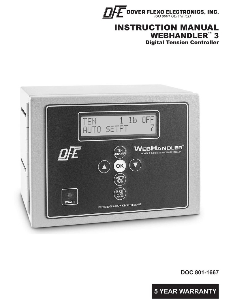
DFE STEADYWEB 6 User manual

Quick Start Guide
SteadyWeb™ 6
Tension Controller
DOC 801-2541 R1

This label indicates: “Read The Manual”
Make sure you read and understand all instructions and safety
precautions listed in this manual before installing or operating your
SteadyWeb™6 Tension Controller. If you have any questions
concerning the operation of your device or the information in this
manual, please contact us.
Email: [email protected]
Telephone: (603) 332-6150
•Observe all warning labels.
•Never remove warning labels.
Please review the SteadyWeb™ 6 Instruction Manual (DFE
P/N 801-0004) online at www.dfe.com to familiarize yourself
with all of the unit’s installation instructions, specifications,
safety information, and wiring diagrams.
WARNING: If this equipment is not connected or operated
in the manner specified, the operating safety of this unit or
of connected equipment cannot be guaranteed.
WARNING: The isolated output is designed to prevent
ground loops and noise. It is not intended or approved for
safety isolation of hazardous voltages. Do not install unit
where isolated circuit and chassis ground are more than 40
Vpk differential.

1
GENERAL DESCRIPTION
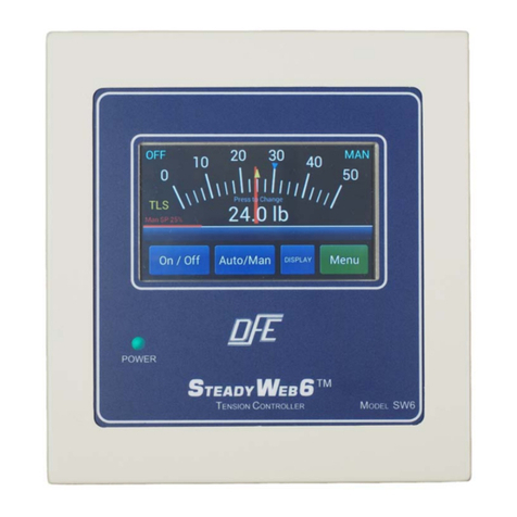
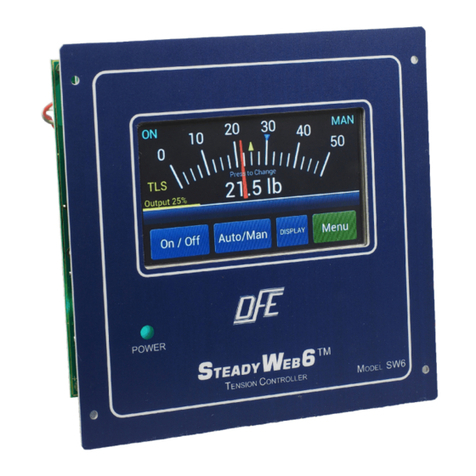
The SteadyWeb™6 is a digital tension controller designed to
automatically maintain tension of any continuous material at a
value selected by the equipment operator. The controller
combines ease of use with powerful control features and capability
that allow for effortless configuration and utilization over a wide
variety of tension control applications.
The SteadyWeb™6 can be powered by 24 VDC or with a built-in
100-240 VAC power supply and is available in panel mount and
enclosure mount configurations. The controller is offered in
multiple output versions. The user interface features a context-
sensitive 5" touch screen display. Illustrated prompts and color
graphics make set up easy and allow for a short operator learning
curve.
Basic functions of the controller are divided into three
components: amplifier, tension regulator and output converter.
MOUNTING
Select a mounting location on the machine frame or a wall that will
provide convenient operator interaction and easy screen viewing.
To ensure safety and proper operation, the SteadyWeb™ 6 must
be located away from dusty or wet environments. The unit should
be mounted to a secure wall or surface that can support in excess
of 30 lbs (13.6 kg). As the controller's front panel is hinged to the
bottom of the enclosure, ensure that the mounting location will
allow the front panel to swing open and down unobstructed. In
addition, ensure there will be adequate room below the controller
to allow for wire routing.
INSTALLATION INSTRUCTIONS
Panel Versions
For panel mount units, drill four holes and cut an opening centered
in the holes. Mount your Panel style controller in the hole using
four M3 (#4) nuts and screws.
Enclosure Versions
For enclosure mount units, drill and tap two M4 (#8) holes up from
the desired bottom of the enclosure to match the screw hole
dimensions on the back surface of the SteadyWeb™ 6. The

2
enclosure is fastened to the mounting surface you have chosen by
two M4 (#8) screws. Install the screws on the mounting surface.
Leave the screws loose about 6 turns. Position the keyholes in the
back panel of the enclosure over the screws and slide it down until
it locks in place. The cover must be open to tighten the mounting
screws and secure the enclosure in place.
Version P Only
The pneumatic enclosure should be located in the area of your
clutch or brake. Drill and tap four M3 (#4) holes in a rectangle. The
enclosure is fastened to the mounting surface you have chosen by
four M3 (#4) screws. The pneumatic servo is sensitive to any
mounting off it’s vertical axis. Mounting off vertical axis can cause
error in output pressure.
Version V Only
The High Voltage Output module, required for 45 VDC and 90
VDC only, should be located in the area of your clutch or brake. If
you are using the DIN Rail Clip (DRC) option, the V-Out module
may simply be clipped to a DIN rail. If you are using the Enclosure
mount style without the DRC option, drill and tap two M4 (#8)
holes to match the screw hole dimensions on the back surface of
the V-Out enclosure. The enclosure is fastened to the mounting
surface you have chosen by two M4 (#8) screws. Install the
screws on the mounting surface. Leave the screws loose about 6
turns. Position the keyholes in the back panel of the enclosure
over the screws and slide it down until it locks in place. The cover
must be open to tighten the mounting screws and secure the
enclosure in place. This module is not sensitive to mounting at any
angle.

3
USER INTERFACE
For ease of use, the critical-use buttons / critical-awareness
indicators are located consistently from one screen to the next.
Those buttons and indicators include blue On/Off, Auto/Man, and
Display toggle buttons on the bottom of the screen, and Tension
On/Off and Auto/Man status indicators in the upper LH and upper
RH corners of the display. The remaining button in the lower RH
corner is green and displays as Menu, Back or Save, depending
on what screen is current, and is used to advance to other menus,
to back out of menus, or to save selections or adjustments. For
more detail about buttons and indicators, see SECTION 1 -USER
INTERFACE OVERVIEW of the SteadyWeb™ 6 Instruction
Manual (DFE P/N 801-0004), hereafter referenced as The
Manual.
After first connecting the controller to power, the POWER LED will
light, and an error message will display, indicating that transducer
calibration must be completed (for other error messages, see
SECTION 11 - TROUBLESHOOTING of the The Manual).
CALIBRATION
To calibrate the controller, press the Menu button to enter the
menu mode. You can always exit Menu mode and return to
Display mode by pressing the Display button. Reference
Appendix B - MENU HIERARCHY of the The Manual for a
diagram of the complete menu structure.

4
Before calibrating the unit, you should verify that the Tension
Units, Tension Range, Tension Source, Calibration Weight
Percentage and Transducer Type are set to values you desire.
Press Menu > Calibration Menu > Calibrate buttons to get to the
Select Units screen. Confirm that the preset units are correct, or
choose your preferred units and then press OK.
After confirming or selecting new tension units, the controller will
similarly guide you through selection of the tension range, the
source of the tension signal, calibration weight percentage and
transducer type to be used. The tension range should be set at,
or just above your expected upper web tension limit.

5
With no other loads on the transducer roll, ZERO the transducers,
hang a calibration weight of known value with an inelastic rope,
strap or cable, and CALIBRATE the transducer signal, exactly as
instructed in SECTION 6- CALIBRATION of The Manual. The
calibration weight should weigh at least 10% of your maximum
expected web tension.
When the transducer signal is calibrated, press the Display button
to return to the tension display.
If additional calibration is required for inputs of Line Speed, Roll
Speed or Roll Diameter, refer to SECTION 6- CALIBRATION of
the The Manual.
Program settings are based on the tension zone in which the
controller is being used. For setting up Unwind, Intermediate and
Rewind Zones, refer to SECTION 7 - SETUP of The Manual.

6
Some PID (Proportional, Integral and Derivative) tuning may be
necessary to control tension optimally. Refer to SECTION 6 -
TUNING ADJUSTMENTS of The Manual for a PID control
overview and tuning procedure. Use the PID Tune View display
located at Menu > Calibration Menu > Tune PID Values to adjust
the PID terms for optimal control. See SECTION 5 - USER
INTERFACE OVERVIEW of The Manual for information on how
to utilize the PID Tune View display.
OPERATING INSTRUCTIONS
After calibrating, configuring and tuning the controller, save the
setup at Operator Menu > Store / Delete Setup, by selecting Store
Setup, scrolling to the desired setup location and pressing the
Select button. Follow the on-screen instructions to name the
setup (it helps to be descriptive), press the OK button, and press
the Save button on the next screen.
To recall a setup, visit Operator Menu > Recall Setup, scroll to the
desired setup and press the Recall button, press Recall again on
the next screen, and press OK.
For more information about saving, recalling and deleting setups,
see SECTION 2 - OPERATING INSTRUCTIONS of The Manual.

7
There are two tension display options, the Analog Meter and
Trend-Line Graph, which can be toggled back and forth using the
Display button.
For more information about the display mode, see SECTION 1 –
USER INTERFACE OVERVIEW of The Manual.
When in tension display screens, you may bring up velocity-
sensitive “+” and “-“ adjustment buttons by touching the tension
display. These buttons, for adjusting the Auto Setpoint or Manual
Output will time out a few seconds after discontinued use.

8
TROUBLESHOOTING
Most problems are caused by incorrect installation or
misapplication of the equipment, so it is important to read through
the manual and follow the proper installation, calibration and
configuration procedure.
The most common source of improper operation of tension
equipment is incorrect installation of the tension transducers or
using transducers of the wrong load rating. Refer to your
transducer instruction manual and
check the sizing and installation procedures to verify the
installation.
Note: Avoiding preloading the transducers
is very important. If changes cannot be made to menu selections,
check to make sure that the Anti-Tamper Lockout Jumper is not in
the locked position. Refer to manual for more detail.

©2022 DOVER FLEXO ELECTRONICS, INC. 0830 DOC 801-2541 R1
ALL RIGHTS RESERVED PRINTED IN USA
307 PICKERING ROAD
ROCHESTER, NEW HAMPSHIRE 03867-4630
U.S.A
TEL: (603) 332-6150
FAX: (603) 332-3758
E-mail: inf[email protected]m Internet: www.dfe.com
CANADA
EUROPE
MEXICO
UNITED KINGDOM
TAIWAN
KOREA
CHINA
INDIA
AUSTRALIA
SOUTH AFRICA
Other manuals for STEADYWEB 6
1
Table of contents
Other DFE Controllers manuals
Popular Controllers manuals by other brands

MSA
MSA 10033170 manual
Emerson
Emerson Asco Sentronic LP 617 Series installation manual
Burkert
Burkert 1094 Series operating instructions

Carel
Carel supernode operating manual

Boehringer
Boehringer 7700 Series Technical Manual and Operating and Maintenance Instructions

Pentair
Pentair MYERS K4563 Installation and service manual

