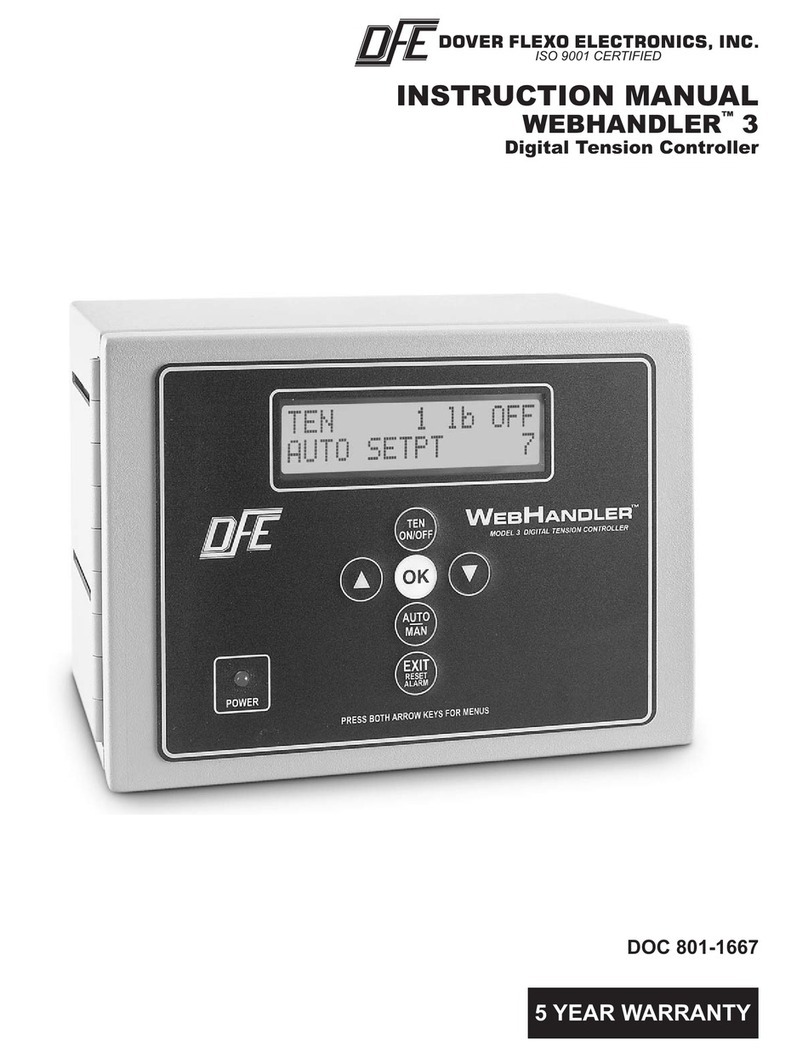
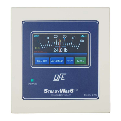
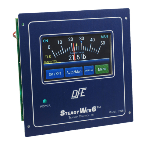
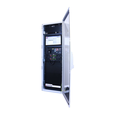
DFE STEADYWEB 6 Product manual

TECHNICAL REFERENCE MANUAL
Digital Tension Controller
STEADYWEB™6
DOC 801-2540

307 Pickering Road
Rochester, NH 03867-4630 U.S.A.
For assistance, please call:
TECHNICAL SERVICE - Installations, Start-Up, Troubleshooting, Repairs, Field
Service, Returns. [email protected]
CUSTOMER SERVICE - Replacement Parts, Individual Products, Questions about
Orders, Manuals. [email protected]
SALES - Product Information, Systems Application Questions, and
placing orders for standard products and special systems.
Telephone: (603) 332-6150 Fax: (603) 332-3758
E-mail: [email protected] Internet: www.dfe.com
©2019 Dover Flexo Electronics, Inc. All rights reserved. Dover Flexo Electronics has made reasonable effort to ensure accuracy of this
document. However NO WARRANTY, whether expressed or implied, is given regarding the completeness or correctness of information in
this document. Dover Flexo Electronics shall not be liable for damages of any kind arising from the use or misuse of this document. Dover
Flexo Electronics reserves the right to make changes, additions, and deletions to this document without notice and without obligation.

READ THIS!
*** SAFETY INFORMATION ***
Please read this manual prior to installing and operating the controller. Take care to follow
local codes and only allow properly trained individuals to operate or service the equipment.
Failure to follow the manual's instructions and practice safe working habits could result in
property damage, personal injury and/or death.
n WARNING:
Before servicing the SteadyWeb 6, power should be removed from the device. Failure to do
so could result in property damage, personal injury and/or death.
n CAUTION:
The SteadyWeb 6 contains circuit boards with static sensitive devices. When working
directly with these circuit boards, users should always practice proper grounding techniques,
including the use of ground straps.
*** INSTALLATION AND SETUP INFORMATION ***
Your SteadyWeb 6™ Controller has been properly configured at our factory. To install it and
start it up, it should only be necessary to use these sections of this manual:
Section 2 - Installation
Section 4 - Calibration
Section 6 - Tuning Adjustments
The other sections are for reference and for instruction if you wish to change the
configuration at some later time.
-a-

-b-

TABLE OF CONTENTS
SECTION ONE PRODUCT DESCRIPTION PAGE
1.1 General Description ............................................ 1
1.2 Tension Zones ................................................ 2
1.3 Versions of the Controller ....................................... 3
1.4 Specifications................................................. 3
1.5 Environmental Conditions ....................................... 5
1.6 Standard Features ............................................. 5
1.7 Options ..................................................... 7
1.8 Accessories..................................................7
SECTION TWO INSTALLATION
2.1 Dimensions .................................................. 8
2.2 Selection of Mounting Location ................................... 9
2.3 Safety & EMC Requirements..................................... 10
2.4 Installation Instructions ......................................... 12
2.5 Transducer Voltage Selection .................................... 12
2.6 Control Output Selection........................................ 13
2.7 Tension Output Selection ....................................... 14
2.8 Emergency Stop Configuration................................... 14
2.9 Customer +10/15V Output Selection............................... 15
2.10 Power Electrical Connections .................................... 16
2.11 Standard Electrical Connections .................................. 17
2.12 Option Card Mounting Locations .................................. 20
2.13 Pulse Tachometer Option Card Electrical Connections................. 20
2.14 DC Tachometer Option Card Electrical Connections .................. 21
2.15 Relay Option Card Electrical Connections........................... 21
2.16 External Output Module Cable Connections ....................... 22
2.17 High Voltage Output Module Electrical Connections ................... 23
2.18 Communication Options Cards Electrical Connections ................. 23
SECTION THREE USER INTERFACE OVERVIEW
3.1 Main Interface Description....................................... 24
3.2 Display Modes Descriptions ..................................... 24
3.3 Menu Display Mode and Navigation ............................... 25
3.4 PID Tune View................................................ 26
SECTION FOUR CALIBRATION
4.1 Tension Calibration............................................ 27
4.2 Line/Roll Speed Input Calibration ................................. 29
4.3 DC Tachometer Calibration...................................... 30
4.4 Pulse Tachometer Calibration.................................... 31
4.5 Diameter Input Calibration....................................... 33
4.6 Signal Filtering ................................................ 34
SECTION FIVE SETUP
5.1 Control Feedback Modes........................................ 35
5.2 Unwind Zone Setup ............................................ 35
5.3 Intermediate Zone Setup ........................................ 36
5.4 Rewind Zone Setup ............................................ 37
5.5 Soft Start Setup............................................... 38
5.6 Sample and Hold/Ratio Setup .................................... 39
5.7 Tension Limit Switch Setup...................................... 40
5.8 Diameter Alarm Setup.......................................... 40
5.9 Inputs Setup.................................................. 41
5.10 Relay Option Setup............................................ 42
5.11 Communication Options Setup ................................... 42
5.12 Tension On Relay Option ....................................... 43
5.13 Power On Settings............................................. 43
5.14 Anti-Tamper/Security Lockout ................................ 43
SECTION SIX TUNING ADJUSTMENTS
6.1 PID Control Tuning ............................................ 44
6.2 Tuning Procedure ............................................. 44
6.3 Tuning Examples.............................................. 45
6.4 Advanced Tuning Adjustments ................................... 46
6.5 Diameter Compensation ........................................ 46
6.6 Acceleration Compensation...................................... 47
SECTION SEVEN OPERATING INSTRUCTIONS
7.1 Basic Operation............................................... 48
7.2 Display Adjustments ........................................... 48
7.3 Saving and Recalling Setups..................................... 48
7.4 Transferring Setups to PC via USB................................ 48
7.5 Setting Auto/Manual Setpoints ................................... 48
7.6 Using Taper .................................................. 48
7.7 Resetting TLS Alarms.......................................... 48
7.8 Resetting Diameter Alarm....................................... 48
7.9 Zeroing Tension............................................... 48
SECTION EIGHT CARE AND MAINTENANCE ................................... 49

SECTION NINE TROUBLESHOOTING
9.1 General Troubleshooting Tips .................................... 50
9.2 Error Messages ............................................... 50
9.3 Diagnostic Screens ............................................ 52
SECTION TEN REPLACEMENT PARTS ...................................... 55
APPENDICES
APPENDIX: A Location of Jumpers and Adjustments (Figure 49) .................... 56
B Menu Hierarchy (Figure 50)...................................... 57
C Electrical Connections (Figures 51-52) ............................. 58
D Transducer Electrical Connections (Figure 53-54) ................... 60
E Typical Tensions of Various Materials.............................. 62
F Environmental Terms .......................................... 63
Terms and Conditions of Sale and Shipment ........................ 64
Index ....................................................... 65
LIST OF ILLUSTRATIONS
FIGURE 1. Front View of SteadyWeb6 ...................................... 1
2. Examples of Tension Zones ..................................... 2
3. Enclosure Version Dimensions and Views .......................... 8
4. Panel Version Dimensions and Views .............................. 8
5. Pneumatic Enclosure Dimensions for Version P ...................... 9
6. High Voltage Output Enclosure Dimensions for Version V .............. 9
7. Enclosure Version Service Access ................................ 11
8. Output Jumpers............................................... 14
9. Setup Jumpers................................................ 15
10. 24VDC Power Electrical Connections .............................. 16
11. AC Power Electrical Connections ................................. 17
12. Standard and 0-10VDC Control Board Electrical Connections . . . ........ 18
13. Control Board Transducer Electrical Connections and Remote Option..... 19
14. Option Card Mounting Locations .................................. 20
15. Pulse Tachometer Electrical Connections ........................... 20
16. DC Tachometer Electrical Connections............................. 21
17. Relay Electrical Connections ..................................... 21
18. 24VDC Connections for Brakes and Clutches........................ 22
19. External Output Module Cable Connections ......................... 23
20. High Voltage Output Module Electrical Connections ................... 23
21. SteadyWeb6 User Interface...................................... 24
22. Main Menu Screen............................................. 25
23. PID Tune View Screen ...................................... 27
24. Selection of Tension Units.................................... 27
25. Selection of Tension Range .................................. 27
26. Selection of Tension Source.................................. 27
27. Selection of Calibration Weight................................ 27
28. Selection of Transducer Type................................. 28
29. Review of Calibration Settings................................. 28
30. Zero Transducer Screen..................................... 28
31. Zero Operation Complete ....................................... 28
32. Web Path For Calibration ....................................... 28
33. Cal Not Ready ............................................... 29
34. Cal Ready ................................................... 29
35. Cal Successful................................................ 29
36. DC Tachometer............................................... 30
37. Pulse Tachometer............................................. 32
38. Anti Tamper Lockup Jumper..................................... 43
39. Tuning Screen Showing Overshoot ................................ 45
40. Tuning Screens Showing Adjustment Responses..................... 45
41. Derivative Noise............................................... 45
42. Screens Showing Wobble ....................................... 46
43. Diameter Compensation PID Transition ............................ 47
44. Control Board Showing Jumper Locations .......................... 56
45. Menu Hierarchy ............................................... 57
46. Standard and 0-10Vdc Control Board Electrical Connections . . . ......... 58
47. Control Board Transducer Electrical Connections and Remote Option..... 59
48. Models C, RS, F, TR, and NW Transducer Wiring .................... 60
49. RFA, LT, and VNW Transducer Wiring ............................. 61

1 PRODUCT DESCRIPTION
1.1 GENERAL DESCRIPTION
The SteadyWeb™6 is a digital tension controller designed to automatically maintain tension of any continuous
material at a value selected by the equipment operator. The controller combines ease of use with powerful
control features and capability that allow for effortless configuration and utilization over a wide variety of tension
control applications.
The SteadyWeb™6 can be powered by 24VDC or with a built-in 100-240VAC power supply and is available in
panel mount and enclosure mount configurations. The controller is offered in multiple output versions. The user
interface features a context-sensitive 5" touch screen display. Illustrated prompts and color graphics make set up
easy and allow for a short operator learning curve.
Basic functions of the controller are divided into three components: amplifier, tension regulator and output
converter.
Figure 1 - FRONT VIEW OF SteadyWeb™6
1. Amplifier
The first component is a tension amplifier, which supports all Dover Flexo Electronics tension transducers (the
transducers measure the actual web tension). It includes a regulated power supply to excite the transducers
and circuitry to amplify and measure the transducer output signal. Intelligent excitation circuitry provides
automatic excitation voltage selection and monitors for transducer wiring errors or fault conditions, such as a
short circuit or open circuit conditions.
1

1.1 GENERAL DESCRIPTION continued....
2. Tension Regulator
The second component is the tension regulator. The controller compares the measured tension to the Auto
setpoint value and adjusts an output signal to equalize the measured and desired tension. The regulator
function is performed by software and may be influenced by other signal inputs, such as web speed and roll
diameter, as dictated by operator-adjustable settings. Regulation is achieved with a PID (Proportional,
Integral, Derivative) based control loop with advanced capabilities such as roll diameter compensation and
web acceleration compensation.
3. Output Converter
The third component is the output stage, the signal from which is used to actuate a brake, clutch, or variable
speed DC or AC drive which in turn creates the actual web tension. The output stage is available in several
application-dependent versions. Standard in every controller is an isolated control output (adjustable range
within the limits of ± 10 Volts or 4-20 mA). Optionally, a 0-24VDC output stage may be included internal to the
controller to drive 24V devices drawing up to 2.5A. Higher current 0-24V devices may draw customer-
supplied power through the controller's terminals. Optional external output modules are available to drive
higher voltage electrical devices with 0 – 45/90 VDC @ 5 Amps and pneumatic devices with 2 – 75 psi.
n WARNING:
The isolated output is designed to prevent ground loops and noise. It is not intended or approved for safety
isolation of hazardous voltages. Do not install unit where the isolated circuit and chassis ground are more than
40Vpk differential.
n WARNING:
AC versions of the SteadyWeb™6 controller are designed for single phase AC operation only. To prevent product
damage and potential hazard, do not connect them across three phase lines or three phase circuits.
1.2 TENSION ZONES
Tension zones are created by driven or braked nip rolls, drag bars, braked unwind, driven unwind, or rewind
shafts, or anything else that can increase or decrease web tension. One of these elements is at each end of
every tension zone.
Many machines that process a continuous web have more than one tension zone. The SteadyWeb™6 controller
can be used in all tension zones, when properly configured for the zone it will be used in. See Figure 2 for
examples of tension zones.
Figure 2 - EXAMPLES OF TENSION ZONES
2

1.3 VERSIONS OF THE CONTROLLER
The SteadyWeb™6 controller is available in multiple output, mounting and power configurations as described
below.
A. OUTPUT The SteadyWeb™6 is available with one of three outputs:
1. Standard Isolated Output (D). The standard D version is used to control DC drives or other variable
speed drive systems. It offers a jumper-selectable voltage or current output. The voltage output is from 0
to +/-10VDC, or a user-adjustable range within that window, such as 0 to 10VDC, 0 to +/-5VDC, etc. The
current output uses an industry standard 4 to 20mA signal. The control output is isolated from chassis and
transducer ground.
n WARNING:
The isolated output is designed to prevent ground loops and noise. It is not intended or approved for
safety isolation of hazardous voltages. Do not install unit where the isolated circuit and chassis ground are
more than 40Vpk differential.
2. Pneumatic Output (P). The P version is used to actuate any air operated brake or clutch. It includes a
servo valve, air filter and pressure regulator installed in a separate enclosure which is fed a 4-20mA signal
from the D version of the controller (as described above). The pneumatic output range is 1 to 75 psi (0.07
bar to 5.17 bar).
3. High Voltage Output (V). Embedded within the SW6 Controller is a standard 24V output stage to drive
24V brakes and clutches up to 2.5A drawn current. Devices drawing more than 2.5A at 24V can be
accommodated with guidance from DFE Engineering. To operate brakes or clutches at more than 24V,
including eddy current clutches, the 45 and 90 Vout options are available in an outboard module which is
fed a 0-10V signal from the D version of the controller (described above) and employs a Silicon Controlled
Rectifier (SCR) to deliver variable voltage of up to 90VDC. The 24VDC output is not available with the
230VAC input.
B. MOUNTING The controller is available in two mounting configurations.
1. Open Mount (O). The open (panel) mount version can be mounted directly into a cabinet or enclosure
cutout.
2. Enclosure Mount (E). The enclosed version can be mounted against any surface strong enough to
reliably support the controller.
C. POWER The controller is available in two power versions.
1. 24VDC (24). The DC version is powered from a 24VDC +/-10% supply.
2. AC (AC). The AC version includes a universal AC power supply, which can be powered from a 100-
240VAC, 50-60Hz supply.
n WARNING:
AC versions of the SteadyWeb™6 controller are designed for single phase AC operation only. To prevent
product damage and potential hazard, do not connect them across three phase lines or three phase
circuits.
1.4 SPECIFICATIONS
Power Input:
DC:
• 24VDC +/-10% , 0.6 Amps Typical, 2.2 Amps Internal
Fusing (resetting thermal fuse)
Optional AC Supply:
• 100-240VAC +/-10%, 50-60Hz single phase
• 2.2 Amps @ 115VAC Typical
• 1.2 Amps @ 230VAC Typical
• Inrush Current 40A @ 230VAC (cold start)
Control Output:
Version D
• 0 to +/-10VDC OR 4-20mA (jumper-selectable), both
isolated from input power and transducer circuitry
• 0 to +/-10VDC max loading is 5mA. This requires a
2000 Ohm or greater input resistance for equipment
connected to this output
• 4-20mA max loop resistance is 500 Ohms.
Transducer Signal Input:
• 500mV at rated load per pair of STD transducers
• 1,000mV at rated load per pair of XR transducers
Customer 10/15VDC Supply:
• 10/15VDC (jumper-selectable), 100mA max load.
3

1.4 SPECIFICATIONS continued . . .
Transducer Excitation:
• 5VDC for STD transducers, 10VDC for XR
transducers (automatically software set per sensed
transducer resistance, or manually fixed through user
configuration settings)
• 35mA per half bridge (70mA total) software short
circuit protection
• Duration of excitation short-circuit: Infinite
Tension Output:
All Versions:
• 0 to +10VDC OR 0 to 1mA (jumper-selectable)
• 0 to +10VDC max loading is 5mA. This requires a
2000 Ohm or greater input resistance for equipment
connected to this output
• 0 to +10VDC and 0 to 1mA signal capable of under-
range and over-range, -14% to 120% of full scale (-
1.4VDC to 12VDC / -0.14mA to 1.2mA), to indicate
over-range or error conditions
• 0 to 1mA meter output designed for 50 Ohm
impedance meter.
Digital Inputs:
• Soft Start, Hold, Ratio, Remote Tension On, Remote
Tension Off, Remote Auto, Remote Manual
• Activated by contact with power ground (falling edge)
• Internal weak pull-up resistors to 3.3VDC
• Max 24VDC input protection
Digital Outputs:
• 3.3V digital diameter alarm output
Analog Signal Inputs:
• Line Speed, Roll Speed, Diameter, Remote Auto
Setpoint, Remote Manual Setpoint, RTA1, RTA2
• Designed for 0-10VDC input signal, 0-12VDC range
sense capability
• Max 24VDC input protection
Tension Precision:
• Max error of 1% over temperature range. 0.1%
Typical
Zero (Tare) Range:
•Minimum 95% of transducer rating
Calibration Range:
• 50:1 max
Control Loop Time:
• Less than 5mSec
Transducer Tension Analog to Digital Converter
(ADC) Resolution:
• 16-Bit at 242Hz sample rate
• 20.62μV Resolution with 5V Excitation (STD
Transducers)
• 41.24μV Resolution with 10V Excitation (XR
Transducers)
Analog Signals* Analog to Digital Converter (ADC)
Resolution:
• * (Line Speed, Roll Speed, Diameter, Remote Auto
Setpoint, Remote Manual Setpoint, RTA1, RTA2)
• 12-Bit at 242Hz sample rate
• 2.93mV Resolution
Control Output Digital to Analog Converter (DAC)
Resolution (D Version):
• 12-Bit at 242Hz update rate.
• -10VDC to 10VDC Out: 6.0mV Resolution
• 4-20mA Out: 9.6μA Resolution
Tension Output Digital to Analog Converter (DAC)
Resolution:
• 12-Bit at 242Hz update rate.
• 0-10VDC Out: 3.3mV Resolution
• 0-1mA Out: 0.33uA Resolution
Pneumatic Enclosure (Version P only):
• Air Input: 125 psi Max.
• Air Output: 2 to 75 psi (0.07 to 5.17 bar)
• Servo Valve Drive: Signal: 4 to 20mA
• Air Connection In: 3/8" NPT
• Air Connection Out: 1/4" NPT
Weight:
• DC Panel Mount: 1.6 lbs. (0.73 kg)
• AC Panel Mount: 3.1 lbs. (1.41 kg)
• DC Enclosure Mount: 5.1 lbs. (2.32 kg)
• AC Enclosure Mount: 6.6 lbs. (3.00 kg)
• Pneumatic Module: 4.6 lbs. (2.09 kg)
• High Voltage Output Module: 2.9 lbs. (1.32 kg)
4

1.4 SPECIFICATIONS continued . . .
High Voltage Output Module (Version V only):
Power Input:
• 115 OR 230VAC 50/60Hz single phase
Note: 115 / 230 VAC factory set. Specify when
ordered
• Input Power fused at 5,125A @ 115 VAC
Input Power fused at 5.063A @ 230VAC
• Low Voltage Circuitry fused at 125mA @ 115VAC
Low Voltage Circuitry fused at 63mA @ 230VAC
Output:
• 0 to 24, 45, or 90VDC, all @ 5 Amp with 115VAC In
OR
• 0 to 45 or 90VDC, all @ 5 Amp with 230 VAC In
Signal Input:
• 0-10VDC
Optional RS232 Card:
• Selectable Baud Rate: 4800, 9600, 14400, 19200
• Modbus RTU Interface, Jumper Configurable Null
Modem or Standard communication
Optional RS485 Card:
• Selectable Baud Rate: 4800, 9600, 14400, 19200
• Modbus RTU Interface
• Jumper Configurable 2 or 4 wire mode
Optional Pulse Tachometer Card:
• Input: 0-50kHz, 1-50VDC pulses
Optional DC Tachometer Card:
• 5-15VDC Input: 0-15VDC
• 15-250VDC Input: 0-250VDC
Optional Relay Card:
• Max Voltage: 230VAC
• Max Current: 5A (with resistive load)
Optional Enclosure:
• Steel, powder resin painted, NEMA 1
• Dual Transducer Connectors - Amphenol MS3106A-
10SL-3S
1.5 ENVIRONMENTAL CONDITIONS (Ref. Appendix F for further information)
This section applies to equipment designed to be safe at least under the following conditions:
• Indoor use.
• Altitude up to 6500 ft (2000 meters).
• Temperature range: 32° F to 104° F (0° C to 40° C).
• Maximum relative humidity 95% over the temperature range (non-condensing).
• Main supply voltage fluctuations not to exceed +/-10% of the nominal voltage.
• Main supply transient overvoltages according to overvoltage category II of IEC 60364-4-443.
• Pollution Degree 2 in accordance with EN61010-1:2001.
1.6 STANDARD FEATURES
•Flexible, Powerful Configuration. The controller can be utilized in unwind, rewind, or intermediate tension
zones. It can be configured for standard (transducer feedback only) tension control, for line speed follow with
tension trim or for diameter compensated line speed follow with tension trim modes of control. The PID based
control algorithm features adaptive diameter compensation and acceleration compensation capability to
handle a wide array of tension control applications.
•Informative, Intuitive User Interface. The SteadyWeb™ 6 user interface features a full color 5” touchscreen
display for presenting real time tension and related process information and facilitating controller configuration
and calibration. Illustrated prompts and color graphics make set up a breeze and allow for a short operator
learning curve. Real time information is displayed in a clear and highly configurable manner with operator
selectable use of line graphs, or an analog meter. The menu system is easily navigable and on-screen
information pages are provided for every menu, setting and function, acting as an on-screen manual
•Multiple Stored Setups. Up to 30 Setups can be stored in addition to the ACTIVE Setup. Operator
programmable descriptive Setup names are possible with the controller's alphanumeric naming capability.
Setups can be uploaded and downloaded to a PC via a USB port.
•Anti-Tamper Switch (Operator Lockout) Disables operator access to certain menu functions and settings.
5

1.6 STANDARD FEATURES continued...
•Automatic Excitation Voltage Selection. An intelligent transducer excitation system allows the controller to
automatically adjust the excitation voltage in accordance with the connected transducer type; 5VDC for
Standard (STD) transducers or 10VDC for Extended Range (XR) transducers. The system is also capable of
detecting transducer wiring errors or fault conditions, such as a short circuit or open circuit conditions.
Automatic excitation power shut down during short circuit or over-current conditions help protect both the
controller and the connected transducers from damage.
•Digital Calibration and Control Technology. Digital transducer calibration and tension control settings mean
the controller will not suffer from the time, temperature or vibration induced drift that can be associated with
analog circuitry and components.
•Isolated Control Output. Standard +/-10VDC (or a user-adjustable range within +/-10VDC) or 4-20mA
(jumper-selectable) control output isolated from chassis and transducer ground. Designed to prevent ground
loop and noise issues common in industrial environments.
n WARNING: The isolated output is designed to prevent ground loops and noise. It is not intended or
approved for safety isolation of hazardous voltages. Do not install unit where the isolated circuit and chassis
ground are more than 40Vpk differential.
•Remote Tension Readout. 0 to 10VDC or 0 to 1mA (jumper-selectable) external meter or monitoring output
proportional to tension. The 0 to 1mA output is designed to drive a 50 Ohm meter.
•Display Tension Damping. Adjustable tension damping reduces flicker on the display and makes the tension
readout more readable in certain situations.
•Tension Limit Switch (TLS). An alarm is triggered to alert operators to preset low or high tension conditions.
A TLS alarm message is displayed on the LCD and an optional relay can be energized. The alarm can also
be configured to disable the control output. Purchase TLS option to get relay for external alarm use.
•Soft Start. Used on braked unwinds. Actuated either automatically upon a loss of tension below a preset trip
point (after an adjustable delay), by machine speed dropping below a preset speed trip point (after an
adjustable delay), or immediately upon an external contact closure. In Soft Start mode, controller output is
reduced to a preset (user-adjustable) low level to prevent brake lockup when the machine starts. When
tension or line speed rises above their respective trip points or the Soft Start contact opens, the controller
output switches to automatic control mode through a bumpless transfer.
•Taper. Used in rewind zones. Taper causes tension to decrease as the roll diameter increases. The roll
diameter is calculated from line and roll tachometer signals or measured directly by a follower roll or ultrasonic
sensor. Taper helps produce a better quality roll by eliminating telescoping, crushed cores and too tight or too
loose rolls.
•Hold / Ratio. Used to sample and hold and/or ratio the output or setpoint. Ratio can also be used to ratio to
the real time line speed to allow for a smooth transfer between rolls in rewind splicing applications.
•Remote User Control Inputs. Terminal block inputs are provided to allow for remote Tension On / Tension
Off and Auto mode / Manual mode toggling using external switches or relays. Analog terminal inputs are also
provided for remote Auto setpoint and Manual setpoint signals, either from a potentiometer or from an external
0-10VDC source, such as from a Programmable Logic Controller (PLC).
•Remote Tension Amplifier Inputs (RTA) . Two sets of RTA inputs allow bypassing the internal tension
amplifier to provide a tension signal by an external remote amplifier or indicator. This allows use of special
amplifier functions, such as intrinsic safety, which are not available in the SteadyWeb™6 controller, or to
connect multiple pairs of transducers to the controller.
•Analog Line, Roll and Diameter Inputs. 0-10VDC input terminals are provided for Line Speed, Roll Speed,
and Roll Diameter input signals. The speed inputs can be fed from tachometer outputs and the diameter input
can be fed from a rider assembly or ultrasonic range finder. These signals can be used for Line Speed Follow
and Diameter Compensated Line Speed Follow modes of operation. These signals can also be used for
advanced tuning functions, such as Acceleration Compensation and Diameter Compensation. Optional
tachometer cards can be used to handle voltages outside the 0-10VDC range or to interface with pulse
tachometers.
•+10/15VDC Customer Supply. A jumper-selectable 10VDC or 15VDC, 100mA supply is provided to feed
external potentiometers or to power diameter measurement sensors.
•Manual Control Mode The controller output is determined only by the setting of the Manual setpoint value.
No output change occurs unless the setting is changed. Used during machine set up or troubleshooting.
•Automatic Control Mode The controller output is determined by the difference between the web tension and
the Auto setpoint value. The internal regulator automatically varies the output as required to maintain the set
tension.
6

1.6 STANDARD FEATURES continued...
•Emergency Stop The controller immediately goes into full output or minimum output (jumper-selectable) upon
a break in the Emergency Stop circuit. Full output is traditionally used in braked unwind applications, to stop
the roll of material quickly. Minimum output is used for other applications. The Emergency Stop circuit can be
bypassed if no Emergency Stop function is desired.
1.7 OPTIONS
•230 Volt Power (230). 230 volt 50/60 Hz power input. V version only. (For V-out module, controller can be
24Vdc).
•24V or 45V Output (24,45). 24V or 45V output. Version V only.
• 4-20mA Output (420). 4-20mA current output. This replaces the standard 0-10V control output.
• Bipolar 10 Volt Output (B10). -10V to +10V output. Used on bi-directional machines (ex: inspection
machine), or in Line Speed Follow. D version only.
•Diameter Alarm (DA). Unit produces an output at a pre-determined roll diameter. Requires diameter signal.
•Speed Follow. This is a function normally used on Version D controlling tension in an intermediate zone or
surface driven rewinds and unwinds. The Control board contains a regulator circuit, separate from the tension
regulator, that can accept a 0 to 10V line speed signal, one from a DC tach (SFD), or a pulse tach (SFP). The
line speed signal causes the output of the controller to follow (go up and down with) line speed. The output of
the tension regulator then trims the follower output as needed to maintain set tension.
• DIN-Rail Mounting Clip (DRC). Fits 35mm DIN rail. Available only on V version, for V-Out Module.
• Metric Pneumatic Fittings (MPF). “P” Version only.
•Reverse Output (RO). Increases output when tension exceeds set point, and decreases when tension drops
below set point. Used in intermediate applications where transducers are located after the nip rolls being
controlled by the transducers or for driven unwinds.
•RS232 (RS23) or RS485 (RS48). An optional communications card provides serial communication using the
MODBUS RTU protocol, allowing easy integration with computers or PLCs.
•Serial Data Connector (DB9). 9-pin connector for data transfer when using the RS232 and RS485 options.
Enclosure version only.
•Remote Tension Amplifier (RTA). The internal tension amplifier is bypassed and the tension signal is
provided by an external remote device such as the FireGuard™. This allows use of special indicator functions,
such as intrinsic safety, which are not available in the SteadyWeb™6 controller or additional transducers.
•Tension Limit Switch (TLS). An open collector output actuates at a pre-set adjustable trip point. Can be used
as a web break detector, or high tension warning. Low and high trip points are independently adjustable.
Trigger delay is adjust-able. Includes relay for triggering external alarm or light. Not compatible with TOR
option - only 1 relay per controller.
•Tension On Relay (TOR). Tension On Relay provides a 250V, 5A relay interface. The relay function is
operator-adjustable, and can be used for various functions such as a Tension On or Tension Limit Switch
indicator. Not compatible with TLS relay function - only 1 relay per controller.
•Taper Tension. For rewind applications only. Causes tension to decrease as roll diameter increases as
calculated electronically using inputs from: two DC tachs (TTD), two pulse tachs. (TTP), one DC tach and one
pulse tach (TTDP), or as sensed by a follower roll or ultrasonic sensor (TTF). Helps produce a better quality
roll by eliminating telescoping, crushed cores, too tight or too loose rolls. Taper is adjustable from 0 to 100%.
1.8 ACCESSORIES
•Remote Tension Meter. Analog, 1 mA (DFE P/N: 722-1385) supplied as a single unit. Must be installed by
user. This meter is also available in its own enclosure (DFE P/N: 723-2682, meter included).
•Nonstandard Meter Scale. Any other meter scale than standard ones offered by DFE. See Specifications
for standard scales. Applies to remote tension meter listed above.
• Remote Digital Tension Meter. 4 digit, 0-1 mA (DFE P/N: 723-2307) supplied as a single unit without
enclosure, or with enclosure (DFE P/N: 723-2660, meter included). Must be installed and powered (+24V) by
user.
•Ultrasonic Roll Diameter Sensor. Compact user-adjustable sensor with a 0-10V output proportional to
target distance. P/N 149-0002.
DFE also offers a wide variety of interconnect cables. Please consult your Applications Engineer for more
information.
7

2 INSTALLATION
The Anti-Tamper / Security Lockout is a jumper, shipped in the unlocked position, and may be used to prevent
unauthorized changes to the controller. Refer to Section 5.14 for more detail regarding this feature.
2.1 DIMENSIONS inches (mm)
Figure 3 - ENCLOSURE VERSION DIMENSIONS and VIEWS
Figure 4 - PANEL VERSION DIMENSIONS and VIEWS
8

2.1 DIMENSIONS continued...
Figure 5 - PNEUMATICS ENCLOSURE DIMENSIONS FOR VERSION P
Figure 6 - HIGH VOLTAGE OUTPUT ENCLOSURE DIMENSIONS FOR VERSION V
2.2 SELECTION OF MOUNTING LOCATION
1. Enclosure Mount Versions
Select a mounting location on the machine frame or a wall that will provide convenient operator interaction and
easy screen viewing. To ensure safety and proper operation, the SteadyWeb™6 must be located away from
dusty or wet environments. The unit should be mounted to a secure wall or surface that can support in excess
of 30 lbs. (13.6 kg). As the controller's front panel is hinged to the bottom of the enclosure, ensure that the
mounting location will allow the front panel to swing open and down unobstructed. In addition, ensure there
will be adequate room below the controller to allow for wire routing.
9

2.2 SELECTION OF MOUNTING LOCATION continued..
2. Panel Mount Versions
The panel mount configuration should be installed in a cabinet or enclosure that can support in excess of 15
lbs. (6.8 kg). The controller should be positioned for convenient operator interaction and easy screen
viewing. To ensure safety and proper operation, the SteadyWeb™6 must be located away from dusty or wet
environments. Ensure there is a minimum of 5” (12.7 cm) clearance behind the mounting panel to allow for
physical fit of the controller with room for air circulation. In addition, ensure there will be adequate room below
the controller's mounting location to allow for wire routing to the input/output terminal blocks.
- IMPORTANT: Ensure flex cable does not abrade on cutout! See Fig. 4 on page 8.
3. Version P Only
The pneumatic enclosure is designed for mounting close to your brake or clutch. This allows for a short length
of tubing between the pneumatic output and the brake or clutch. In addition to a shop air supply connection, a
signal cable must be run between the pneumatic unit and the controller. Choose a location which is free from
vibration and that is located away from dusty or wet environments. The pneumatic enclosure should be
mounted to a secure wall or surface that can support in excess of 20 lbs. (9.1 kg). Ensure there will be
adequate room around the mounting location for wire and pneumatic tube routing. Air should be clean and dry
- no oil.
4. Version V Only
The High Voltage output enclosure for 90V and 45V output versions is designed for mounting close to your
electric brake or clutch. Unlike for the 90V and 45V output versions, the 24V version is fully enclosed within
the SteadyWeb 6 Enclosure Mount and Panel Mount versions, and requires no separate high voltage output
enclosure. It requires a dedicated AC power feed. In addition, a signal cable must be run between the Vout
module and the controller. To ensure safety and proper operation, the V-Out enclosure must be located away
from dusty or wet environments. It should be mounted to a secure wall or surface that can support in excess
of 12 lbs. (5.5 kg). Ensure there will be adequate room around the mounting location for wire routing.
2.3 SAFETY AND EMC REQUIREMENTS
n WARNING: If this equipment is not connected or operated in the manner specified, the operating safety of this
unit or of connected equipment cannot be guaranteed.
n WARNING: The isolated output is designed to prevent ground loops and noise. It is not intended or approved
for safety isolation of hazardous voltages. Do not install unit where isolated circuit and chassis ground are more
than 40Vpk differential.
n WARNING: AC versions of the SteadyWeb™6 controller are designed for single phase AC operation only. To
prevent product damage and potential hazard, do not connect them across three phase lines or three phase
circuits.
1. AC Power Configuration
For safety reasons, it is necessary to use appropriate wiring for your line voltage connections and for safety
grounding. Make your ground connection between a reliable earth ground and the safety ground of your
controller using a wire with a gauge of at least 16 AWG (or a cross-sectional area of at least 1mm^2) and
insulation rating of at least 600V.
Make your AC line voltage connections with wire gauge of at least 16 AWG (or a cross-sectional area of at
least 1mm^2) and insulation rating of at least 600V for each conductor.
2. DC Enclosure Mount Configuration
For DC enclosure mount units, the length of wire inside the enclosure should be long enough to allow the
front panel to open fully without putting any strain on wire, but no longer. Flexible, stranded wire should be
used to allow flexing around the enclosure hinge when opening and closing the front panel. Solid wire should
not be used. Be sure to route the 24VDC power supply wires through the side cable clamp as shown in
Figure 10, 24VDC Electrical Connections.
3. AC and DC Power Configurations
Secure the power wiring to prevent inadvertent removal or strain on the input terminal. For enclosure mount
units, this wiring should be secured at the power inlet of the enclosure. An external switch or circuit breaker is
required for power disconnection of the SteadyWeb™6. It is recommended that this switch or circuit breaker
be located near the equipment and be well labeled.
4. Version V Only
For safety reasons, it is necessary to use appropriate wiring for your line voltage connections and for safety
grounding. Make your ground connection between a reliable earth ground and the safety ground of your V-Out
10

2.3 SAFETY AND EMC REQUIREMENTS continued...
module using a wire with a gauge of at least 12 AWG (or a cross-sectional area of at least 2mm^2) and
insulation rating of at least 600V. Make your AC line voltage connections with wire gauge of at least 12 AWG
(or a cross-sectional area of at least 2mm^2) and insulation rating of at least 600V for each conductor. Secure
this wiring to prevent inadvertent removal or strain on the input terminal.
An external switch or circuit breaker is required for power disconnection of the V-Out module. It is
recommended that this switch or circuit breaker be near the equipment, and be well labeled.
It is necessary to remove the the V-Out Module cover (held in place by four M3 screws) to mount the non-
DIN rail version of the output module to a supportive wall. It is also necessary to remove the cover to access
and wire into the module's terminal blocks
n WARNING:
Always keep the V-Out Module enclosure closed with the cover firmly tightened down while power is
connected to the module.
5. Shielding
For maximum EMC performance, a proper transducer installation, including shielded cables must be used.
The following is a list of cables available from DFE which meet this requirement:
• For type C, RS, and F transducers (Use 2 cables, 1 cable per transducer): 721-0084 CN 3-conductor cable
for panel mount, 721-0085 CC 3-conductor cable for enclosure mount.
• For type RFA, LT, VNW, NW, and TR transducers: 721-0964 CN 6-conductor cable for panel mount, 721-
0995 6-conductor cable for enclosure mount.
Other cables manufactured by DFE also meet this requirement. Contact DFE for more information.
In addition to the transducer cable shielding, a shielded meter cable (DFE P/N: 721-0967, 15 ft., other lengths
available) and meter in enclosure (DFE P/N: 723-2682) are required when an accessory meter is used.
Cable shielding must be attached to a SHIELD connection on the terminal blocks, or to an appropriately
grounded enclosure.
6. Enclosure Mount Versions
Enclosure mount versions of the SteadyWeb™6 controller use a hinged enclosure. The front of the
controller hinges down to allow access to the internal circuit boards and adjustments. The enclosure should
always be mounted in a location that allows unobstructed opening and closing of the front panel. When the
front panel is closed, an M3 screw on the top of the enclosure must be tightened down to firmly keep the panel
in place and prevent unintentional opening (see Figure 7, Enclosure Version Service Access). The panel
should be kept shut with the latch screw tight at all times when the controller is in use. Only qualified service
technicians may open the enclosure and access the internal circuit boards.
Figure 7 – ENCLOSURE VERSION SERVICE ACCESS
11

2.3 SAFETY AND EMC REQUIREMENTS continued...
n WARNING:
Always keep the enclosure closed with the latch screw firmly tightened down during normal operation.
n WARNING:
Only qualified personal may open the controller enclosure to access internal circuit boards and adjustments.
When working with AC powered versions of the controller, the AC power rails will be exposed when the front
panel is opened. Standard safety precautions should always be used when working around AC power rails.
Unless the servicing requires power applied to the unit, power should always be removed before opening the
enclosure.
7. Electrostatic Discharge Protection
The controller circuitry contains sensitive devices that are susceptible to damage from ESD (Electrostatic
Discharge). The controller's power inputs, I/O terminals, push buttons, etc., have been designed to be
protected from the high level of ESD present in typical industrial and web processing environments. When
accessing the circuit boards directly, however, unprotected devices are exposed to direct contact. Because of
this, proper ESD precautions should be followed when servicing the controller, such as wearing ground straps.
2.4 INSTALLATION INSTRUCTIONS
1. Panel Versions
For panel mount units, drill four holes and cut an opening centered in the holes (see Section 2.1, Fig. 4-Panel
Mount Dimensions and Views). Mount your Panel style controller in the hole using four M3 (#4) nuts and
screws.
2. Enclosure Versions
For enclosure mount units, drill and tap two M4 (#8) holes up from the desired bottom of the enclosure to
match the screw hole dimensions on the back surface of the SteadyWeb™6 enclosure (see Section 2.1, Fig.
3-Enclosure Mount Dimensions and Views). The enclosure is fastened to the mounting surface you have
chosen by two M4 (#8) screws. Install the screws on the mounting surface. Leave the screws loose about 6
turns. Position the keyholes in the back panel of the enclosure over the screws and slide it down until it locks
in place. The cover must be open to tighten the mounting screws and secure the enclosure in place.
3. Version P Only
The pneumatic enclosure should be located in the area of your clutch or brake. Drill and tap four M3 (#4)
holes in a rectangle (see Section 2.1, Fig. 5-Pneumatic Enclosure Dimensions). The enclosure is fastened to
the mounting surface you have chosen by four M3 (#4) screws. The pneumatic servo is sensitive to any
mounting off it’s vertical axis. Mounting off vertical axis can cause error in output pressure.
4. Version V Only
The High Voltage Output module, required for 45VDC and 90VDC only, should be located in the area of your
clutch or brake. If you are using the DIN Rail Clip (DRC) option, the V-out module may simply be clipped to a
DIN rail. If you are using the Enclosure mount style without the DRC option, drill and tap two M4 (#8) holes
(see Section 2.1, Fig. 6-High Voltage Module Dimensions) to match the screw hole dimensions on the back
surface of the V-Out enclosure. The enclosure is fastened to the mounting surface you have chosen by two
M4 (#8) screws. Install the screws on the mounting surface. Leave the screws loose about 6 turns. Position
the keyholes in the back panel of the enclosure over the screws and slide it down until it locks in place. The
cover must be open to tighten the mounting screws and secure the enclosure in place. This module is not
sensitive to mounting at any angle.
2.5 TRANSDUCER VOLTAGE SELECTION
Unlike previous DFE products, the transducer excitation voltage in the SteadyWeb™6 is not normally set via a
jumper or switch setting. The SteadyWeb™6 features an intelligent transducer excitation system that allows it to
automatically adjust the excitation voltage in accordance with the type of connected transducers (5VDC for
Standard (STD) Transducers and 10Vdc for Extended Range (XR) Transducers). The intelligent excitation
system also monitors for wiring errors and/or transducer faults such as short circuit or open circuit conditions.
When such faults are detected, an error message is displayed on screen describing the detected fault.
The system works by independently monitoring the current feeding each half of the transducer bridge. For this
reason, it is important when wiring transducers directly to the terminal block connections (as opposed to using the
Amphenol connectors) to use all 6 transducer interface terminals, which include a separate EXC+ and EXC-
terminal for each half of the transducer bridge. Incorrectly wiring both transducers to the same excitation power
terminal pair will lead to false errors as the controller will see what appears to be an open condition on the
unused pair of excitation power terminals and an over current condition on the other pair.
12

2.5 TRANSDUCER VOLTAGE SELECTION continued...
When wiring to the terminal block interface, it is also important to keep in mind that one pair of excitation power
lines should have reversed polarity from the other pair. This insures that tension changes cause the signal
voltages from each half of the transducer bridge to move away from each other, resulting in a differential signal
(see Figure 13, Control Board Transducer Electrical Connections and Remote Option).
In certain situations the Auto Excitation Voltage feature may be undesirable, such as when using DFE LT
transducers or other unique transducers that don't feature the normal resistance ranges of DFE Standard and
Extended Range transducers. In such cases, the excitation voltage can be locked to a specific value (5V or 10V)
by programming the Excitation Voltage setting, located in the Setup Menu > Tension Control Setup menu (see
Section 3, User Interface Overview, for a menu navigation overview). When the Auto excitation setting is
disabled, all excitation error messages are disabled with the exception of over-current and short-circuit error
messages.
The factory default Excitation Voltage setting is Auto. When in Auto mode, the excitation voltage defaults to
5V except if, and only if, an XR transducer is sensed on both sides of the transducer bridge, in which case 10V
excitation be activated.
During an over-current or short circuit condition, the excitation power is disabled to protect the controller and
connected transducers, and an error message appears on the tension display screen. In this situation, the
controller will periodically (around once a second) briefly enable excitation power to see if the over-current or
short circuit condition has been removed and if it hasn't, shuts excitation power back down.
2.6 CONTROL OUTPUT SELECTION
The isolated control output can be configured for either +/-10V output or 4-20mA output by setting jumpers JP2
and JP3 located directly behind the control output terminal block (refer to Figure 8, Output Jumpers). If voltage
output is required, place jumpers on pins 2 and 3 (labeled +/-10) on both JP2 and JP3. If 4-20mA output is
required, place jumpers on pins 1 and 2 (labeled 4-20) on both JP2 and JP3.
NOTE: Both jumpers must be in the same position or incorrect operation will result.
When set to voltage mode, the controller is capable of producing a -10V to 10V control signal. This can be
reduced to a smaller voltage range by adjusting the Positive Output Limit and Negative Output Limit settings,
located in the Setup Menu > Control Output Setup menu (see Section 3, User Interface Overview, for a menu
navigation overview). Setting Negative Output Limit to 0% and Positive Output Limit to 100% for example,
will limit the output to a 0 to 10V signal. Setting both to 50% will limit the output to within -5V and 5V. When
using the 4-20mA current output, the Negative Output Limit setting should be set to 0% and the Positive
Output Limit should be set to 100%. The output, in both current and voltage mode, is isolated from chassis and
transducer ground. This prevents ground loops and related noise issues which can be common in industrial
environments.
n WARNING:
The isolated output is designed to prevent ground loops and noise. It is not intended or approved for safety
isolation of hazardous voltages. Do not install unit where the isolated circuit and chassis ground are more than
40Vpk differential.
In addition to the control output range, the control direction is also adjustable through the Control Output
setting, also located in the Setup Menu > Control Output Setup menu. When set to to Standard, the output
increases to increase tension, when set to Reverse, the output decreases to increase tension. Reverse is
needed when the controller is used in an intermediate zone and the tension transducer is positioned after the
drive motor, or when used in an unwind zone with a motor drive.
NOTE: Regardless of the software output limits, Emergency Stop activation will result in the output going to 0V
(4mA) or 10V (20mA) based on the Output and ESTOP jumper settings (see 2.8 Emergency Stop Configuration).
13

Figure 8 - OUTPUT JUMPERS
2.7 TENSION OUTPUT SELECTION
The tension output can be configured as a 0-10V or 0-1mA signal representing tension by setting jumper JP4
on the control board (see Figure 8, Output Jumpers). The 0-1mA output is designed to drive a 50 Ohm meter.
If a 0-10V output is required, place the jumper on pins and 2 and 3 (labeled 0-10V) on JP4. If a 0-1mA output is
required, place the jumper on pins 1 and 2 (labeled 0-1 mA) on JP4.
2.8 EMERGENCY STOP CONFIGURATION
The Emergency Stop feature is useful for stopping large rolls of material when an external normally closed
switch, contact or relay is opened. The circuit requires an external switch, contact or relay to be connected to the
Signals Terminal Block (TB3) terminal 30 (E-STOP) and terminal 29 (ESTP RTN) (see Section 2.11, Standard
Electrical Connections). The E-STOP terminal supplies approximately 5VDC, which must be returned to the
ESTP RTN terminal. If a break in the Emergency Stop circuit should occur, the Emergency Stop output circuit
will activate.
The Emergency Stop circuit can be enabled or disabled with jumper JP5 (see Figure 9, Setup Jumpers). To
Enable the Emergency Stop circuit, set the JP5 jumper to pins 2 and 3 (labeled ON). To disable the Emergency
Stop circuit, set the jumper to pins 1 and 2 (OFF).
When the Emergency Stop circuit is active, the control output will produce either a zero (0V or 4mA) or full
output (10V or 20mA) signal based upon jumper JP7 (see Figure 9, Setup Jumpers). Full output is traditionally
used in braked unwind applications to stop the roll of material quickly. Minimum output is used for other
applications. To set the Emergency Stop output to zero, set the jumper to pins 2 and 3 (labeled LOW) on JP7.
To set the Emergency Stop output to full output, set the jumper to pins 1 and 2 (labeled HI) on JP7.
During an Emergency Stop condition a prominent E-STOP message is displayed along with the current tension
reading on top of a red background on the user interface screen. The E-STOP display is active until the
Emergency Stop condition is removed. The Tension Display and Menu Display screens are not accessible
during an E-STOP condition.
In addition to the required Emergency Stop electrical connections and jumper settings, there are two software
settings related to the Emergency Stop condition. The Tension Off by ESTOP setting, located in the Setup
Menu > Tension Control Setup menu allows the user to specify whether tension control will remain On during an
Emergency Stop condition (to pick up control after the Emergency Stop condition is removed) or whether it will be
forced Off (forcing the operator to re-engage the tension output after an Emergency Stop condition) (see Section
3, User Interface Overview, for a menu navigation overview).
14
Other manuals for STEADYWEB 6
1
This manual suits for next models
1
Table of contents
Other DFE Controllers manuals
Popular Controllers manuals by other brands
Leightronix
Leightronix NET-EC Installation quick guide
Midea
Midea CCM-270A/WS Service manual

Movacolor
Movacolor MC-BALANCE Quick reference guide
AUMA
AUMA SAR 07.2 Operation instructions

Siemens
Siemens RWB27 Timeswitch Installation and operating instructions
StarTech.com
StarTech.com PEXESATA2 instruction manual
