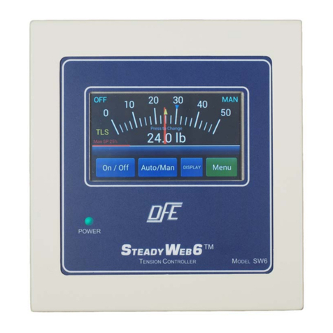
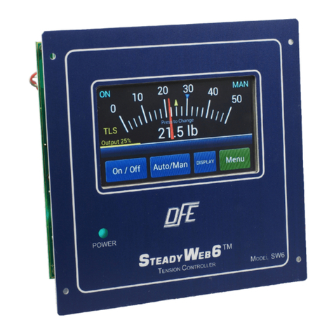
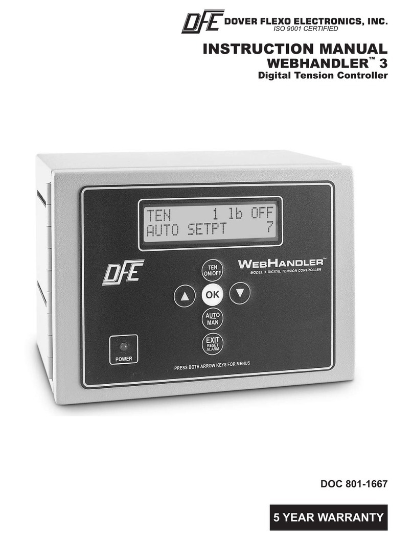
DFE SteadyWeb User manual

INSTRUCTION MANUAL
STEADYWEB™
AUTOMATIC TENSION CONTROLLER
DOC 801-0783

217 Pickering Road
Rochester, NH 03867-4630 U.S.A.
For assistance, please call:
TECHNICAL SERVICE - Installations, Start-Up, Troubleshooting, Repairs, Field
Service, Returns: call 603-332-6150 and ask for Technical
CUSTOMER SERVICE - Replacement Parts, Individual Products, Questions about
Orders, Manuals: call 603-332-6150 and ask for Customer
SALES - Product Information, Systems Application Questions, and
placing orders for standard products and special systems.
Please call 603-332-6150 and ask for Sales or email to us at
Telephone: (603) 332-6150 Fax: (603) 332-3758
©1999 Dover Flexo Electronics, Inc. All rights reserved. Dover Flexo Electronics has made reasonable effort to ensure accuracy of this document.
However NO WARRANTY, whether expressed or implied, is given regarding the completeness or correctness of information in this document.
Dover Flexo Electronics shall not be liable for damages of any kind arising from the use or misuse of this document. Dover Flexo Electronics
reserves the right to make changes, additions, and deletions to this document without notice and without obligation.

READ THIS!
Your SteadyWeb™Controller has been properly configured at our factory. To install
it and start it up, it should only be necessary to use these sections of this manual:
Section 2 - Installation
Section 4 - Calibration the Tension Meter
Section 7 - Tuning for Running Stability
The other sections are for reference and for instruction if you wish to change the
configuration at some later time.

TABLE OF CONTENTS
SECTION ONE DESCRIPTION PAGE
1.0 General Description 1
1.1 Output Modules, Version of Controller 1
Pneumatic Output Module (12P) 1
High Voltage Output Module (12V) 1
0-10 Volt Compensated Output Module (12D) 1
1.2 SteadyWeb Controller Exploded View 2
1.3 Specifications 3
1.4 Standard Features
0-10 Volt Tension Output 4
4-20mA Tension Output 4
Automatic Control Mode 4
Control Voltage Selection 4
Emergency Stop 4
Manual Control Mode 4
Meter Correlation Adjustment 4
Meter Damping 4
Output Direction Selection (normal/reverse) 4
Output Meter 4
Power Voltage Selection 4
Ratio 5
Remote Tension On/Off 5
Remote Tension Set 5
Sample & Hold 5
Soft Start 5
Speed Follow 5
Speed Match 5
Status Lights 5
Tension Display 5
Transducer Voltage Selection 5
1.5 Options
220 Volt Power 6
24 Volt Output 6
45 Volt Output 6
Chassis Configuration (CC) 6
DC Tahometer Card 6
Digital Meter 6
Dual Calibration 6
Dual Transducer Input 6
Extended Range 6
Metric Air Tubing 6
Nonstandard Meter Scale 6
Pulse Tachometer Card 6
Remote Operator Devices (H6) 7
Remote Pneumatic Module 7
Remote Tension Amplifier 7
Reverse Output 7
Taper Adjustment on Front Panel 7
Taper Tension 7
Tension Limit Switch 7
1.6 Front Panel & Operator Devices 8

SECTION TWO INSTALLATION OF STANDARD UNIT
2.0 Dimensions 9
2.1 Installing the Enclosure 10
2.2 Electrical Connections 11
2.3 Electrical Connections for Options 12
SECTION THREE INSTALLATION OF H6 AND CC
CONFIGURATIONS
3.0 H6 Configuration 13
Dimensions 14
3.1 CC Configuration 15
Dimensions 15
Electrical Connections 16
SECTION FOUR CALIBRATING THE TENSION METER
4.0 Mechanical Zero 18
4.1 Calibration 18
SECTION FIVE SET-UP AND ADJUSTMENTS OF
STANDARD UNIT
5.0 Tension Zones 20
5.1 The Control Board 21
5.2 The Power Board 22
5.3 Power Voltage Selection 23
5.4 Control Voltage Selection 23
5.5 4-20mA or 0-20mA Output 24
5.6 Emergency Stop 25
5.7 High Voltage Output Module (12V only) 26
5.8 Meter Correlation 27
5.9 Meter Damping 27
5.10 Output Direction 27
5.11 Output Meter 28
5.12 Pneumatic Output Module (12P only) 28
5.13 Ratio Up/Down 29
5.14 Remote Tension Amplifier Installed? 30
5.15 Remote Tension On/Off 30
5.16 Remote Tension Set 30
5.17 Sample and Hold 31
5.18 Soft Start 31
5.19 Speed Follow 33
5.20 Tachometer Card Installed? 34
5.21 TLS Card Installed? 34
5.22 Transducer Voltage Selection 34
SECTION SIX SET-UP AND ADJUSTMENTS OF OPTIONS
6.0 220 Volt Power Input 36
6.1 24 Volt Output 36
6.2 45 Volt Output 36
6.3 DC Tachometer Card 36
6.4 Digital Meter 38
6.5 Dual Calibration 40
6.6 Dual Transducer Input 40
6.7 Extended Range 40
6.8 Pulse Tachometer Card 40
6.9 Remote Tension Amplifier 42
6.10 Taper Adjustment of Front Panel 43

6.11 Taper Tension 43
Taper by Diameter Computer 43
Taper by Rider Roll or Voltage Source 44
6.12 Tension Limit Switch (TLS) 46
SECTION SEVEN TUNING FOR RUNNING STABILITY
7.0 Introduction 49
7.1 Description of Adjustments 49
7.2 Tuning Procedure 50
7.3 Tuning the Speed Follow Function 50
SECTION EIGHT REPLACEMENT PARTS
8.0 Standard Circuit Boards 52
8.1 Optional Circuit Boards 52
8.2 Operator Devices 52
8.3 Output Modules 52
8.4 Fuses 52
8.5 Ribbon Cables 52
8.6 Relays 53
8.7 Miscellaneous 53
APPENDICES
ALocations of Standard Adjustments 54
BDIP Switch Settings 55
CBasic Set-up 58
DElectrical Connections of Standard SteadyWeb 60
EElectrical Connections of Options 61
FTransducer Electrical Connections 62
GTypical Tensions 66
HFront Board 67
ITroubleshooting 68
TERMS AND CONDITIONS OF SALE 69
INDEX 70,71

LIST OF ILLUSTRATIONS
FIGURE DESCRIPTION PAGE
1 SteadyWeb Controller - Exploded View 2
2 Front Panel and Operator Devices 8
3 Dimensions 9
4 Mounting Screw Locations 10
5 Cover Removal 10
6 Electrical Connections 11
7 Electrical Connections of Options 12
8 Remote Operator Device Configuration 13
9 Dimensions of H6 14
10 Chassis Configuration (CC) 15
11 Dimensions of CC Configuration 15
12 Electrical Connections of CC 16,17
13 Meter Access Holes 18
14 Web Path for Meter Calibration 19
15 Tension Zones 20
16 Control Board 21
17 Power Board 22
18 Power Switch 23
19 E-Stop Electrical Connections 25
20 V-OUT Module 26
21 Ratio Contact Electrical Connections 29
22 Remote Tension On/Off Button Connections 30
23 Sample & Hold Contact 31
24 Soft Start Connections 32
25 Transducer Voltage Switch 35
26 DC Tach Option Card 36
27 DC Tachometer Connections 37
28 Digital Meter Display 39
29 Digital Meter Card 39
30 Pulse Tach Option Card 41
31 Pulse tachometer Connections 41
32 Remote Tension Amplifier Electrical Connections 43
33 Taper Dia/Calc Option Card 43
34 Taper RIDER Option Card 45
35 Rider Pot. Connections 45
36 10 Volt Source Connections 45
37 TLS Option Card 46
38 TLS Reset Button Connections 47
39 TLS Relay Connections 48
40 Tuning Pots. 49
41 Standard Adjustments - Control Board 54
42 Standard Adjustments - Power Board 54
43 Standard Electrical Connections 60
44 Optional Electrical Connections 61
45 Model C, UPB Transducer Wiring 62
46 RF Transducer Wiring 63
47 TR, NW Transducer Wiring 64
48 LT Transducer Wiring 65
49 Front Board 67


1
SECTION 1 DESCRIPTION
1.0 GENERAL DESCRIPTION
The SteadyWeb tension controller automatically maintains tension of any continuous material at the
value selected by the machine operator. It consists of three basic functions:
The first function is performed by the tension amplifier. It supports all of Dover Flexo Electronics
tension transducers. (The transducers measure the actual tension in the web). It includes a regulated
power supply to excite the transducers, an amplifier to boost the transducer output signal, and a
calibration circuit to adjust the tension readout to display actual tension.
The second function is the tension regulator. It compares the output signal from the transducers with
the signal from the AUTO Set potentiometer on the front of the SteadyWeb enclosure. If there is a
difference, the regulator will either increase or decrease tension to equalize them. The tension
amplifier and the tension regulator are both located on the Control board. (See Figure 1)
The third function is performed by the output module. It accepts the output from the tension regulator
and actuates a brake, clutch, or variable speed drive system which actually creates the tension in the
web.
1.1 OUTPUT MODULES, VERSION OF CONTROLLER
Three output modules are available for the SteadyWeb controller.
A) Pneumatic output module. This is used to actuate any air operated brake or clutch. It includes a
servo valve, a pressure regulator, and an air filter. These items are fitted together into a compact
assembly which is normally installed inside the controller enclosure or optionally located remotely.
The output range is .5 to 75 psi. SteadyWeb controllers having this module are designated
"Version 12P".
B) High Voltage output module. This module uses SCR's to produce a variable voltage of up to 90
volts DC to operate any electric brake or clutch, including eddy current clutches. 45 volt and 24 volt
outputs are optional. This module is also known as the VOUT Card. SteadyWeb controllers having
this output module are designated "Version 12V".
C)0 to 10 Volt DC compensated output module. This module is in the form of a 16 pin DIP Integrated
Circuit that plugs into the Power board near the top center. It is designated U203. See Figure 17.
This output is used to control DC drives or other variable speed drive systems, usually in
intermediate tension zones. This output is isolated from ground to make it compatible with all
drives. SteadyWeb controllers having this output are designated "Version 12D".
All SteadyWeb controllers may be easily converted from one output to another if desired. There are
five locations for plug-in cards for optional features, three on the Control board and two on the
Power board. See Figures 16, 17.

2
1.2 STEADYWEB CONTROLLER EXPLODED VIEW
Figure 1 - STEADYWEB CONTROLLER - EXPLODED VIEW

3
1.3 SPECIFICATIONS
POWER INPUT 12P and 12D ..... 120/240 Volts 60/50Hz single phase @ 1 Amp
12V ............ 120/240 Volts 60/50Hz single phase @ 5 Amp
OUTPUT 12P ............ 0.5to75psi(,03to5,17bar)
12V ............ 90VoltsDC,45VDC,24VDC,all@4Amp
............ 180VDC @4 Amp and 230VAC Input
12D ............ 0-10VoltsDC,compensated and isolated
TENSIONSIGNALOUTPUT .......... 0-10VoltsDC
........... 4-20MAinto500 ohm maximum load
ENCLOSURE ............ Steel,powderresinpainted,NEMA1
WEIGHT ............ 26lbs.(11,8KG)
AIRCONNECTIONS:12PIn .......... 3/8inchplastictubing(5/16",8mmoptional)
Out......... 1/4inchplastictubing(6mm)
INTERNALAIRFILTER 12P......... 5micron,1/2pintbowl,automaticdrain
TRANSDUCER SIGNAL ............ 500 mv DC per pair at rated load, 1.0 Volt with
........... Extended Range option
MATING TRANSDUCER CABLE
CONNECTORS ............ Amphenol MS3106A-10SL-3S
ZERO(TARE)RANGE ............ 95%oftransducerrating,minimum
CALIBRATIONRANGE ............ 25:1
TEMPERATURERANGE ............ 32to104 deg.F (0-40 deg.C)
SYSTEM ACCURACY ............ 1-3%typical
TENSIONMETER ............ Analog,2%,1ma,48ohm
OUTPUTRANGE ............ 0-100% Max., Min. = 0-20% of Max.
MANUALMODEOUTPUTRANGE..... 0-100%
OUTPUTRATIORANGES ........... 1:10(multiplier)and 10:1(divider)
STANDARD TENSION METER SCALES 0 - 1,5,10,25,50,100,150,250,500,1000
TENSION LIMIT SWITCH RELAY
CONTACTS(option) ............ SPDTrated@10A/30VDC,10A/250VAC
TAPER TENSION RANGE (option) ..... 0-100%
TAPER TENSION INPUTS (option)
Code TTDCT (using DC Tachs) . . . Switch selected, 3V to 250V
Code TTPT (using Pulse Tachs) . . . 300Hz to 40KHz at max. line speed
Code TTF (Roll Follower) ........ 10Kohmpot.minimum
Code TTR (external voltage) ...... 0-10VDCcoretofullroll

4
1.4 STANDARD FEATURES
SOME OF THESE FUNCTIONS REQUIRE CONFIGURING OR EXTERNAL WIRING. REFER TO
SECTION 5 FOR CONFIGURING AND SECTION 2.2 FOR WIRING.
!0-10 VOLT DC TENSION OUT. Proportional to web tension. Used as an input to other control
systems, computers or data collection devices.
!4-20mA TENSION OUT. Proportional to web tension. Used as an input to other control systems,
computers or data collection devices.
!AUTOMATIC CONTROL MODE. The controller output is determined by the difference between
web tension and the AUTO tension set knob position. The internal regulator automatically varies
the output as required to maintain set tension.
!CONTROL VOLTAGE SELECTION. Choose one of three available Control board outputs. They
are 0 to +10 VDC, 0 to -10VDC, and -10 to +10VDC. The 0 to +10VDC output operates pneumatic
(12P) and high voltage (12V) output modules when used. Any of the three outputs can be used in
the 12D version of the SteadyWeb.
!EMERGENCY STOP. Controller immediately goes to full output or zero output (selectable) upon
closure of an external contact. Normally full output is used on unwinds to stop the roll of material
quickly. Zero output is used for rewind or intermediate controllers.
!MANUAL CONTROL MODE. The controller output is determined only by the position of the
MANUAL set knob. No change occurs unless the knob is turned. Used during machine set-up or
during trouble-shooting.
!METER CORRELATION ADJUSTMENT. This causes the position of the AUTO set pot. to
correspond to the position of the needle on the analog tension meter. For example; if the AUTO
pot. is set at 4 on its dial, the tension meter would read 40% of full scale. This is important for the
proper operation of the controller.
!METER DAMPING. Eliminates vibration of the analog tension meter needle. Also minimizes flicker
of the optional digital meter.
!OUTPUT DIRECTION. Select between Normal and Reverse output. Most applications use the
Normal selection, controller output goes up when tension falls below the set level. The Reverse
selection causes output to go down when tension falls below the set level. It is used in intermediate
tension zones where the transducers are located after the nip rolls they control, and for driven
unwinds.
!OUTPUT METER. Displays the controller output, measured in 0 to 100 percent. Set 0 at left end
of scale for Version 12P, 12V and some 12D controllers. Or Set 0 at center of scale when using an
optional center-zero meter for Version 12D controllers having -10 to +10 volt outputs.
!POWER VOLTAGE SELECTION. The SteadyWeb controller is designed to operate on two ranges
of AC power; 110-120 Volts 60/50 Hz, and 220-240 Volts 60/50 Hz. A slide switch on the Power
board selects between the two.

5
!RATIO. Takes the sampled output and multiplies it (unwind applications) or divides it (rewind
applications) by a factor adjustable between 1 and 10. Used in flying splice applications to help
provide a match between controller output and roll diameter.
!REMOTE TENSION ON/OFF. Requires two momentary pushbuttons supplied by customer and
located external to the controller. Enables the machine operator to turn the controller output on and
off at the remote location and at the controller.
!REMOTE TENSION SET. Locate an AUTO Tension Set potentiometer external to the controller in
addition to the one on the front panel of the controller. Select between the two with a switch inside
the controller. Only one pot. can be active at any one time.
!SAMPLE AND HOLD. Locks the controller output at whatever level it may be when an external
contact closes, and maintains it there until the contact opens. Usually used in flying splice
applications to prevent instability during the splice. Also actuated by the RATIO function.
!SOFT START. Used on unwinds. Actuated either automatically upon a loss of tension below the
preset trip point (after an adjustable delay), immediately upon an external contact closure, or by
machine speed. Controller output is reduced to a preset low level to prevent brake lock-up when
the machine starts. When tension rises above the trip point, the controller goes back to the
automatic control mode. Does not operate in the MANUAL control mode. Actuation by machine
speed requires an optional Tachometer Card (see Options, Section 1.5)
!SPEED FOLLOW. This is a special function normally used on Version 12D SteadyWebs controlling
tension in an intermediate zone (see Tension Zone drawing, Section 5.0, page 20) or surface
driven rewinds and unwinds. Versions 12P and 12V can also use it if they are controlling a clutch
which has a constant input speed. In any case, the controller must be equipped with an optional
DC Tach card or Pulse Tach card.
The Control board contains a regulator circuit, separate from the tension regulator, that accepts a
line speed signal and, optionally, a nip roll speed signal. The line speed signal causes the output of
the controller to follow (go up and down with) line speed. The output of the tension regulator then
trims the follower output as needed to maintain set tension.
The follower method described above is recommended over the Speed Match method for most
applications because it is less affected by tachometer drift, is easier to set up and its adjustment is
less critical, and will not result in a run-away condition if the nip roll speed signal is lost.
!SPEED MATCH. The same as Speed Follow above, except that the nip roll speed input is also
used. In this case, the nip roll is speed-regulated and the tension regulator trims the roll speed.
!STATUS LIGHTS. Show that particular functions are active when lights are illuminated.
!TENSION DISPLAY. Web tension is displayed on an analog meter which is calibrated to read out
total tension in pounds, newtons, kilograms, or any other desired units. A digital meter is optional.
!TRANSDUCER VOLTAGE SELECTION. Choose between 5VDC and 10VDC excitation for the
tension transducers. 5VDC is standard. 10VDC is used only for the extended range option.

6
1.5 OPTIONS (The option code is shown in parentheses)
SOME OF THESE OPTIONAL FUNCTIONS REQUIRE CONFIGURING OR EXTERNAL WIRING.
REFER TO SECTION 6 FOR CONFIGURING AND SECTION 2.3 FOR WIRING.
!220 VOLT POWER (220V). 220 volt 50/60 Hz power input.
!24 VOLT OUTPUT (24V). For Version 12V only. Factory-installed option with 220V power.
!45 VOLT OUTPUT (45V). For Version 12V only.
!CHASSIS CONFIGURATION (CC). No cover or front panel on enclosure. Customer supplies all
operator devices. Controller must be installed inside customer's enclosure.
!DC TACHOMETER CARD (DCT). Takes the voltage output from one or two DC tachometers and
scales it to 0-10 volts DC. This card is required for the Taper Tension (TTDCT) option, the version
of Soft Start which is actuated by machine speed, and the Speed Follow function. This card plugs
into the Power Board.
!DIGITAL METER (DM). 4 full digits, red 1" high LED's with over and under range indicators. The
maximum range is 0000 to 9999. An over-range indicator lights at values over 9999, and an under-
range indicator lights at values below 0. Can be read from further away than the analog meter. Up
to 2 decimal places.
!DUAL CALIBRATION (DC). Two meter scales for the standard analog tension meter and/or two
running-stability setups. The meter scales may have any ratio, limited only by the range of the
transducers. Used in those cases in which a wide range of materials having very wide tension
requirements are being run.
!DUAL TRANSDUCER INPUT (DTI). Controller receives two separate tension signals, one from
each of two sets of transducers. Used when a very wide range of tensions must be controlled. A
switch on the front panel selects the tension signal to use. The option card plugs into the left-hand
option socket on the Power board. There are no adjustments on this card. The Dual Calibration
option (DC) is required.
!EXTENDED RANGE (XR). The transducers are excited by 10 volts instead of the standard 5 volts.
Used for low tension applications. The transducers must also have the XR option.
!METRIC AIR TUBING (8MM). For Version 12P only. Air fitting for use of 8mm diameter air supply
tubing in place of the standard 3/8 inch tubing.
!NONSTANDARD METER SCALE (NMS). Any nonstandard analog meter scale. Either single or
dual scale. See Specifications, page 3, for standard scales.
!PULSE TACHOMETER CARD (PT). Takes the pulse output from one or two rotary encoders, AC
tachometers or other types of pulse generators and converts and scales it to 0-10 volts DC. This
card is required for the Taper Tension (TTPT) option, the version of Soft Start which is actuated by
machine speed, and the Speed Follow function. This card plugs into the Power Board.

7
!REMOTE OPERATOR DEVICES (H6). No cover on enclosure. Front panel attached to controller
via a 6'(length optional) cable. Allows front panel to be installed in customer's control panel and
controller to be installed inside.
!REMOTE PNEUMATIC MODULE (2E). For Version 12P only. Allows servo valve to be installed
close to the brake/clutch while the controller is located elsewhere.
!REMOTE TENSION AMPLIFIER (RTA). The internal tension amplifier is bypassed and the tension
signal is provided by an external remote device such as the TI7. This allows use of special
indicator functions, such as intrinsic safety, which are not available in the SteadyWeb controller.
!REVERSE OUTPUT (RO). Controller output goes up when tension exceeds the set point. This is
the reverse of normal, when output goes down upon excess tension. Used in intermediate tension
zones where the transducers are located after the nip rolls they control. NOTE: No additional
wiring connections or components are needed to use the Reverse Output feature. It is selected by
a switch on the Control board. See section 5.10 for setup.
!TAPER ADJUSTMENT ON FRONT PANEL (XTA). Instead of inside controller.
!TAPER TENSION. For rewind applications. Causes tension to decrease as roll diameter
increases. Helps produce a better quality roll by eliminating telescoping, crushed cores, too tight or
too loose rolls. Two methods are available, diameter computer and rider roll. The diameter
computer method requires machine speed and roll speed signals from the optional DC Tachometer
Card or the Pulse Tachometer Card. The rider roll method requires a follower roll in contact with
the rewinding roll, or some other roll-sensing device such as a sonic rangefinder to detect the roll
diameter. The device must have a 0-10 Volt DC output. Taper is adjustable from 0 to 100%. The
taper circuitry is located on a card which is plugged into the Control Board. Here is a list of the
different types of taper circuits available:
(TTDCT) DC Tachometers used for speed signals.
(TTPT) Pulse Tach generators used for speed signals.
(TTF) Roll Follower or external 0-10VDC source used.
!TENSION LIMIT SWITCH (TLS). Provides relay contact closure at preset tension levels,
either high or low. Usually used as a web break detector. The electronic circuitry is located
on a card which is plugged into the Control Board. The relay is located on the Power
Board.

8
1.6 FRONT PANEL AND OPERATOR DEVICES
Figure 2 - FRONT PANEL and OPERATOR DEVICES

9
SECTION 2 INSTALLATION
2.0 DIMENSIONS
ABCDEFGHJKL
inch 12.44 10.42 7.75 1.42 2.41 .24 11.78 9.41 10.54 4.71 .42
mm 316 265 197 36 61 6 299 239 268 120 11
Note: Allow 5" (127mm) clearance on the left side for the controller to open completely.
FRONT SIDE BACK
REMOTE PNEUMATIC ASSEMBLY DIMENSIONS
ABCDEFG
inch 2.0 4.5 8.0 3.0 6.0 2.0 .56
mm 51 114 203 76 152 51 14
Figure 3 - DIMENSIONS

10
2.1 INSTALLING THE ENCLOSURE
Select a location on the machine frame or a wall that will be convenient for the machine
operator to operate the controller and to see the tension meter easily. Be sure the location is
free of vibration, and is dry and clean. Take care to choose a place that the controller won't
be struck and damaged by anything or anyone.
The enclosure is fastened to the mounting surface you have chosen by two socket head cap
screws. Install the screws in the mounting surface as shown below. Leave them loose about
6 turns. Position the keyholes in the back panel of the enclosure over the screws and slide it
down until it locks in place. The cover must be removed to tighten the mounting screws. (See
Figure 5)
Figure 4 - MOUNTING SCREW LOCATIONS
Figure 5 - COVER REMOVAL

11
After removing the cover, swing the front panel out by first loosening the two screws on the right side
top and bottom corners 1/4 turn CCW. Use a hex wrench to tighten the two enclosure mounting
screws.
2.2 ELECTRICAL CONNECTIONS
Refer to the drawing below for electrical connections. If your controller has any optional equipment,
refer to Section 2.3 or Appendix D of this manual for the appropriate connections. TB201, TB203 and
TB204 are located on the Power Board.
Figure 6 - ELECTRICAL CONNECTIONS
NOTE: The tension transducers are usually connected to the controller by two 3 pin Amphenol
connectors mounted on the bottom of the enclosure. However they may be hard-wired
directly to the terminal strips as shown above, if desired.

12
2.3 ELECTRICAL CONNECTIONS OF OPTIONS
Figure 7 - ELECTRICAL CONNECTIONS OF OPTIONS
Table of contents
Other DFE Controllers manuals
Popular Controllers manuals by other brands
Jands
Jands SafeGuard installation guide
IFM Electronic
IFM Electronic ecomat 100 R 360 Mounting and installation instructions
Emerson
Emerson Bettis RTS FQ Series operating manual
BACHMANN EUROPE Plc
BACHMANN EUROPE Plc 36-565 operating instructions
inVENTer
inVENTer iV14-Zero sMove operating instructions
Beckett
Beckett AquaSmart manual
