Table of Contents
Copyright�������������������������������������������������������������������������������������������������������������2
Trademarks ��������������������������������������������������������������������������������������������������������2
FCC and DOC Statement on Class A����������������������������������������������������� 2
About this Manual ������������������������������������������������������������������������������������������4
Warranty��������������������������������������������������������������������������������������������������������������4
Static Electricity Precautions����������������������������������������������������������������������4
Safety Measures ����������������������������������������������������������������������������������������������4
Safety Precautions������������������������������������������������������������������������������������������5
About the Package�����������������������������������������������������������������������������������������5
Chapter 1 - Introduction �����������������������������������������������������������������������������6
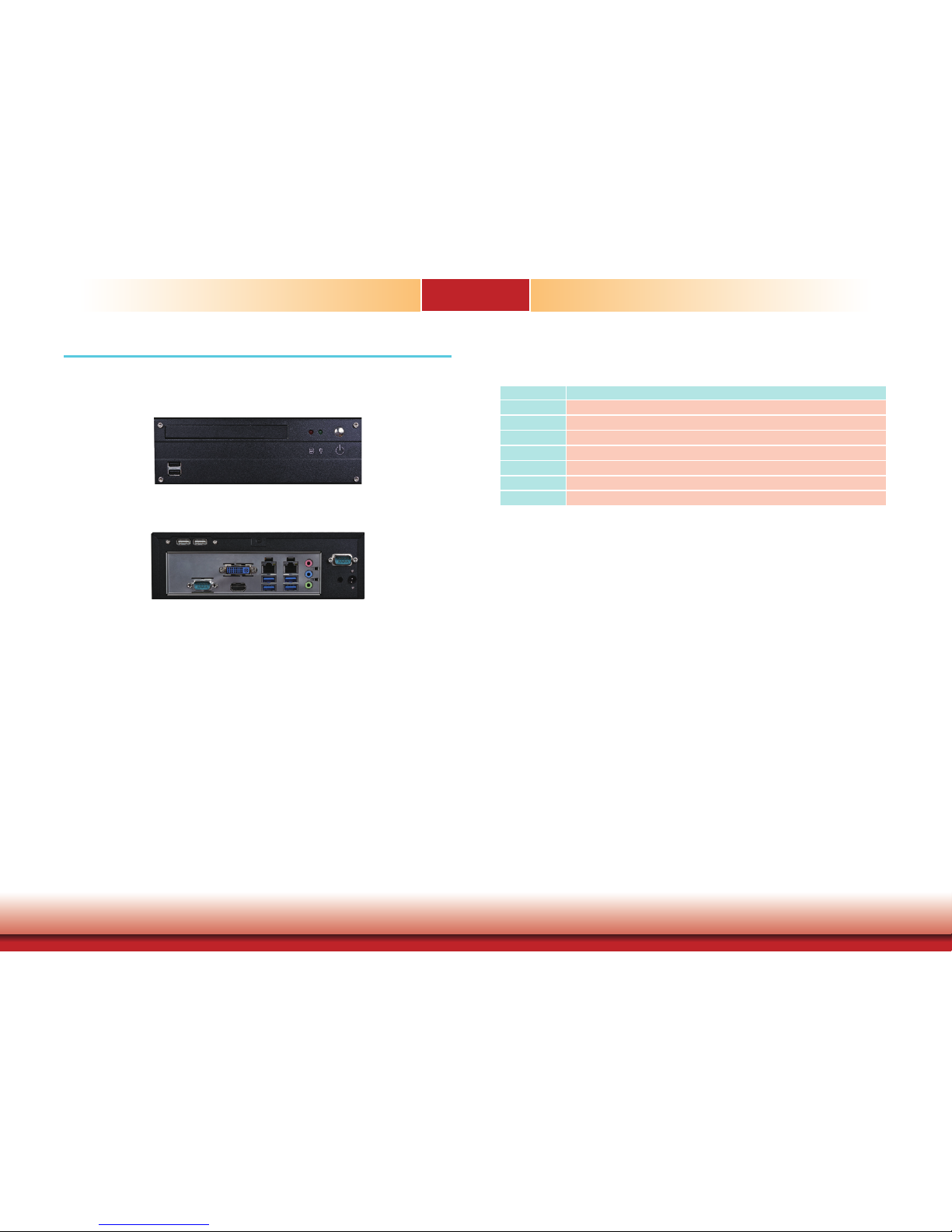
Overview �������������������������������������������������������������������������������������������������������6
Key Features ������������������������������������������������������������������������������������������������ 6
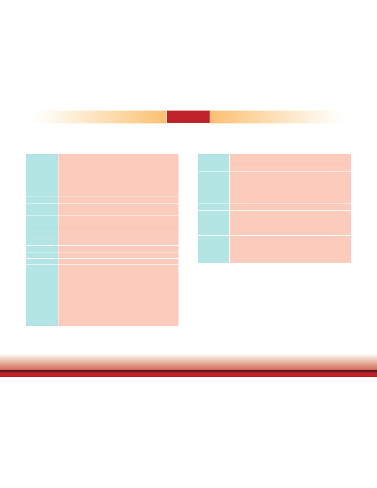
Specifications �����������������������������������������������������������������������������������������������7
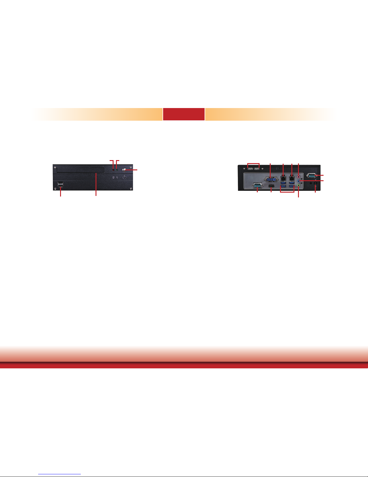
Getting the Know the ST101-CR �����������������������������������������������������������8
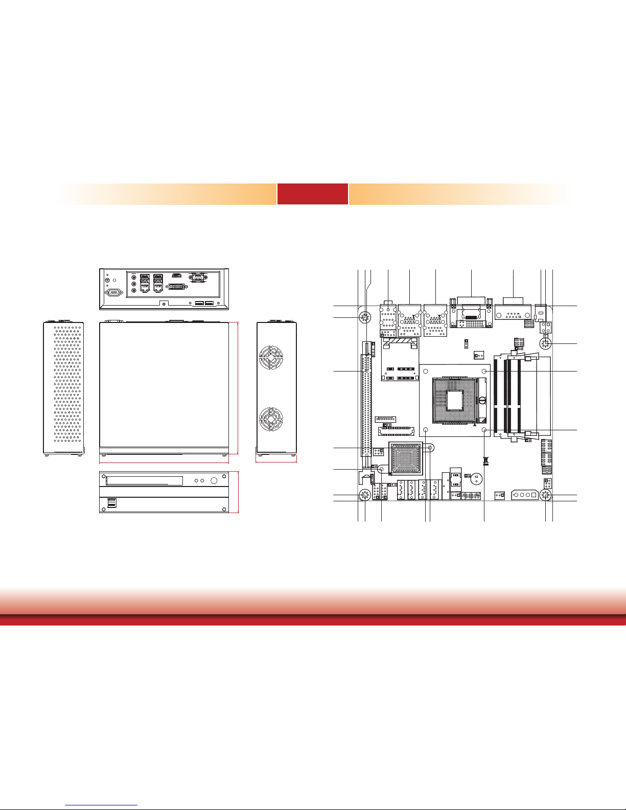
Mechanical Dimensions ����������������������������������������������������������������������������� 9
Chapter 2 - Getting Started �������������������������������������������������������� 10
Preparing the system ������������������������������������������������������������������������������ 10
Installing Devices ������������������������������������������������������������������������������������� 10
Configuring the BIOS ������������������������������������������������������������������������������ 10
Installing the Operating System ���������������������������������������������������������� 10
Installing the Drivers ������������������������������������������������������������������������������� 10
Chapter 3 - Installing Devices ���������������������������������������������������� 11
Removing the Chassis Cover ����������������������������������������������������������������� 11
Removing the Drive Bay ������������������������������������������������������������������������ 11
Installing the SATA and Optical Drive Bays �������������������������������������� 12
Chapter 4 - Jumper Settings������������������������������������������������������� 16
Clear CMOS ������������������������������������������������������������������������������������������������ 16
USB Power Select ������������������������������������������������������������������������������������� 16
Panel Power Select ���������������������������������������������������������������������������������� 17
COM1/ COM2 RS232/422/485 Select ������������������������������������������������� 17
COM1/ COM2 RS232 Power Select ����������������������������������������������������� 18
COM1 Signal Select ��������������������������������������������������������������������������������� 18
Power-On Select ��������������������������������������������������������������������������������������� 19
Backlight Level Select ����������������������������������������������������������������������������� 19
Switch ���������������������������������������������������������������������������������������������������������� 20
Chapter 5 - Ports and Connectors���������������������������������������������� 21
Front Panel I/O Ports ������������������������������������������������������������������������������ 21
USB Ports ������������������������������������������������������������������������������������������������� 21
Rear Panel I/O Ports ������������������������������������������������������������������������������� 22
DC-in �������������������������������������������������������������������������������������������������������� 22
COM (Serial) Ports ������������������������������������������������������������������������������������� 23
Graphics Interface ������������������������������������������������������������������������������������� 23
RJ45 LAN Ports ����������������������������������������������������������������������������������������� 24
USB Ports ������������������������������������������������������������������������������������������������� 24
Audio �������������������������������������������������������������������������������������������������������� 25
I/O Connectors ������������������������������������������������������������������������������������������ 26
S/PDIF Connector �������������������������������������������������������������������������������������� 26
SATA (Serial ATA) Connectors ��������������������������������������������������������������������� 26
LVDS LCD Panel Connectors ����������������������������������������������������������������������� 27
Chassis Instrusion Connector ��������������������������������������������������������������������� 28
Cooling Fan Connectors ����������������������������������������������������������������������������� 28
Standby Power LED ����������������������������������������������������������������������������������� 29
Power Connectors ������������������������������������������������������������������������������������� 29
Front Panel Connectors ������������������������������������������������������������������������������ 30
Peripheral Power ��������������������������������������������������������������������������������������� 30
LPC connector ������������������������������������������������������������������������������������������� 31
Expansion Slots ����������������������������������������������������������������������������������������� 31
Battery ����������������������������������������������������������������������������������������������������� 32
Chapter 6 - Mounting Options �������������������������������������������������������������� 33
Wall Mount ������������������������������������������������������������������������������������������������� 33
Chapter 7 - BIOS Setup ������������������������������������������������������������� 35
Overview ����������������������������������������������������������������������������������������������������� 35
AMI BIOS Setup Utility����������������������������������������������������������������������������� 36
Main ���������������������������������������������������������������������������������������������������������� 36
Advanced ��������������������������������������������������������������������������������������������������� 36
Chipset ������������������������������������������������������������������������������������������������������ 44
Boot����������������������������������������������������������������������������������������������������������� 48
Security������������������������������������������������������������������������������������������������������ 50
Save & Exit ����������������������������������������������������������������������������������������������� 50
Updating the BIOS ��������������������������������������������������������������������������������������� 51
Chapter 8 - Supported Software ���������������������������������������������������������� 52
Appendix A - nLite and AHCI Installation Guide ������������������������� 65
Appendix B - Watchdog Sample Code ���������������������������������������������� 71
Appendix C - System Error Message ������������������������������������������������� 72
Appendix D - Troubleshooting �������������������������������������������������������������� 73