manuals.online logo
Brands
  1. Home
  2. •
  3. Brands
  4. •
  5. DFI
  6. •
  7. Desktop
  8. •
  9. DFI EC533-KD-AI6881 User manual

DFI EC533-KD-AI6881 User manual

1
www.dfi.com
DFI reserves the right to change the specications at any time prior to the product's release. For
the latest revision of related technical documents and further information, please refer to related
technical docs on our website at go.d.com/EC533-KD-AI or scan the QR code on the right.
Package Contents
Quick Installation Guide
EC533-KD-AI6881/3G46E
•
1 EC533-KD-AI6881 System Unit
• 1 Quick Installation Guide
•
Mounting Screws for Mini PCIe and M.2
Front View
Notes:
1. This port can be in DVI-D or HDMI (HDMI available upon request).
2. This port is a DP/HDMI combo port but can only transmit HDMI signals (unless wired as a DP port).
Please plug in a DP or an HDMI cable with the right orientation and alignment to avoid damage
to the connector. You should feel resistance (due to a pin on the right) if the cable is not inserted
correctly. For detailed instructions, see https://youtu.be/SUj07rfN5l8.
Align this edge with the
left side of the connector
Angled-corner
(up)
Angled-corner
Aligning side
(left) pin
DC-in
DVI-I(1)
(DVI-D signal)
HDMI
(2)
USB 3.0
LAN 1
LAN 2
USB 3.0
SATA 1
SATA 2
COM3
COM2 (/power)
COM1 (/power)
VGA
Mic-in Line-out
Expansion
slots
COM6
COM5
(/power)
COM4
(/power)
DIO
Graphics Card Power
Power button
Status/HDD
Reset
Remote
power on/off
RS232
(/power)
12 3 45
6789
DCD
(or +12V)
TXD
RXD
DTR
GND
RTS
RI
(or +5V)
DSR
CTS
245
3
1
7
689
245
3
1
7
6 8 9
DIO_0
DIO_1
DIO_2
DIO_3
GND
(or DIO_4)
(or DIO_5)
(or DIO_6)
(or DIO_7)
DATA+
DATA-
N.C.
N.C.
GND
N.C.
N.C.
N.C.
N.C.
DIO RS422
Full Duplex RS485
6 7 8 9
RXD+
TXD+
RXD-
TXD-
N.C.
12 3 45
N.C.
N.C.
N.C.
N.C.
AI6881 3G46E
DC-in
DVI-I(1)
(DVI-D signal)
HDMI
(2)
USB 3.0
LAN 1
LAN 2
SATA 1
SATA 2
Remote power
on/off
Line-out
Mic-in
Expansion slots
PoE 1~4
DIO
Graphics Card Power
Power button
Status/HDD
Reset
COM3
COM2 (/power)
COM1 (/power)
VGA
2
Quick Installation Guide |
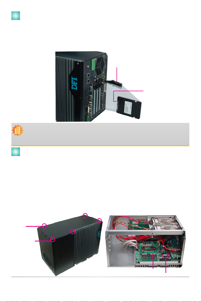
Installing a 2.5" SATA Drive
The SATA drive bay can be easily accessed witout opening the system. However, the system
does not support hot-swapping hard drives; turn off the system rst before proceeding with the
following procedure for installing a SATA drive. Locate the drive bay on the front panel and open it
by releasing the handle. Slide the HDD into the drive bay. Note that the HDD should be positioned
vertically with the SATA data connector on top of the power connector to correctly engage with the
system's SATA connectors. Then close the drive bay and lock the handle.
Notes:
1. The slot is desgined to exactly t a 2.5" SATA drive with 7mm thickness; it cannot t
SATA drives with other sizes.
2.
Do not force to close the drive bay if the HDD is not correctly inserted.
Removing the Chassis Cover
Please observe the following guidelines and follow the procedure to open the system.
1. Service or maintenance procedures should only be performed by trained technicians.
2. Ground yourself by using a wrist grounding strap to prevent electrostatic discharge.
3. Make sure the connected system or computer and all other devices connected to it have been
powered off.
4. Disconnect all power cords and cables.
5. The 5 mounting screws on the top cover of the system are used to secure the cover to the
chassis. Remove these screws and then put them in a safe place for later use.
6. After removing the mounting screws, lift the chassis cover to open the system.
SATA data Connecotr
Drive bay handle
Mounting screw
SODIMM sockets
Mini PCIe sockets
3
Installing Devices
Installing a SODIMM
Installing a Mini PCIe Card
The system board is equipped with 2 Mini PCIe
slots: full-size (black) and half-size (white). The
half-size slot provides USB & SATA interfaces
whereas the full-size slot provides PCIe and USB
interfaces.
The system supports two DDR4
SODIMM sockets (dual channel).
Installing a PCIe Expansion Card
Important:
When inserting expansion cards into the system unit, please select a standard card
within 303x126x41 (LxWxH) mm in order to t into the system chassis.
Note: The EC532-KD-AI6881 provides one PCIe x16 and one PCIe x4 (x 1 lane)
expansion slots with the H320-2E riser card. The EC533-KD-AI6881 and EC533-KD-
AI3G46E one PCIe x16 and two PCIe x4 (x 1 lane) slots with the H320-3E riser card.
To install an expansion card, you need to rst remove the slot plates and bracket by uninstalling the
thumb screws on the front panel.
Mini PCIe Module Mini PCIe Socket
Key
Stand-off
Notch
Mini PCIe Module Mini PCIe Socket
Key
Stand-off
Notch
Mini PCIe Module Mini PCIe Socket
Key
Stand-off
Notch
Step 1
Step 2
Step 3
Notch
Retention Notch
Key
Socket Top View
DDR4 SO-DIMM
Retention Clip
45°
Step 1
Step 2
Step 3
Notch
Retention Notch
Key
Socket Top View
DDR4 SO-DIMM
Retention Clip
45°
Step 1
Step 2
Step 3
Step 1
Step 2
Step 3
thumbscrew
and bracket
Slot plate
PCIe cardPCIe expansion slot
8-pin graphics card
power connector
4
Quick Installation Guide |
1
6
(JP7)
1
6
(JP2)
1
6
(JP3) 1
6
(JP1) 1
6
(JP5)
1
6
(JP6)
1
6
(JP4)
1
6
(JP11) 1
6
(JP9)
1
6
(JP10) 1
6
(JP8) 1
6
(JP13) 1
6
(JP14)
1
6
(JP12)
DC-in
USB 3.0
USB 7-8
USB 5-6
DIO COM4 COM5 COM6
Board Jumper Settings
A-586-Q-2006
USB 3-4 USB 3.0
USB 1-2 USB 3.0
J22
JP2 JP3
J21
HDMI (default)/DP
DVI
System
Fan 2
1
Front
Panel
51
2
1
10
9
1
1
1
14
SATA Power
-
DC-in
LAN 2
LAN 1
PCIe x16 (PCIE1)
SPI Flash
BIOS
VGA
Clear CMOS
Data (JP1)
Auto Power-on
Select (JP11)
(JP9)
1
6
(JP8) (JP15)
1
6
6
1
1
2 10
COM 3
1
(JP6)
6
6
9
1
2 10
COM 2
9
1
2
(JP7) (JP14)
6
6
1
2
1
2 10
COM 1
9
1
2
16
LPC
1
2
14
4-pin power
1
1
2
34
PCIe x4 (PCIE2)
Power
Button
Reset
DDR4_2 SODIMM
DDR4_1 SODIMM
1
(JP5)
6
6
1
1
1
66
2 2
2
6
14
Status LED
HDD LED
2
25
26
Parallel
1
DIO Power
DIO
S/PDIF
Front Audio
2
51
1
10
9
ECX
+
SATA 3.0
USB 2.0 13-14
(JP13)
1
1
(JP12)
1
SATA 0 SATA 1
1
Mini PCIe
mSATA
System
Fan 1
1
1
bettery
1
1
1
2 12
USB 2.0
Clear CMOS Data JP1
Normal (default) 1-2 On
Clear CMOS Data 2-3 On
RS232/Power Select:
COM 1 (JP3), COM 2 (JP2)
R S2 3 2 ( d ef a ul t ) 1-3 (RI), 2-4 (DCD) On
RS232 with power 3-5 (+5V), 4-6 (+12V) On
Auto Power-on Select JP11
Power-on via Power Button (default) 1-2 On
Power-on via AC Power 2-3 On
RS232/422/485 Select:
COM 1 (JP5/JP12)
COM 2 (JP7/JP14)
COM 3 (JP8/JP15)
COM 1 (JP6)
COM 2 (JP13)
COM 3 (JP9)
R S 2 3 2 ( d e f a u l t ) 1-3, 2-4 On 1-2 On
RS422 Full Duplex 3-5, 4-6 On 3-4 On
RS485 3-5, 4-6 On 5-6 On
I/O board (EC532/533-KD-AI6881)
RS232/Power Select:
COM 4 (JP7), COM 5 (JP11)
R S 2 3 2 ( d e f a u l t ) 1-3 (RI), 2-4 (DCD) On
RS232 with power 3-5 (+5V), 4-6 (+12V) On
RS232/422/485 Select:
COM 4 (JP2/JP3)
COM 5 (JP9/JP10)
COM 6 (JP13/JP14)
COM 4 (JP1)
COM 5 (JP8)
COM 6 (JP12)
R S 2 3 2 ( d e f a u l t ) 1-3, 2-4 On 1-2 On
RS422 Full Duplex 3-5, 4-6 On 3-4 On
RS485 3-5, 4-6 On 5-6 On
RS232/422/485 Select:
COM 4 (JP2/JP3), COM 5 (JP9/JP10)
RS232 (default) 1-3, 2-4 On
RS422 Full Duplex/RS485 3-5, 4-6 On
1
2
3
4
5
6
DIO G G 8 7
1
2
3
4
5
6
DIO G G 8 7
DIO
VCC +12V
VCC +12V
VCC +12V
GND
GND
GND
Graphics Card Power

This manual suits for next models

1

Other DFI Desktop manuals

DFI KS310-IMX6 User manual

DFI

DFI KS310-IMX6 User manual

DFI EC221-BT User manual

DFI

DFI EC221-BT User manual

DFI KS190-KH User manual

DFI

DFI KS190-KH User manual

DFI GM831-CSF User manual

DFI

DFI GM831-CSF User manual

DFI RC300-CS User manual

DFI

DFI RC300-CS User manual

DFI EC510 User manual

DFI

DFI EC510 User manual

DFI EC500-SD User manual

DFI

DFI EC500-SD User manual

DFI EC531-KH User manual

DFI

DFI EC531-KH User manual

DFI OPS100-SH User manual

DFI

DFI OPS100-SH User manual

DFI EMBEDDED ES300 User manual

DFI

DFI EMBEDDED ES300 User manual

DFI ST102-CS User manual

DFI

DFI ST102-CS User manual

DFI DT122-CR User manual

DFI

DFI DT122-CR User manual

DFI RC300H-CS111 User manual

DFI

DFI RC300H-CS111 User manual

DFI BPC370-BW User manual

DFI

DFI BPC370-BW User manual

DFI ES520-CD User manual

DFI

DFI ES520-CD User manual

DFI DT122-HR User manual

DFI

DFI DT122-HR User manual

DFI DT122-HR User manual

DFI

DFI DT122-HR User manual

DFI OPS100-SH User manual

DFI

DFI OPS100-SH User manual

DFI DT122-CR User manual

DFI

DFI DT122-CR User manual

DFI ES200 Instructions for use

DFI

DFI ES200 Instructions for use

DFI EC90A-AL User manual

DFI

DFI EC90A-AL User manual

DFI DT122-SB User manual

DFI

DFI DT122-SB User manual

DFI EC70B-SU User manual

DFI

DFI EC70B-SU User manual

DFI EC510-SD User manual

DFI

DFI EC510-SD User manual

Popular Desktop manuals by other brands

MSI HETISG41 - Hetis G41 - DTS user guide

MSI

MSI HETISG41 - Hetis G41 - DTS user guide

Sony PCV-E302DS VAIO user guide

Sony

Sony PCV-E302DS VAIO user guide

IBM 4190 user guide

IBM

IBM 4190 user guide

HP Presario All-in-One CQ1-3000 quick start

HP

HP Presario All-in-One CQ1-3000 quick start

Lenovo J200 installation guide

Lenovo

Lenovo J200 installation guide

Winmate IBMH100 user manual

Winmate

Winmate IBMH100 user manual

Mitsubishi Electric Apricot LS Owner's handbook

Mitsubishi Electric

Mitsubishi Electric Apricot LS Owner's handbook

Agilent Technologies Agilent 7700 Series ICP-MS quick start guide

Agilent Technologies

Agilent Technologies Agilent 7700 Series ICP-MS quick start guide

Lenovo ThinkCentre A58 user guide

Lenovo

Lenovo ThinkCentre A58 user guide

HP dx5150 Series Disassembly instructions

HP

HP dx5150 Series Disassembly instructions

Texas Instruments TI-99/4A Quick steps

Texas Instruments

Texas Instruments TI-99/4A Quick steps

NEC POWERMATE V486 - SERVICE Service manual

NEC

NEC POWERMATE V486 - SERVICE Service manual

Dell Precision DCD0 Quick reference guide

Dell

Dell Precision DCD0 Quick reference guide

Sony VGC-RB44G Specifications

Sony

Sony VGC-RB44G Specifications

Vicon Valerus Shadow Elite quick start guide

Vicon

Vicon Valerus Shadow Elite quick start guide

Sony SVJ20215CXB Specifications

Sony

Sony SVJ20215CXB Specifications

Sony PCV-RX640 User Service manual

Sony

Sony PCV-RX640 User Service manual

Dell Vostro 3901 owner's manual

Dell

Dell Vostro 3901 owner's manual

manuals.online logo
manuals.online logoBrands
  • About & Mission
  • Contact us
  • Privacy Policy
  • Terms and Conditions

Copyright 2025 Manuals.Online. All Rights Reserved.