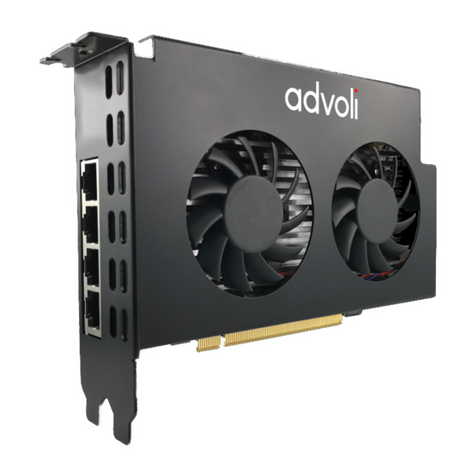
DFI LAX100 User manual

LAX100
Graphics Card
User’s Manual
A14510051

Copyright
This publication contains information that is protected by copyright. No part of it
may be reproduced in any form or by any means or used to make any transfor-
mation/adaptation without the prior written permission from the copyright hold-
ers.
This publication is provided for informational purposes only. The manufacturer
makes no representations or warranties with respect to the contents or use
of this manual and specifically disclaims any express or implied warranties of
merchantability or fitness for any particular purpose. The user will assume the
entire risk of the use or the results of the use of this document. Further, the
manufacturer reserves the right to revise this publication and make changes to
its contents at any time, without obligation to notify any person or entity of such
revisions or changes.
© 2010. All Rights Reserved.
Trademarks
All trademarks and registered trademarks of products appearing in this manual
are the properties of their respective holders.

FCC and DOC Statement on Class B
This equipment has been tested and found to comply with the limits for a Class B
digital device, pursuant to Part 15 of the FCC rules. These limits are designed to
provide reasonable protection against harmful interference when the equipment
is operated in a residential installation. This equipment generates, uses and can
radiate radio frequency energy and, if not installed and used in accordance with
the instruction manual, may cause harmful interference to radio communications.
However, there is no guarantee that interference will not occur in a particular
installation. If this equipment does cause harmful interference to radio or televi-
sion reception, which can be determined by turning the equipment off and on,
the user is encouraged to try to correct the interference by one or more of the
following measures:
• Reorientorrelocatethereceivingantenna.
• Increasetheseparationbetweentheequipmentandthereceiver.
• Connecttheequipmentintoanoutletonacircuitdifferentfromthattowhich
the receiver is connected.
• ConsultthedealeroranexperiencedradioTVtechnicianforhelp.
Notice:
1. The changes or modifications not expressly approved by the party responsible
for compliance could void the user’s authority to operate the equipment.
2. Shielded interface cables must be used in order to comply with the emission
limits.

1
4
Introduction
Table of Contents
Copyright........................................................................................... 2
Trademarks........................................................................................ 2
FCC and DOC Statement on Class B.............................................. 3
Warranty ........................................................................................... 5
Static Electricity Precautions............................................................. 6
Safety Measures ................................................................................. 6
About the Package ............................................................................ 7
Chapter 1 - Introduction .................................................................. 8
Specifications.................................................................................. 8
Chapter 2 - Hardware Installation.................................................. 10
Board Layout................................................................................ 10
Mechanical Dimensions................................................................... 12
Block Diagram............................................................................... 14
Handling the Graphics Card .......................................................... 15
Tips in Handling the Graphics Card................................................ 15
Installing the Graphics Card........................................................... 15
Jumper Settings............................................................................. 17
Connecting Display Devices........................................................... 19
Connecting an Analog Monitor to the VGA Port ............................ 20
Connecting a Digital LCD Monitor to the DVI-D Port ..................... 21
Connecting EXT-LAX100 to LAX100 .................................................. 22
Connector Pin Definition ................................................................. 23
Chapter 3 - Supported Software .................................................... 28
AXELL Graphics Drivers..................................................................................29
Adobe Acrobat Reader 9.3 ..............................................................................42

1
5
Introduction
Warranty
1. Warranty does not cover damages or failures that arised from misuse of the
product, inability to use the product, unauthorized replacement or alteration
of components and product specifications.
2. The warranty is void if the product has been subjected to physical abuse,
improper installation, modification, accidents or unauthorized repair of the
product.
3. Unless otherwise instructed in this user’s manual, the user may not, under
any circumstances, attempt to perform service, adjustments or repairs on the
product, whether in or out of warranty. It must be returned to the purchase
point, factory or authorized service agency for all such work.
4. We will not be liable for any indirect, special, incidental or consequencial
damages to the product that has been modified or altered.

1
6
Introduction
Static Electricity Precautions
It is quite easy to inadvertently damage your PC, graphics card, components
or devices even before installing them in your system unit. Static electrical dis-
charge can damage computer components without causing any signs of physical
damage. You must take extra care in handling them to ensure against electro-
static build-up.
1. To prevent electrostatic build-up, leave the graphics card in its anti-static bag
until you are ready to install it.
2. Wear an antistatic wrist strap.
3. Do all preparation work on a static-free surface.
4. Hold the device only by its edges. Be careful not to touch any of the compo-
nents, contacts or connections.
5. Avoid touching the pins or contacts on all modules and connectors. Hold
modules or connectors by their ends.
Important:
Electrostatic discharge (ESD) can damage your processor, disk drive and
other components. Perform the upgrade instruction procedures described
at an ESD workstation only. If such a station is not available, you can
provide some ESD protection by wearing an antistatic wrist strap and
attaching it to a metal part of the system chassis. If a wrist strap is
unavailable, establish and maintain contact with the system chassis
throughout any procedures requiring ESD protection.
Safety Measures
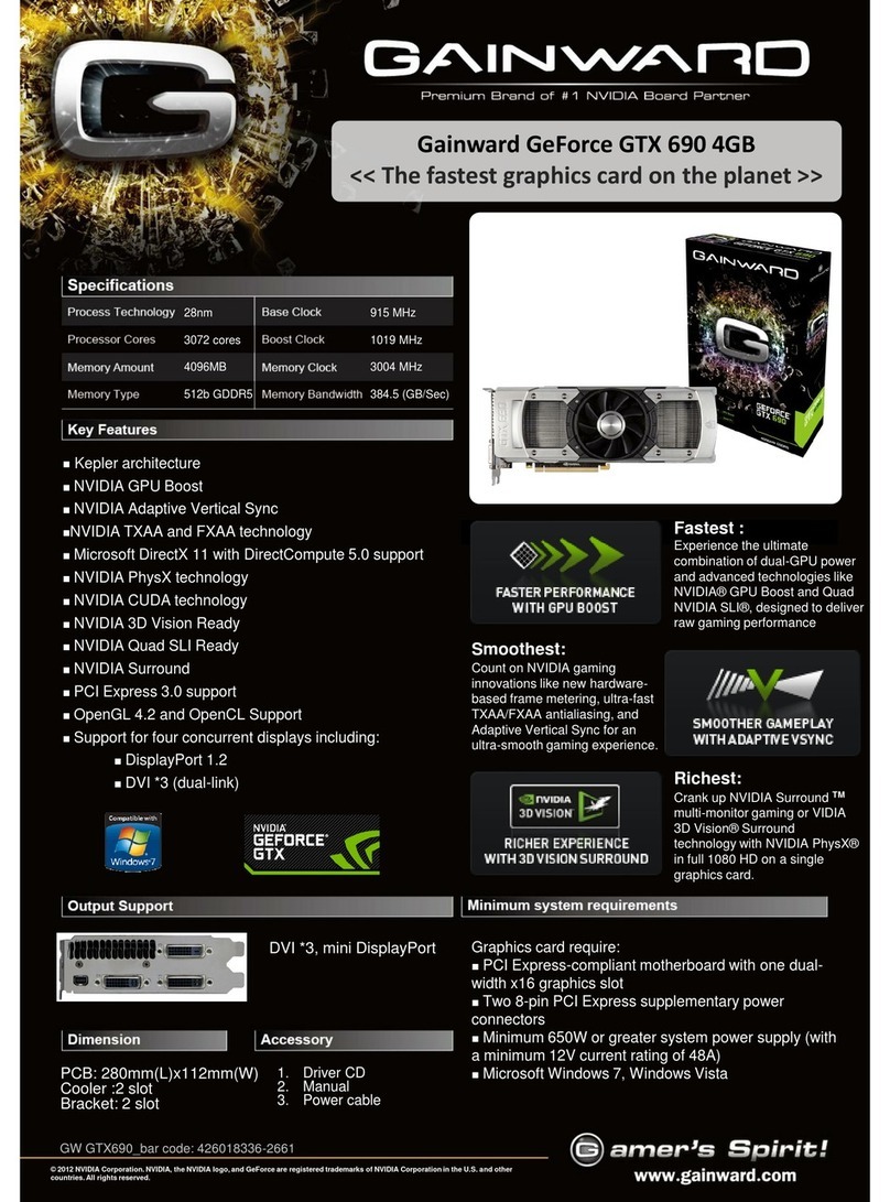
To avoid damage to the system:
• UsethecorrectACinputvoltagerange.
To reduce the risk of electric shock:
• Unplug the power cord before removing the system chassis cover for instal-
lation or servicing. After installation or servicing, cover the system chassis
before plugging the power cord.
Battery:
• Dangerofexplosionifbatteryincorrectlyreplaced.
• Replace only with the same or equivalent type recommend by the manufac-
turer.
• Disposeofusedbatteriesaccordingtolocalordinance.
1
7
Introduction
About the Package
The graphics card package contains the following items. If any of these items are
missing or damaged, please contact your dealer or sales representative for as-
sistance.
One graphics card
One CD
One QR (Quick Reference)
The graphics card and accessories in the package may not come similar to the
information listed above. This may differ in accordance to the sales region or
models in which it was sold. For more information about the standard package in
your region, please contact your dealer or sales representative.

1
8
Introduction
Chipset
Memory
PCI Express
Interface
2D Draw Engine
Draw Functions
Draw Capability
Display
Resolutions
Display Features
Video Output
Interface
Chapter 1 - Introduction
•AXELLAG10graphicschip
•Integrated512MbitVideoRAM(VRAM)onthegraphicschip
•PCIExpressx1interface
•CompliantwithPCIExpress1.1
•Lowpowerhardwareacceleration2Dengine
•BLTfunctions
•Primitivedrawingfunctions(point,line,triangle,rectangle)
•Triangletexturemapping
•Rectangleandtrianglegradationdrawing
•Pixelblending(alphablending,rasteroperation)
•Stenciloperation
•Supports16,777,216colors
•Maximum1920 x1200 dots,60Hz (whena singlescreen is
displayed
-A screen of this resolution can be displayed together
with a screen of 640 x 480 dots or smaller (total of two
screens)
•Maximum1280 x1024 dots,60Hz(when threescreens are
displayed)
•Maximum 1024 x 768 dots, 60Hz (when four screens are
displayed)
•Overlay(bilinearscaling,fourindependentdisplays)
•Hardware cursor (8 bit gradation stencil operation, four in-
dependentdisplays)
•1DB-15analogVGAport
•124-pindigitalDVI-Dport
•180-pinconnectorforoptionalEXT-LAX100daughterboard
-SiI164HDMItransmitter
-SiI7170DVItransmitter
-2HDMIports
-124-pindigitalDVI-Dport
-PCBdimensions:100mm(3.94”)x90mm(3.55”)
Note:
The board supports either the EXT-LAX100 daughterboard or
theLVDSoutputs.LVDSisnotsupportedonceyouhavecon-
nectedthedaughterboard.
Specifications

1
9
Introduction
Temperature
Humidity
PCBDimensions
•0oCto60oC
•10%to90%
•120mm(4.7”)x69mm(2.7”)

10
2Hardware Installation
Board Layout
Chapter 2 - Hardware Installation
40
39
2
12
1
40
39
2
1
15
VGA
LVDS Port 1 LVDS Port 2
1
Dual Link LVDS
Port 1 power
select (JP1)
1
1Single Link LVDS
Port 2/3 power
select (JP2, JP3)
Silicon
Image
SiI7170
JP2
JP3
AXELL
AG10
DVI-D
Daughterboard connector
2
1
80
79
LVDS Port 3
LAX100 Graphics Card
Note:
The LVDS ports and the Daughterboard connector are optional.

11
2
Hardware Installation
VGA
DVI-D
DVI-D
LAX100
Graphics Card
TMDS (HDMI)
EXT-LAX100
Daughterboard
TMDS (HDMI)

12
2Hardware Installation
Mechanical Dimensions
100
80.52
59.67
20.3
13
0
0
15
48.29
90 90
0
100
8.25
0
64.4
20.3
13
0
0
15
33.35
41.35
45
57.15
65.3
120.03
4.5
8.25
64.4
120.03
48.29
0
LAX100
EXT-LAX100
LAX100
Graphics Card

13
2
Hardware Installation
100
80.52
59.67
20.3
13
0
0
15
48.29
90 90
0
100
8.25
0
64.4
20.3
13
0
0
15
33.35
41.35
45
57.15
65.3
120.03
4.5
8.25
64.4
120.03
48.29
0
LAX100
EXT-LAX100
EXT-LAX100
Daughterboard

14
2Hardware Installation
Block Diagram
AG10
PCI-Express
Golden Finger
Board
to
Board
Connector
Transmitter
Analog RGB
LVDS Dual
Reset
OSC
SPI ROM
VGA
DVI-D
TMDS
LVDS Dual
LVDS Single
LVDS Single
Board
to
Board
Connector
Transmitter
LVDS Dual
DVI-D
TMDS
Transmitter
LVDS Single
HDMI
Transmitter
LVDS Single
HDMI
TMDS
TMDS
Block Diagram
LAX100
EXT-LAX100
LAX100
Graphics Card
AG10
PCI-Express
Golden Finger
Board
to
Board
Connector
Transmitter
Analog RGB
LVDS Dual
Reset
OSC
SPI ROM
VGA
DVI-D
TMDS
LVDS Dual
LVDS Single
LVDS Single
Board
to
Board
Connector
Transmitter
LVDS Dual
DVI-D
TMDS
Transmitter
LVDS Single
HDMI
Transmitter
LVDS Single
HDMI
TMDS
TMDS
Block Diagram
LAX100
EXT-LAX100
EXT-LAX100
Daughterboard

15
2
Hardware Installation
Handling the Graphics Card
It is quite easy to inadvertently damage your graphics card even before installing
it in your system unit. Electrostatic discharge can damage computer components
without causing any signs of physical damage. You must take extra care in han-
dling the graphics card to ensure that no static build-up is present.
Tips in Handling the Graphics Card
1. To prevent electrostatic build-up, leave the graphics card in its anti-static bag
until you are ready to install it.
2. Do all preparation work on a static-free surface with graphics card compo-
nents facing up.
3. Hold the graphics card by its edges only. Be careful not to touch any of the
components, contacts or connections, especially gold contacts, on the board.
Installing the Graphics Card
For most computer systems, you will only need a medium size Phillips screw-
driver to remove the cover and a small at-blade screwdriver to secure the moni-
tor cable.
Important:
Electrostatic discharge (ESD) can damage the graphics card, system
board, processor, disk drives, add-in boards, and other components.
Perform the upgrade instruction procedures described at an ESD work-
station only. If such a station is not available, you can provide some
ESD protection by wearing an antistatic wrist strap and attaching it to a
metal part of the system chassis. If a wrist strap is unavailable, establish
and maintain contact with the system chassis throughout any procedures
requiring ESD protection.

16
2Hardware Installation
Step 1: Power-Off the Computer
Make sure the computer and all other peripheral devices connected to it has been
powered down. Disconnect all power cords and cables.
Important:
Hazardous voltages are present and exposed when operating the com-
puter with the cover removed. To prevent equipment damage and per-
sonal injury, never apply power to the computer when the cover is off.
Important:
If your computer comes with an onboard graphics capability, you may
need to disable the onboard function from the system board’s BIOS.
However, some manufacturers does not allow the built-in graphics to
be disabled or set as secondary display. Refer to the documentation or
manual included in the computer’s package for more information.
Step 2: Remove the Computer’s Cover
Refer to your computer system manual for specic instructions on removing your
computer’s system unit cover. In general, you will need to remove several screws
on the back or side of the system unit and then slide the cover off.
Step 3: Remove the Slot Cover
Remove the slot-cover screw and slot cover adjacent to the PCI Express slot. Put
them in a safe place for later use.
Step 4: Unpack the Graphics Card
Remove the graphics card from the shipping carton and its protective packing.
Please do not throw away the packing material or the shipping box. You may use
these again to prevent damage should you need to ship the graphics card for
repairs.
Step 5: Insert the Graphics Card
Align the graphics card above the PCI Express slot then press it down rmly until
it is completely seated in the slot. Make sure the graphics card is straight and
level compared to the computer’s system board by viewing it from the side.
Step 6: Replace the Slot-Cover Screw
Secure the graphics card with the slot-cover screw you removed in step 3.
Step 7: Replace the Computer’s Cover
After you have nished installing the graphics card, put the computer’s cover
back on the system unit. Refer to the computer’s system manual for instructions
if necessary.
Step 8: Connect a Monitor or LCD Panel
Refer to the “Connecting Display Devices” section for details.

17
2
Hardware Installation
Jumper Settings
Dual Link LVDS Port 1 Power Select (optional)
JP1 is used to select the power supplied to LVDS Port 1.
LVDS Port 1 supports 24-bit dual channel LVDS display.
2-3 On:
5V
1-2 On: 3.3V
(default)
JP1
1
3
2
1
3
2
LVDS Port 1

18
2Hardware Installation
Dual Link LVDS Port 2 / Port 3 Power Select (optional)
JP2 and JP3 are used to select the power supplied to LVDS Port 2 and LVDS Port
3.
LVDS Port 2 and Port 3 support 24-bit single channel LVDS display.
2-3 On:
5V
1-2 On: 3.3V
(default)
JP2
1
3
2
1
3
2
LVDS Port 2
LVDS Port 3
JP3

19
2
Hardware Installation
Connecting Display Devices
The graphics card allows multiple displays by means of the VGA port, DVI-D port
and the LVDS connectors. Devices connected to these interfaces can be displayed
simultaneously.
VGA
DVI-D
LVDS Port 1 LVDS Port 2/3

20
2Hardware Installation
Connecting an Analog Monitor to the VGA Port
Connect the analog monitor’s cable connector to the VGA port. After you plug the
cable connector into the VGA port, gently tighten the cable screws to hold the
connector in place.
Analog Monitor
Table of contents
Other DFI Video Card manuals
Popular Video Card manuals by other brands

Diamond Multimedia
Diamond Multimedia ATI Radeon 2600PRO512PE Specification sheet

phase 5
phase 5 BLIZZARD 1230-III Turbo Board user manual

Asus
Asus V8170 PRO/T/64M Quick start manual

MSI
MSI RX300HM-TD128E Quick installation guide

Gigabyte
Gigabyte GV-RX165T256D-RH manual

FOR-A
FOR-A MFR-9SDI12G installation guide