DG Flugzeugbau LS4 User manual
Maintenance Manual LS4
Issued: May 2011
Copyright DG Flugzeugbau GmbH - any copy or publishing prohibited
Manual valid with the up-to-date cover page only
0-1
Recommendations to order spare parts
Please try to determine the exact designations of the spare parts for your order
using the maintenance manual. This is to guarantee a fast and correct delivery of
the parts.
The designations are to find in the sections system description, instructions for
assembly and servicing work and especially in the diagrams of the maintenance
manual.
Yours sincerely
DG FLUGZEUGBAU GMBH
Dipl.- Ing. W. Dirks

Maintenance Manual LS4
Issued: February 2019 TN4049
Copyright DG Flugzeugbau GmbH - any copy or publishing prohibited
Manual valid with the up-to-date cover page only
0-2
0General
0.1 Manual amendments
No.
Page
Description
Date
0.1
all
Combination of the initial
Maintenance Manuals of
the Variants LS4, LS4-a
and
LS4-b, new standardized
format
May 2011
0.2
0-11, 1-1 ÷ 1-7, 1-10 ÷ 1-15,
2-1 ÷ 2-6, 2-15, 2-17, 2-20,
2-21, 2-23, 3-1 ÷ 3-4, 3-6, 3-
7, 4-1, 4-5 ÷ 4-7, 4-9, 4-16,
4-18 ÷ 4-20, 5-1 ÷ 5-3, 6-1,
7-6, 8-1, 9--1 ÷ 9-4,
10-1 ÷ 10-3, 11-1 ÷ 11-10
12-1, 12-2, 13-1,
14-3 ÷ 14-7
Miscellaneous changes to
the contents of the latest
amendments of the initial
maintenance manuals
May 2011
1
0-2, 0-4 - 0-6, 1-1, 2-2, 2-3,
2-5, 2-17, 4-6, 7-3, 7-5
neo-Winglets TN4049
February
2019

Maintenance Manual LS4
Issued: May 2011
Copyright DG Flugzeugbau GmbH - any copy or publishing prohibited
Manual valid with the up-to-date cover page only
0-3
Page intentionally left blank

Maintenance Manual LS4
Issued: February 2019 TN4049
Copyright DG Flugzeugbau GmbH - any copy or publishing prohibited
Manual valid with the up-to-date cover page only
0-4
0.2 List of effective pages
Section
page
issued
replaced
replaced
replaced
0
0-0
May 2011
0-1
See list of amendments
0-2
"
0-3
"
0-4
"
0-5
"
0-6
May 2011
0-7
"
0-8
"
0-9
"
0-10
"
0-11
"
1
1-1
May 2011
Febr. 2019
1-2
"
1-3
"
1-4
"
1-5
"
1-6
"
1-7
"
1-8
"
1-9
"
1-10
"
1-11
"
1-12
"
1-13
"
1-14
"
1-15
"
2
2-1
May 2011
2-2
“
Febr. 2019
2-3
“
Febr. 2019
2-4
“
2-5
“
Febr. 2019
2-6
“
2-7
“
2-8
“
2-9
“
2-10
“
2-11
"
2-12
"

Maintenance Manual LS4
Issued: February 2019 TN4049
Copyright DG Flugzeugbau GmbH - any copy or publishing prohibited
Manual valid with the up-to-date cover page only
0-5
0.2 List of effective pages (continued)
Section
page
issued
replaced
replaced
replaced
2 cont.
2-13
May 2011
2-14
“
2-15
“
2-16
“
2-17
“
Febr. 2019
2-18
“
2-19
“
2-20
“
2-21
“
2-22
2-23
2-24
3
3-1
May 2011
3-2
"
3-3
"
3-4
"
3-5
"
3-6
"
3-7
"
4
4-1
May 2011
4-2
"
4-3
"
4-4
"
4-5
"
4-6
"
Febr. 2019
4-7
"
4-8
"
4-9
"
4-10
"
4-11
"
4-12
"
4-13
"
4-14
"
4-15
"
4-16
"
4-17
"
4-18
"
4-19
"
4-20
"
5
5-1
May 2011
5-2
"
5-3
"
5-4
"

Maintenance Manual LS4
Issued: February 2019 TN4049
Copyright DG Flugzeugbau GmbH - any copy or publishing prohibited
Manual valid with the up-to-date cover page only
0-6
0.2 List of effective pages (continued)
Section
page
issued
replaced
replaced
replaced
5 cont.
5-5
May 2011
5-6
“
6
6-1
May 2011
7
7-1
May 2011
7-2
“
7-3
“
Febr. 2019
7-4
“
7-5
“
Febr. 2019
7-6
“
8
8-1
May 2011
8-2
"
8-3
"
9
9-1
May 2011
9-2
"
9-3
"
9-4
"
10
10-1
May 2011
10-2
"
10-3
"
11
11-1
May 2011
11-2
"
11-3
"
11-4
"
11-5
"
11-6
"
11-7
"
11-8
"
11-9
"
11-10
"
12
12-1
May 2011
12-2
"
13
13-1
May 2011
14
14-1
May 2011
14-2
"
14-3
"
14-4
"
14-5
"
14-6
"
14-7
"

Maintenance Manual LS4
Issued: May 2011
Copyright DG Flugzeugbau GmbH - any copy or publishing prohibited
Manual valid with the up-to-date cover page only
0-7
0.3 Table of Contents
Section Content……………………………………………………………..page
0General.....................................................................................................0-2
0.1 Manual amendments................................................................................0-2
0.2 List of effective pages..............................................................................0-4
0.3 Table of Contents.....................................................................................0-7
0.4 Airworthiness Limitations .....................................................................0-11
0.4.1 Repairs..............................................................................................0-11
0.4.2 Life time of the airframe...................................................................0-11
0.4.3 Life time of equipment and components..........................................0-11
0.4.4 Service time, maintenance documents of equipment and components
..........................................................................................................0-11
1Description of systems.............................................................................1-1
1.1 Wings.......................................................................................................1-1
1.2 Aileron control.........................................................................................1-2
1.2.1 Aileron control LS4 and LS4-a ..........................................................1-2
1.2.2 Aileron control LS4-b.........................................................................1-2
1.3 Elevator Controls and Trim-System:.......................................................1-3
1.3.1 Elevator Controls................................................................................1-3
1.3.2 Trim Controls......................................................................................1-3
1.4 Rudder control system .............................................................................1-4
1.5 Wheel brake .............................................................................................1-4
1.6 Air brake controls ....................................................................................1-5
1.6.1 Air brake controls LS4 and LS4-a......................................................1-5
1.6.2 Air brake controls LS4-b....................................................................1-5
1.7 Water ballast system and sketches for wing control systems..................1-6
1.7.1 Water Ballast System LS4 and LS4-a................................................1-6
1.7.2 Water Ballast System LS4-b ..............................................................1-7
1.7.3 Wing control systems LS4 and LS4-a................................................1-8
1.7.4 Wing control systems LS4-b ..............................................................1-8
1.8 Cockpit.....................................................................................................1-9
1.8.1 Cockpit LS4 and LS4-a ......................................................................1-9
1.8.2 Cockpit LS4-b.....................................................................................1-9
1.9 Canopy.....................................................................................................1-9
1.9.1 Canopy LS4 and LS4-a.......................................................................1-9
1.9.2 Canopy LS4-b.....................................................................................1-9
1.9.3 Canopy LS4-b standard, LS4 and LS4-a with TN4032 executed....1-10
1.10 Instrument panel.....................................................................................1-10
1.10.1 LS4 and LS4-a instrument panel......................................................1-10
1.10.2 LS4-b instrument panel ....................................................................1-10
1.11 Baggage compartment ...........................................................................1-10

Maintenance Manual LS4
Issued: May 2011
Copyright DG Flugzeugbau GmbH - any copy or publishing prohibited
Manual valid with the up-to-date cover page only
0-8
Section Content……………………………………………………………..page
1.12 Oxygen system.......................................................................................1-10
1.12.1 LS4 and LS4-a Oxygen system........................................................1-10
1.12.2 LS4-b Oxygen system ......................................................................1-10
1.13 Landing gear ..........................................................................................1-11
1.14 Wheel Brake...........................................................................................1-12
1.15 Hint for working at the control systems ................................................1-13
1.16 Pressure ports.........................................................................................1-14
1.16.1 Pressure ports LS4, LS4-a:...............................................................1-14
1.16.2 Pressure ports LS4-b:........................................................................1-14
1.17 Drain orifices .........................................................................................1-15
1.18 Colour coding of instrument lines .........................................................1-15
2Mass and balance.....................................................................................2-1
2.1 Weighing procedure.................................................................................2-1
2.2 Calculation of loading limits, example....................................................2-3
2.2.1 Calculation of loading limits ..............................................................2-3
2.2.2 Examples for calculation of loading limits.........................................2-5
2.3 Empty mass C.G. range ...........................................................................2-6
2.4 Max. mass of non-lifting parts...............................................................2-17
2.4.1 Calculation of max. mass of non-lifting parts (standard water bags) .....
...................................................................................................... 2-17
2.4.2 Calculation of max. mass of non-lifting parts according to TN 4046
with water bags V112 according to TN 4047...................................2-21
3Inspections ...............................................................................................3-1
3.1 Regular inspections..................................................................................3-1
3.1.1 Daily Inspections................................................................................3-1
3.1.2 Annual Inspections .............................................................................3-1
3.2 Extraordinary inspections after heavy landings.......................................3-5
3.3 Inspection procedure for increase of service time...................................3-6
3.4 Lubrication schedule................................................................................3-7
4Working instructions................................................................................4-1
4.1 Removal and installation of control surfaces...........................................4-1
4.1.1 Ailerons...............................................................................................4-1
4.1.2 Elevator...............................................................................................4-3
4.1.3 Rudder.................................................................................................4-4
4.2 Installation of control surface gap sealings and turbulators ....................4-5
4.2.1 Installation of internal seals................................................................4-5
4.2.2 Gap seals aileron.................................................................................4-6
4.2.3 Gap sealings elevator..........................................................................4-7
4.2.4 Gap seals rudder .................................................................................4-7
4.2.5 Turbulator on lower wing surface ......................................................4-8

Maintenance Manual LS4
Issued: May 2011
Copyright DG Flugzeugbau GmbH - any copy or publishing prohibited
Manual valid with the up-to-date cover page only
0-9
Section Content……………………………………………………………..page
4.3 Removal and installation of seat shell .....................................................4-9
4.3.1 Removal and installation of seat shell LS4 and LS4-a.......................4-9
4.3.2 Removal and installation of seat shell LS4-b.....................................4-9
4.4 Adjustment of water ballast valves........................................................4-11
4.5 Removal and installation of the wing water ballast bags:.....................4-12
4.5.1 Removal of the wing water ballast bags...........................................4-12
4.5.2 Assembly of the wing water ballast bags.........................................4-13
4.5.3 Installation of the wing water ballast bags.......................................4-14
4.6 Removal and installation of the tail fin water ballast tank (Option) .....4-15
4.6.1 Tail fin water ballast tank removal...................................................4-15
4.6.2 Tail fin water ballast tank installation:.............................................4-15
4.7 Removal and installation of the C.G. Hook...........................................4-16
4.7.1 Removal of the C.G. Hook...............................................................4-16
4.7.2 Installation of the C.G. hook ............................................................4-16
4.8 Removal and installation of the nose hook (Option).............................4-18
4.8.1 Removal of the nose hook................................................................4-18
4.8.2 Installation of nose hook...................................................................4-18
4.9 Canopy emergency release ....................................................................4-19
5Control surfaces .......................................................................................5-1
5.1 Control surface deflection limits..............................................................5-1
5.2 Control surface weight and mass balance................................................5-2
5.3 Control surfaces free play........................................................................5-3
5.4 Control surfaces friction ..........................................................................5-3
5.5 Limit values for control surface deflections in mm/in. ,only LS4-b.......5-4
6Special tools:............................................................................................6-1
7Placards and markings .............................................................................7-1
7.1 Placards and markings LS4......................................................................7-1
7.2 Placards and markings LS4-a .................................................................7-3
7.3 Placards and markings LS4-b.................................................................7-5
8Permanent installation of fixed ballast and equipment............................8-1
8.1 Fixed ballast under instrument panel.......................................................8-1
8.2 Fixed Ballast at rear fuselage end............................................................8-2
8.3 Permanent installation of equipment in baggage compartment...............8-3

Maintenance Manual LS4
Issued: May 2011
Copyright DG Flugzeugbau GmbH - any copy or publishing prohibited
Manual valid with the up-to-date cover page only
0-10
Section Content……………………………………………………………..page
9Instruments- and Equipment List (Master Equipment List)....................9-1
9.1 Airspeed Indicator....................................................................................9-1
9.2 Altimeter ..................................................................................................9-2
9.3 Seat Belt Harness (with multiple point buckles) .....................................9-2
9.4 Compass...................................................................................................9-2
9.5 UHF –Transmitter and Receiver.............................................................9-3
9.6 Variometer ...............................................................................................9-3
9.7 Turn and Bank Indicator..........................................................................9-3
9.8 Thermometer............................................................................................9-4
9.9 Electrical Supply......................................................................................9-4
9.10 Equipment, not being part of minimum equipment:................................9-4
10 Materials for repair ................................................................................10-1
11 Repairs ...................................................................................................11-1
11.1 Preface....................................................................................................11-1
11.2 Repairs of composite structures, General..............................................11-2
11.3 Tools and facilities required ..................................................................11-3
11.4 Instructions for FRP repairs...................................................................11-4
11.4.1 General..............................................................................................11-4
11.4.2 Repairs of a FRP shell......................................................................11-4
11.4.3 Repairing the outer skin of a foam sandwich panel ........................11-4
11.4.4 Repair of outer and inner skin of a sandwich panel.........................11-5
11.4.5 Repairing small dents in a sandwich panel skin (no cracks in the
gelcoat) .............................................................................................11-5
11.4.6 Outer skin finish ...............................................................................11-6
11.4.7 Repairing control surfaces................................................................11-6
11.5 Types of materials and overlap dimensions...........................................11-7
11.6 Control cables and connections .............................................................11-9
11.7 Longitudinal motion pushrod bearings................................................11-10
12 Recommendations for maintenance and care of gelcoat surfaces.........12-1
12.1 General...................................................................................................12-1
12.2 "Schwabbel" procedure:.........................................................................12-2
13 Transport of sailplane ............................................................................13-1
13.1 Support areas for road-transport............................................................13-1
13.2 Support areas when lifting the entire plane ...........................................13-1
13.3 Ground Towing......................................................................................13-1
14 Appendix................................................................................................14-1
14.1 Annual inspection checklist...................................................................14-1
14.2 Instruction for maintenance of L’Hotellier ball and swivel joints ........14-4

Maintenance Manual LS4
Issued: May 2011
Copyright DG Flugzeugbau GmbH - any copy or publishing prohibited
Manual valid with the up-to-date cover page only
0-11
0.4 Airworthiness Limitations
0.4.1 Repairs
Repair or replace damaged parts prior to next flight. Follow the instructions
of section 11 of this manual for repairs of the airframe. Major repairs must
be accomplished at an approved repair station or by an approved mechanic
rated for composite aircraft structure work in accordance with DG repair
methods.
Use only genuine spare parts.
For all aircraft under EASA regulations the following applies: According to
part 21, subpart M to accomplish major repairs an approved repair
instruction is required, see also TN DG-G-01 “Approved repair methods
according to EU Commission Regulation 1702/2003 part 21, subpart M”
0.4.2 Life time of the airframe
The maximum allowable operating time for the Variants LS4, LS4-a and
LS4-b is 12000 flight hours. Therefore inspections according to section 3.3
of this manual have to be executed at 3000 h, 6000 h, 9000 h and every
1000 hours following thereafter.
0.4.3 Life time of equipment and components
a) The fabric straps of the safety harness have to be exchanged according to
the instructions of the respective manufacturer. If no limitations are given,
exchange after 12 years.
b) Other components:
All other components like tow hooks, wheels, gas struts, control system
parts, bolts, pins etc. have no life time limitation, but should be replaced
when worn, damaged or disqualified by excessive corrosion.
0.4.4 Service time, maintenance documents of equipment and components
Follow the instructions of the respective manufacturer:
a) Operating Manual for Safety Tow Releases
Series: Europa G 72 or Europa G 73 or Europa G 88 Safety Tow Release
latest approved version
And if installed:
Operating Manual for Tow Releases Series: E72 or E75 or E 85 Nose Tow
Release latest approved version
b) Safety harness: instructions of the manufacturer.
c) Minimum instrumentation: instructions of the manufacturer.

Maintenance Manual LS4
Issued: February 2019 TN4049
Copyright DG Flugzeugbau GmbH - any copy or publishing prohibited
Manual valid with the up-to-date cover page only
1-1
1Description of systems
1.1 Wings
GFRP wing, wing span 15 m.
With TN4045 performed: removable 15 m wingtips which may be
replaced by wingtips with Winglets (so called Wolfsohren).
Caution: For operation with Winglets (TN4045) the max. payload must be
reduced by 10 kg /22 lbs..
With TN4049 performed: removable 15 m wingtips which may be
replaced by wingtips with neo-Winglets.
Caution: For operation with neo-Winglets (TN4049) the max. payload must not
be reduced as with TN4045.
The max. mass of the non-lifting parts is set to 250 kg / 517 lbs. for all LS4
variants (TN4046/4047 must be performed).
The determination of the max. mass of the non-lifting parts in relation to the
empty mass C.G. according to section 2.4 is not applicable.
The max. take-off and landing mass will remain 472 kg / 1041 lbs. for variant
LS4 and will be reduced to 505 kg / 1113 lbs. for variants LS4-a and LS4-b with
neo-Winglets installed.
Maintenance Manual LS4
Issued: May 2011
Copyright DG Flugzeugbau GmbH - any copy or publishing prohibited
Manual valid with the up-to-date cover page only
1-2
1.2 Aileron control
1.2.1 Aileron control LS4 and LS4-a
Activation via pushrods, with ball and swivel joints in fuselage and LS-
securing sleeves at wings side. Ailerons partly massbalanced.
1.2.2 Aileron control LS4-b
Activation via pushrods, with automatic hookup (system Hänle). Ailerons
partly massbalanced.
Note: The sketches for the control systems in the wings are to be found in
section 1.7.
LS4-b
LS4 und LS4-a

Maintenance Manual LS4
Issued: May 2011
Copyright DG Flugzeugbau GmbH - any copy or publishing prohibited
Manual valid with the up-to-date cover page only
1-3
1.3 Elevator Controls and Trim-System:
1.3.1 Elevator Controls
Elevator system activated via pushrods. Automatic coupling during
assembly of horizontal tail unit.
100% mass balance in vertical tail fin pushrod.
1.3.2 Trim Controls
Trim handle at left hand cockpit wall behind landing gear handle-
Maintenance Manual LS4
Issued: May 2011
Copyright DG Flugzeugbau GmbH - any copy or publishing prohibited
Manual valid with the up-to-date cover page only
1-4
1.4 Rudder control system
Rudder activated via steel cables guided in polyamide tubing,. 100% mass
balance at rudder.
1.5 Wheel brake
Feet operated, activated by bowden cable from rudder pedals.

Maintenance Manual LS4
Issued: May 2011
Copyright DG Flugzeugbau GmbH - any copy or publishing prohibited
Manual valid with the up-to-date cover page only
1-5
1.6 Air brake controls
1.6.1 Air brake controls LS4 and LS4-a
Activation via pushrods, with L’Hotellier connectors in fuselage and LS-
securing sleeves wingside.
Upper surface double storey airbrakes with spring loaded caps.
1.6.2 Air brake controls LS4-b
Activated via pushrods. Automatic connection of system during rigging
(Hänle system). Air brake locking in wings.
Upper surface double storey air brakes with spring loaded caps.
Friction damper in airbrake box to prevent oscillations during extension.
Note: The sketches for the control systems in the wings are to be found in
section 1.7.3 and 1.7.4.
LS4 und LS4-a LS4-b
Maintenance Manual LS4
Issued: May 2011
Copyright DG Flugzeugbau GmbH - any copy or publishing prohibited
Manual valid with the up-to-date cover page only
1-6
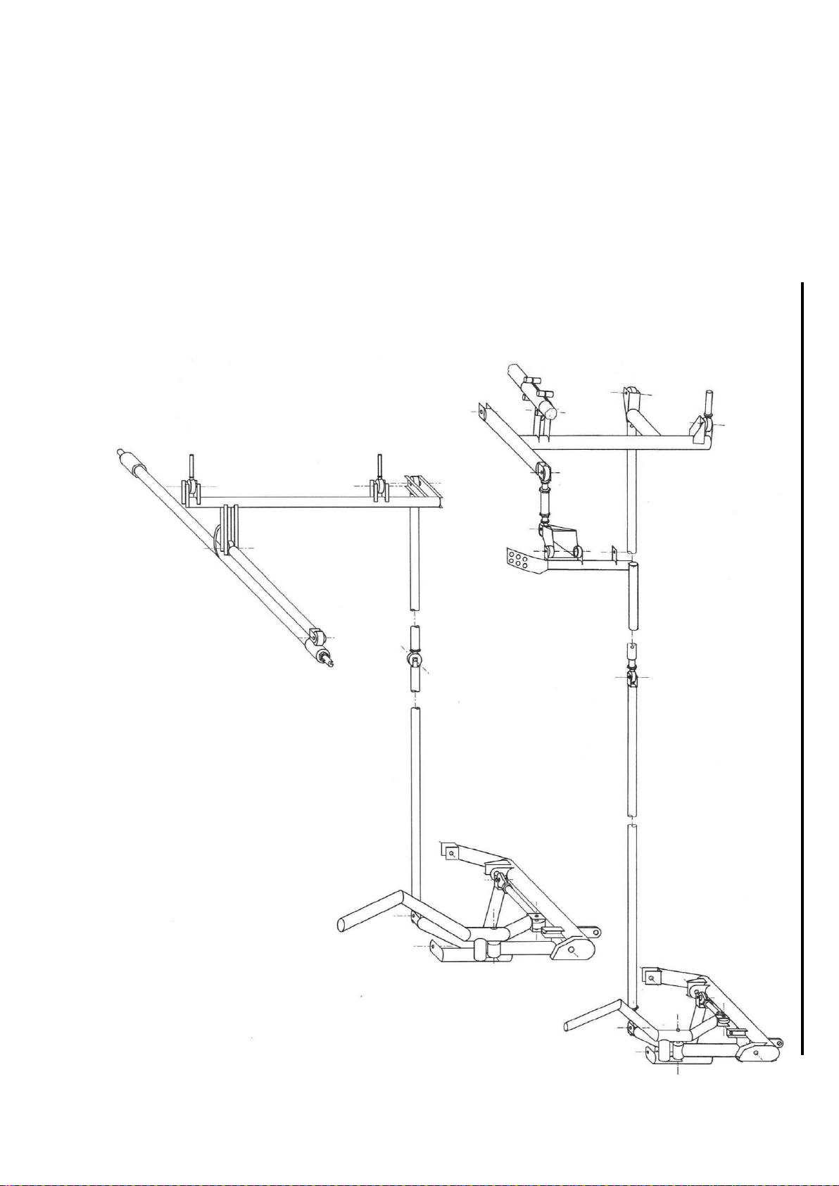
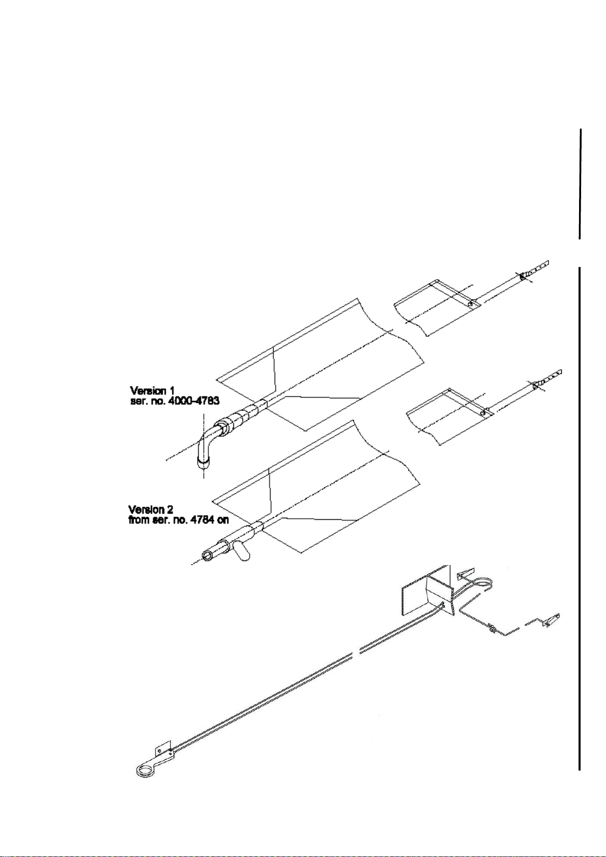
1.7 Water ballast system and sketches for wing control systems
1.7.1 Water Ballast System LS4 and LS4-a
LS4 and LS4-a : Waterbags 4F5-13 (approx. 70 Liter <18.5 US gallons>
per wing) or
LS4-a optionally: 3F5-25 (approx. 85 Liter <22.45 US gallons> per wing),
retrofit for LS4 see TN 4014.
The bags 3F5-25 consist of 2 bags per wing which are connected via a tube
running from the valve at the root through the inner bag to the outboard
bag. The valve is constructed as a double valve.
Loading and dumping port on lower side of wings. Automatic hook-up
during rigging. Drive of valves at root rib via push rods.
Water ballast system in wings
LS4 and LS4-a
Water Ballast System in fuselage
LS4 and LS4-a

Maintenance Manual LS4
Issued: May 2011
Copyright DG Flugzeugbau GmbH - any copy or publishing prohibited
Manual valid with the up-to-date cover page only
1-7
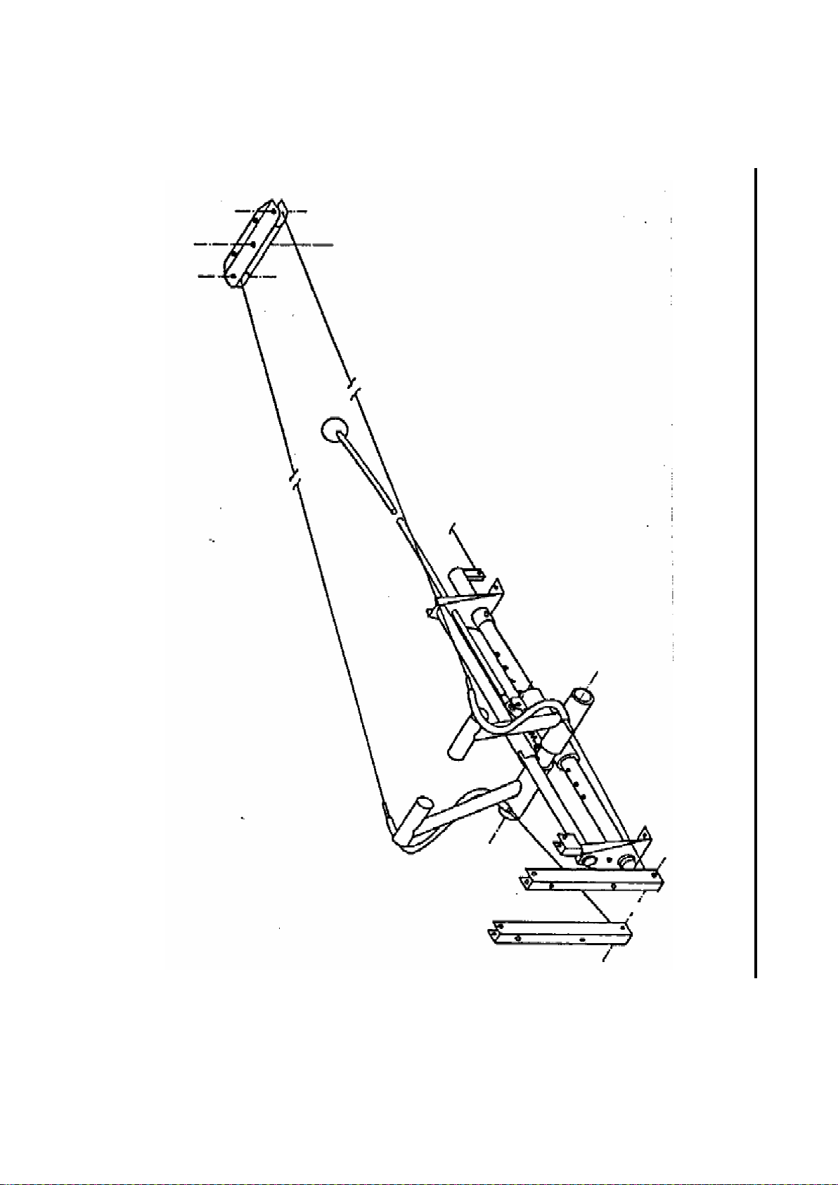
1.7.2 Water Ballast System LS4-b
Waterbag 4F5-35 (approx. 85 Liters <22.45 US gallons > per wing),
optionally 4F5-13 (approx. 70 Liter <18.5 US gallons> per wing) or
waterbag 4F5-81 (50 Liters <13.2 US gallons> per wing).
Valves / loading and dumping port on lower side of wings. Automatic
hook-up during rigging. Drive of valves at root rib via push rods.
If installed: In the vertical tail fin either battery receptacle or ballast tank
allowing to compensate C.G. shift due to wing water ballast or mass of
heavy pilots, maximum capacity 5 Liters <1.32 US gallons). When the tail
fin tank is combined with a battery receptacle, the maximum capacity is 3.5
Liters <0.92 US gal.>
Water ballast system in wings LS4-b
Water ballast System LS4-b in fuselage,
optional fin tank

Maintenance Manual LS4
Issued: May 2011
Copyright DG Flugzeugbau GmbH - any copy or publishing prohibited
Manual valid with the up-to-date cover page only
1-8
1.7.3 Wing control systems LS4 and LS4-a
1.7.4 Wing control systems LS4-b
Friction damper

Maintenance Manual LS4
Issued: May 2011
Copyright DG Flugzeugbau GmbH - any copy or publishing prohibited
Manual valid with the up-to-date cover page only
1-9
1.8 Cockpit
1.8.1 Cockpit LS4 and LS4-a
Double fiberglass shell.
Controls for airbrakes, landing gear on left cockpit side.
Control for longitudinal trim (acting as trim position indicator also) located
on left cockpit side behind landing gear handle, trim locking lever at
control stick.
Control for tow cable release (operating C.G. hook and optional nose
hook), for pedal adjustment, canopy emergency release and for ventilation
on instrument panel.
Handle for water ballast valve and for adjustment of the back rest
inclination on right hand side of cockpit.
Handles for canopy opening on both sides.
1.8.2 Cockpit LS4-b
Double fiberglass shell.
Controls for airbrakes, landing gear, tow cable release (operating C.G.
hook and optional nose hook) on left cockpit side.
Control for longitudinal trim (acting as trim position indicator also) located
on left cockpit side behind landing gear handle, trim locking lever at
control stick.
Handle for pedal adjustment left near centre of seat shell.
Handle for ventilation on instrument panel cover.
Handle for water ballast on right hand side of cockpit,
Handles for canopy opening on both sides.
When operating right canopy lever over full possible travel, the forward
canopy mount becomes disengaged (emergency canopy release).
Adjustment of the back rest inclination only on the ground via latching
device in the baggage compartment.
1.9 Canopy
One piece front hinged canopy. 2 threads at left and right hand sides of the
canopy frame for installation of cameras or other equipment are standard
equipment.
1.9.1 Canopy LS4 and LS4-a
Instrument panel cover fixed to canopy.
With TN4032 executed: A spring at the canopy hinge lifts the canopy in
case of canopy emergency release.
1.9.2 Canopy LS4-b
After operating the canopy emergency release the canopy will be lifted at
the front by the instrument panel, which is lifted by a gas strut.
This manual suits for next models
2
Table of contents


