DGSHAPE DE-3 User manual

• To ensure safe use with a full understanding of this machine's performance, please be sure to read through this
manual completely.
• Store this manual in a safe place where it can be referred to when needed.
• Reproduction, citation, or translation, in whole or in part, of this manual is prohibited without the express written
consent of DGSHAPE Corporation.
• The contents of this operation manual and the specications of this product are subject to change without notice.
• DGSHAPE Corporation assumes no responsibility for any damage that may occur through use of this product,
regardless of any failure to perform on the part of this product or of any errors in this document. Damage includes
but is not limited to damage caused by the specications or performance of the product, damage caused by non-
use of the product, and damage caused by deliverables obtained through use of this product. Such damage can be
either direct or indirect.

Contents
Contents..............................................................................................................................................................................................1
Chapter 1 Getting Started ................................................................................................4
About This Machine ........................................................................................................................................................................5
Features of This Machine..............................................................................................................................................5
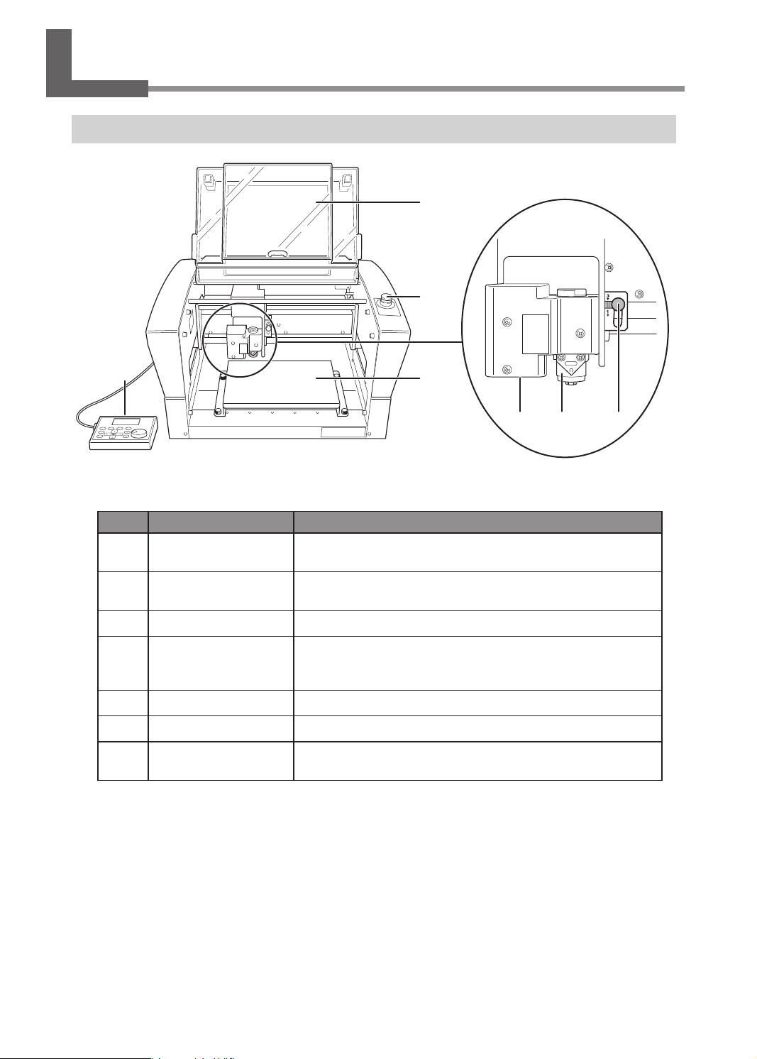
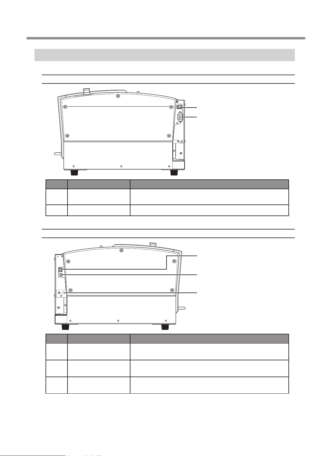
Part Names and Functions............................................................................................................................................................6
Front and Interior............................................................................................................................................................6
Side.......................................................................................................................................................................................7
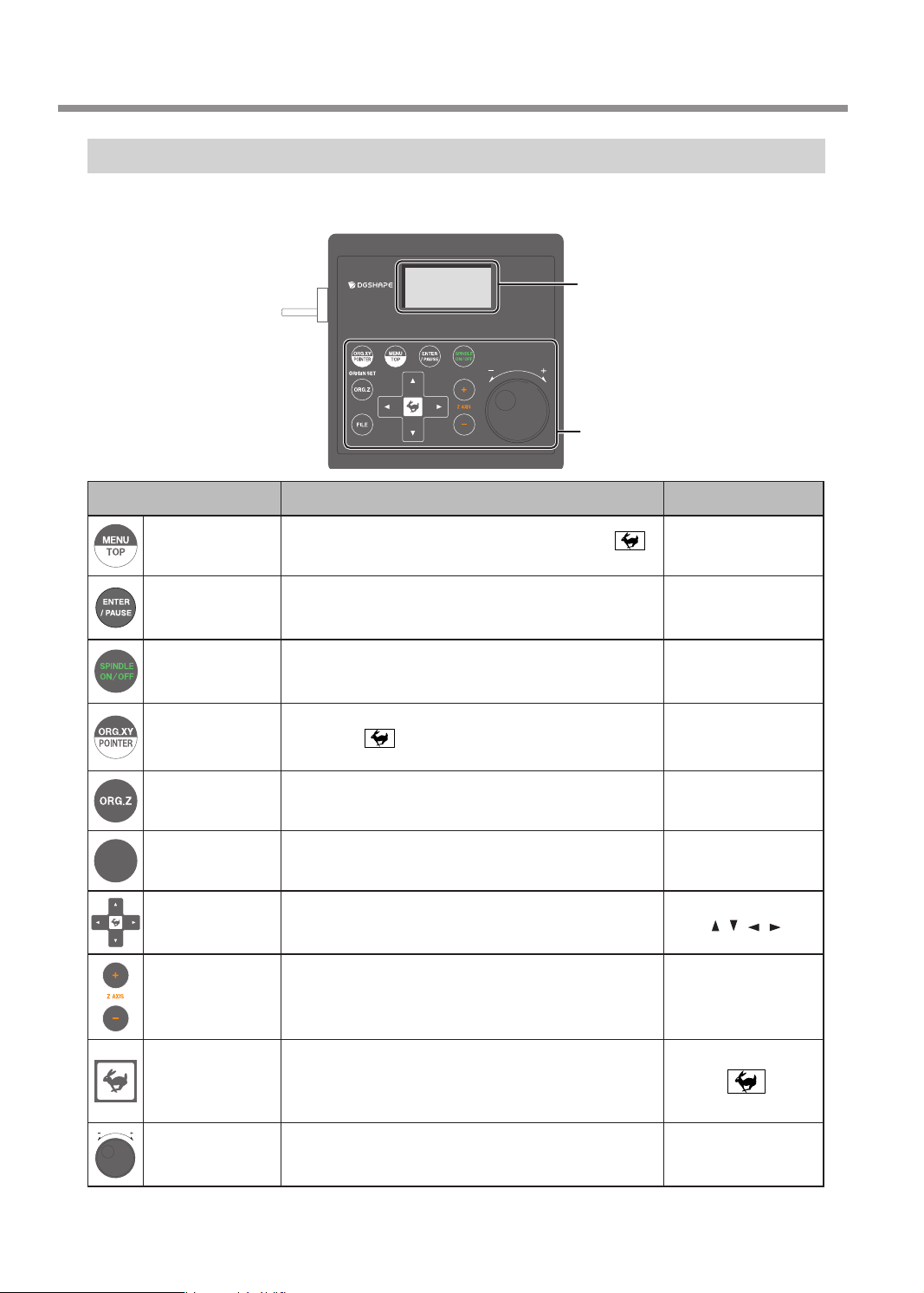
Handy Panel......................................................................................................................................................................8
Viewing the Handy Panel Screen ..............................................................................................................................9
Menu List.......................................................................................................................................................................................... 10
Main Menu ..................................................................................................................................................................... 10
File Menu......................................................................................................................................................................... 11
Origin-setting Menu ................................................................................................................................................... 11
Chapter 2 Basic Operation.............................................................................................12
Emergency Stop to Ensure Safety........................................................................................................................................... 13
How to Perform an Emergency Stop .................................................................................................................... 13
Canceling an Emergency Stop................................................................................................................................ 13
Switching the Power On or O ................................................................................................................................................ 16
Switching the Power On............................................................................................................................................ 16
Switching the Power O............................................................................................................................................ 17
Moving the Tool............................................................................................................................................................................. 18
Terms of Tool Position................................................................................................................................................. 18
Display Example of Tool Position............................................................................................................................ 18
Moving to the Desired Position .............................................................................................................................. 19
Moving to the Specied Position ........................................................................................................................... 20
Pausing and Aborting ................................................................................................................................................................. 21
Pausing and Resuming Engraving......................................................................................................................... 21
Aborting Engraving..................................................................................................................................................... 23
Chapter 3 Basic Engraving Methods ............................................................................24
Checks and Preparation before Engraving.......................................................................................................................... 25
Checking the Flow of Engraving Operation....................................................................................................... 25
Checking Engravable Workpieces.......................................................................................................................... 26
Determining the Item to Create and Required Material and Tool.............................................................. 27
Creating Engraving Data ............................................................................................................................................................ 28
Step 1: Starting Dr. Engrave Plus ............................................................................................................................ 28
Step 2: Creating a Shape ........................................................................................................................................... 30
Step 3: Loading an Image ......................................................................................................................................... 31
Step 4: Entering Text ................................................................................................................................................... 33
Step 5: Setting the Engraving Parameters .......................................................................................................... 35
Step 6: Saving Engraving Data ................................................................................................................................ 37
Starting Engraving........................................................................................................................................................................ 38
Step 1: Setting the Workpiece................................................................................................................................. 38
Step 2: Setting the XY Origin ................................................................................................................................... 39
Step 3: Installing a Character Cutter/Parallel Cutter........................................................................................ 41
Step 4: Checking the Engraving Parameters...................................................................................................... 51
Step 5: Starting Engraving........................................................................................................................................ 54
1

Other Basic Operations............................................................................................................................................................... 56
Adjusting the Tool Feeding Speed and the Number of Rotations during Engraving (Override).... 56
Attaching the Vacuum Adapter .............................................................................................................................. 58
Setting the Lock Lever................................................................................................................................................ 62
Changing the Operation Mode............................................................................................................................... 63
Setting the Avoidance Height of the Tool to Match the Workpiece Shape ............................................ 64
Chapter 4 Maintenance ..................................................................................................66
Maintenance Precautions .......................................................................................................................................................... 67
Daily Care......................................................................................................................................................................................... 68
Cleaning after Engraving Finishes ......................................................................................................................... 68
Cleaning Inside the Spindle Unit Cover............................................................................................................... 69
Storing the Cutter........................................................................................................................................................ 70
Replacing Consumable Parts.................................................................................................................................................... 71
Replacing the Spindle Unit....................................................................................................................................... 71
Replacing the Resin Nose Cone.............................................................................................................................. 73
Correction........................................................................................................................................................................................ 75
Distance Correction..................................................................................................................................................... 75
Laser Correction ........................................................................................................................................................... 75
When Moving the Machine....................................................................................................................................................... 78
When the Machine Has Not Been Used for a Prolonged Period.................................................................................. 80
Spindle Run-in (Warm-up)........................................................................................................................................ 80
Chapter 5 Various Engraving Methods .........................................................................82
Nose Unit Overview and Precautions.................................................................................................................................... 83
The Role of the Nose Unit ......................................................................................................................................... 83
Nose Unit Limitations................................................................................................................................................. 83
When Using Nose Unit............................................................................................................................................... 84
Using Various Tools....................................................................................................................................................................... 85
Determining the Item to Create and Required Material and Tool.............................................................. 85
Considering Engraving Parameters....................................................................................................................... 87
Using a Diamond Scraper ......................................................................................................................................... 88
Using an End Mill ......................................................................................................................................................... 97
Using a Character Cutter/Parallel Cutter (without Nose Unit)...................................................................104
Surface Leveling of the Workpiece Table............................................................................................................................114
Previewing before Engraving .................................................................................................................................................118
Checking the Cutting Path of the Tool (Path Preview)..................................................................................118
Checking the Four Corners of the Engraving Area (Area Preview) ..........................................................119
Checking Any Point on Engraving Data Using a Workpiece (Point Preview) .......................................121
Repeating the Same Engraving .............................................................................................................................................123
Things You Can Do When Creating Engraving Data.......................................................................................................124
Making Use of Layers................................................................................................................................................124
Chapter 6 Appendix ......................................................................................................125
Troubleshooting (Machine Problems).................................................................................................................................126
The Power Does Not Turn On ................................................................................................................................126
Initial Operations Are Not Performed or Fail....................................................................................................126
The Operation Button Does Not Respond When Pushed ...........................................................................126
The USB Cable/LAN Cable Has Come Loose during Engraving.................................................................126
Contents
2

The Machine Does Not Move When Engraving Data Is Sent......................................................................127
The Spindle rotates but Does Not Move From Its Position When Engraving Data Is Sent ..............127
The Spindle Does Not Rotate.................................................................................................................................127
Descent Does Not Stop............................................................................................................................................128
Loud Noise or Unpleasant Noise during Engraving ......................................................................................129
Troubleshooting (Engraving Quality Problems) ..............................................................................................................130
Engraving Is Not Performed on the Expected Position................................................................................130
Cutting-in Depth Is Not Uniform (When Nose Unit Is Used)......................................................................130
Cutting-in Depth Is Not Uniform (When Nose Unit Is Not Used)..............................................................130
The Tool Leaves Tracks at Places Where Cutting-in Starts or Where Lines Change Direction ........131
An Engraved Bottom Surface Is Rough or Burring Remains ......................................................................131
Engraved Lines Are Uneven or Wavy ..................................................................................................................132
Troubleshooting (Installation)................................................................................................................................................133
Driver Installation Is Impossible............................................................................................................................133
Uninstalling the Driver.............................................................................................................................................137
Installing the Driver Separately.............................................................................................................................140
Installing the Software and the Electronic-format Manual Separately..................................................142
Responding to an Error Message ..........................................................................................................................................144
"1000-000*" The % limit switch was not found...............................................................................................145
"1017-0000" The cover was opened during the spindle rotating.............................................................145
"1023-0000" (RML-1) The number of the parameters is incorrect. ...........................................................146
"1024-0000" (RML-1) The parameter is out of range. ....................................................................................146
"1025-0000" (RML-1) A wrong command is detected...................................................................................147
"1029-0000" The spindle experienced an overload.......................................................................................147
"102A-000*" The spindle experienced overcurrent. ......................................................................................148
"102B-0000" The spindle motor temperature is too high. ..........................................................................149
"102D-0000" The spindle cannot be turned.....................................................................................................150
"1044-0000" The automatic Z0 setting failed...................................................................................................150
Locations of the Power Rating and Serial Number Labels ...........................................................................................151
Connector Specications .........................................................................................................................................................152
Expansion Port............................................................................................................................................................152
Machine Specications.............................................................................................................................................................153
External View ...............................................................................................................................................................153
Work Area......................................................................................................................................................................154
Workpiece Table Installation Area Dimensional Drawing...........................................................................155
Laser Pointer Irradiation Area................................................................................................................................155
Main Specications ...................................................................................................................................................156
http://www.dgshape.com/
Copyright © 2018 DGSHAPE Corporation
Company names and product names are trademarks or registered trademarks of their respective holders.
Contents
3

4
Chapter 1 Getting Started
About This Machine............................................................................................................................5
Features of This Machine ......................................................................................................5
Part Names and Functions ...............................................................................................................6
Front and Interior ....................................................................................................................6
Side...............................................................................................................................................7
Handy Panel ..............................................................................................................................8
Viewing the Handy Panel Screen.......................................................................................9
Menu List............................................................................................................................................. 10
Main Menu.............................................................................................................................. 10
File Menu................................................................................................................................. 11
Origin-setting Menu............................................................................................................ 11
Chapter 1 Getting Started

Features of This Machine
This machine is a desktop engraving machine. It can be used in a variety of applications such as making
personalized gifts and accessories by engraving names and creating signboards and industrial products.
• Accommodates various engraving methods
This machine achieves expressive, high-quality engraving of a wide range of types, from contouring and ll,
to hollowing and scribing.
• Outstanding basic performance
The spacious operating area measuring 305 × 230 × 40 mm (W × D × H; 12.0 × 9.1 × 1.6 in.) and the high-
speed spindle that turns at up to 20,000 rpm make for rapid engraving.
• Preview function for preventing failures
You can conrm the engraving area in advance using the laser pointer. By conrming which area of the
workpiece will actually be engraved in advance, you can perform engraving on any location you want.
• Designed for ease of use
You control machine operation using a handy panel that is separate from the machine. This lets you control
the machine from a location aording a clear view of the workpiece and tool. You can also make settings for
the machine simply and easily while viewing the display screen on the handy panel.
• Automatic Z control feature
The machine oers an automatic Z control feature that makes possible engraving at a uniform depth, even
on workpieces with wavy surfaces.
(Trackable undulation height: gentle undulations of about 1 mm (0.04 in.))
• High levels of safety
A front cover and an emergency stop button are standard features of the machine.
About This Machine
5
Chapter 1 Getting Started

Front and Interior
Spindle head*
3
5
4
6 7
2
1
* In this document, the mechanisms around the spindle unit, including the spindle motor, are called the
"spindle head." Also, the rotary-axis area inside the spindle unit is called the "spindle."
No. Part Overview
1Front cover To ensure safety, opening this during engraving or spindle rotation
causes an emergency stop to occur.
2Emergency stop button Press this in an emergency to interrupt this machine's power supply.
"P. 13“Emergency Stop to Ensure Safety”
3Workpiece table The workpiece to be engraved is mounted on this table.
4Handy Panel
This is used to perform tool movement and other machine
operations, and to make various settings.
"P.8 “Handy Panel”
5Laser pointer Laser irradiation is applied from here.
6Spindle unit Install the tool here.
7Lock lever This locks or unlocks the spindle head.
"P. 62“Setting the Lock Lever”
Part Names and Functions
6
Chapter 1 Getting Started

Side
Right Side
1
2
No. Part Overview
1Power switch This switches this machine's power on or off.
"P.16 “Switching the Power On or Off”
2Power cord connector This is for connecting a power cord.
Left Side
3
4
5
No. Part Overview
3LAN connector This is for connecting a LAN cable.
"Setup Guide "Connecting the LAN Cable"
4USB connector This is for connecting a USB cable.
"Setup Guide "Connecting the USB Cable"
5Expansion port This is a connector for external equipment.
"P. 152“Expansion Port”
Part Names and Functions
7
Chapter 1 Getting Started

Handy Panel
This is used to perform tool movement and other machine operations, and to make various settings. Close the
front cover, then perform the operation of the handy panel.
Display screen
Menus, messages, etc. are displayed here.
"P.9 “Viewing the Handy Panel Screen”
Operation button
For details, see table below.
Operation button Functional overview Notation used in this
document
Menu/Top Pressing this changes the menu screen. Hold down
and press this button to return to the main screen.
[MENU/TOP]
Enter/Pause
This executes a selected on-screen item or conrms a
selected item or value. Pressing this during engraving
pauses operation and displays the PAUSE menu.
[ENTER/PAUSE]
Spindle
Holding this down for one second or longer while the
spindle is stopped makes spindle rotation start. Pressing
this during spindle rotation stops rotation.
[SPINDLE]
X/Y-axis Origin
Setting/Laser
Pointer
This sets the reference point for the engraving position.
Hold down and press this button to switch on and
off the irradiation from the laser pointer.
[ORG.XY/POINTER]
Z-axis Origin
Setting This sets the reference point for the engraving position. [ORG.Z]
FILE
File Operates the data in the memory of this machine. [FILE]
Move These move the tool forward and backward, and to the left
and right. [][ ] [ ] [ ]
Z-axis
Movement These move the tool up and down. [+Z]
[-Z]
Feed/Shift
Pressing a Movement or Z-axis Movement button while
holding down this button makes the tool move rapidly. This
is also used as a shift key by pressing it at the same time
as other buttons.
Dial
This adjusts the movement of the tool and the number of
rotations of the spindle. You use this to select items and
change settings on the menu screen.
[Dial]
Part Names and Functions
8
Chapter 1 Getting Started

Viewing the Handy Panel Screen
XYZ 100%
S 100%
X 50.00mm
Y 30.00mm
Z 20.00mm S 5000rpm
012345678901234567 READY 2
5
1
6
4
3
(Main screen)
No. Part Overview
1Laser pointer on/off
When the laser pointer function is turned on, this icon appears. When
the laser pointer function is turned on, the current values of the laser
pointer are displayed on the handy panel.
2Status display Displays the status of the machine such as [READY], [BUSY], and
[PAUSE].
3Current values of the
tool/laser pointer
When the laser pointer function is off, this displays the current values
of the tool seen from the user origin. When the laser pointer function
is on, this displays the current values of the laser pointer seen from
the user origin.
"P. 39“Step 2: Setting the XY Origin”
4Override
Displays the ratio of change (unit: %) relative to the present feeding
speed (XYZ) and the spindle rotating speed (S). The override setting
is only displayed during engraving.
5Spindle load Indicates the increase in load as the gauge increases to the right.
6Number of rotations
of the spindle Displays the number of spindle rotations per minute.
Part Names and Functions
9
Chapter 1 Getting Started

Main Menu
õöëøçúïôíÆóõêë
Æéûú
ÆöøëüïëýÆöçúî
ÆöøëüïëýÆçøëçÆÆÆÆÆÆÆÆÆÆ
ÖרÙÚÛÜÝÞßÖרÙÚÛÜÝÆøëçêÿ
çûúõÆĀÆùëúúïôíÆÆÆÆÆÆÆÆÆÆÆÆÆÆÆÆÆÆÆ
ÆûöÆÆÆÛÔÖÖĒĒ
ÖרÙÚÛÜÝÞßÖרÙÚÛÜÝÆøëçêÿ
SUBNET
255 . 255 . 255 . 000
012345678901234567 READY
GATEWAY
000 . 000 . 000 . 000
012345678901234567 READY
êïùúçôéëÆéõøøëéúïõôÆÆÆÆÆÆÆÆÆÆÆÆÆÆÆÆÆÆÆ
ÆþÆÆ×ÖÖÔÖÖË
ÆÿÆÆ×ÖÖÔÖÖË
ÖרÙÚÛÜÝÞßÖרÙÚÛÜÝÆøëçêÿ
òçùëøÆéõøøëéúïõôÆÆÆÆÆÆÆÆÆÆÆÆÆÆÆÆÆÆ
ÆþÆÆÆÖÖÔÖÖĒĒ
ÆÿÆÆÆÖÖÔÖÖĒĒ
ÖרÙÚÛÜÝÞßÖרÙÚÛÜÝÆøëçêÿ
LAN
IP 192.168.001.254
SUBNET 255.255.255.000
GATEWAY 000.000.000.000
MAC 00:00:00:00:00:00
012345678901234567 READY
ïôìõøóçúïõôÆÆÆÆÆÆÆÆÆÆÆÆÆÆÆÆÆÆÆ
ÆùöïôêòëÆûôïúÆÆÆ×ßßßčÛÖĒ
ÆúõúçòÆýõøñÆÆÆÆÆØØÛÖčØÖĒ
ÖרÙÚÛÜÝÞßÖרÙÚÛÜÝÆøëçêÿ
ïôìõøóçúïõôÆÆÆÆÆÆÆÆÆÆÆÆÆÆÆÆÆÆÆ
ÆùöïôêòëÆûôïúÆÆÆ×ßßßčÛÖĒ
ÆúõúçòÆýõøñÆÆÆÆÆØØÛÖčØÖĒ
ÖרÙÚÛÜÝÞßÖרÙÚÛÜÝÆøëçêÿ
ïôìõøóçúïõôÆÆÆÆÆÆÆÆÆÆÆÆÆÆÆÆÆÆÆ
ÆùöïôêòëÆûôïúÆÆÆ×ßßßčÛÖĒ
ÆúõúçòÆýõøñÆÆÆÆÆØØÛÖčØÖĒ
ÖרÙÚÛÜÝÞßÖרÙÚÛÜÝÆøëçêÿ
ïôìõøóçúïõôÆÆÆÆÆÆÆÆÆÆÆÆÆÆÆÆÆÆÆ
ÆùöïôêòëÆûôïúÆÆÆ×ßßßčÛÖĒ
ÆúõúçòÆýõøñÆÆÆÆÆØØÛÖčØÖĒ
ÖרÙÚÛÜÝÞßÖרÙÚÛÜÝÆøëçêÿ
ïôìõøóçúïõôÆÆÆÆÆÆÆÆÆÆÆÆÆÆÆÆÆÆÆ
ÆùöïôêòëÆûôïúÆÆÆ×ßßßčÛÖĒ
ÆúõúçòÆýõøñÆÆÆÆÆØØÛÖčØÖĒ
ÖרÙÚÛÜÝÞßÖרÙÚÛÜÝÆøëçêÿ
IP
192 . 168 . 001 . 254
012345678901234567 READY
SPINDLE UNIT
ÆýõøñÆúïóëÆÆÆÆÆÆ×ßßßčÛÖĒ
OK Clear
ÖרÙÚÛÜÝÞßÖרÙÚÛÜÝÆREADY
ùëúúïôíùÆÆÆÆÆÆÆÆÆÆÆÆÆ
ÆõöëøçúïôíÆóõêë
ÆùöïôêòëÆøëüõòûúïõôÆÆÆõô
ÆçûúõÆĀÆéõôúøõòÆÆÆÆÆÆõìì
ÆõüëøÆçøëçÆÆÆÆÆÆéõôúïôûë
ÆùúçøúÆóëùùçíëÆÆÆÆÆÆÆÆõô
ÆçûúõÆĀÆùëúúïôí
ÆêïùúçôéëÆéõøøëéúïõô
ÆòçùëøÆéõøøëéúïõô
Æòçô
Æïôìõøóçúïõô
ÖרÙÚÛÜÝÞßÖרÙÚÛÜÝÆøëçêÿ
óõüëÆÆÆÆÆÆÆÆÆÆÆÆÆÆÆÆÆÆÆÆ
ÆüïëýÆöõùïúïõô
Æéëôúëø
ÆûùëøÆõøïíïôÆþÿ
ÆóçéîïôëÆõøïíïôÆþÿ
ÖרÙÚÛÜÝÞßÖרÙÚÛÜÝÆøëçêÿ
[MENU]
"P.20
"P.63
"P.75
"P.75
"P.71
"Setup Guide
"P.64
Main screen
[MENU]
[ENTER]
[ENTER]
[ENTER]
Turn the [Dial] to move the cursor on the screen or change the setting values.
* Press + [MENU] to return to the main screen.
Press [MENU] to return to the
previous screen.(*)
Press [MENU] to return to the
previous screen.(*)
Menu List
10
Chapter 1 Getting Started

File Menu
ìïòëÆõöëøçúïõôÆÆÆÆÆÆÆÆÆÆÆÆÆÆÆÆÆÆÆ
ÆùúçøúÆéûúúïôí
ÆùúçøúÆöøëüïëýÆöçúî
ÆùúçøúÆöøëüïëýÆçøëç
Æêëòëúë
ÖרÙÚÛÜÝÞßÖרÙÚÛÜÝÆøëçêÿ
ìïòëÆÆÆÆÆÆÆÆÆÆÆÆÆÆÆÆÆÆÆ
Æéõöÿ
ÖרÙÚÛÜÝÞßÖרÙÚÛÜÝÆøëçêÿ
Main screen
[FILE]
"P.123
[MENU]
Origin-setting Menu
• Turn the [Dial] to move the cursor on the screen.
• Use [ ], [ ], [ ], [ ], [+Z], and [−Z] to change the settings.
• Press [MENU] to return to the main screen.
ORIGIN SET Z
Z0
Z -30.00mm
012345678901234567 READY
ORIGIN SET XY
ÆþÿƄƄƄƄþƄƄƄƄÿ
ÆÆþƄÙÞÔÞÞĒĒ
ÆÆÿÆÆ×ÝÔÖÖĒĒ
ÖרÙÚÛÜÝÞßÖרÙÚÛÜÝÆREADY
Main screen
[ORG.XY]
[ORG.Z]
"P.39
"P.108
"P.100
Menu List
11
Chapter 1 Getting Started

12
Chapter 2 Basic Operation
Emergency Stop to Ensure Safety .............................................................................................. 13
How to Perform an Emergency Stop............................................................................. 13
Canceling an Emergency Stop.........................................................................................13
Switching the Power On or O.................................................................................................... 16
Switching the Power On .................................................................................................... 16
Switching the Power O .................................................................................................... 17
Moving the Tool ................................................................................................................................ 18
Terms of Tool Position......................................................................................................... 18
Display Example of Tool Position.................................................................................... 18
Moving to the Desired Position....................................................................................... 19
Moving to the Specied Position ................................................................................... 20
Pausing and Aborting..................................................................................................................... 21
Pausing and Resuming Engraving ................................................................................. 21
Aborting Engraving............................................................................................................. 23
Chapter 2 Basic Operation

How to Perform an Emergency Stop
Procedure
Press the emergency stop button.
Operation stops immediately.
Emergency stop button
Canceling an Emergency Stop
Procedure
A Switch off the power switch.
OFF
Emergency Stop to Ensure Safety
13
Chapter 2 Basic Operation

B Turn the button in the direction of the arrows.
The button goes up, and the emergency stop is canceled.
Emergency stop button
C Switch on the power switch.
ON
Emergency Stop to Ensure Safety
14
Chapter 2 Basic Operation

D When the screen shown below appears after approximately three seconds, press [ENTER/
PAUSE].
The spindle head moves to the left of the back of this machine (this movement at the machine's startup
is called the "initial operation").
* "XXX" indicates the version
number of the machine's
rmware.
Hit [ENTER] key.
Vxxx
When the initial operation is complete, the main screen appears.
X 15.00mm
Y 23.00mm
Z 0.00mm S 5000rpm
012345678901234567 READY
Emergency Stop to Ensure Safety
15
Chapter 2 Basic Operation

Switching the Power On
When the machine is connected to a computer, install the driver, and then turn on the power.
"Setup Guide "Installing the Software"
Procedure
A Close the front cover.
B Switch on the power switch.
ON
Switching the Power On or Off
16
Chapter 2 Basic Operation

C When the screen shown below appears after approximately three seconds, press [ENTER/
PAUSE].
The spindle head moves to the left of the back of this machine (this movement at the machine's startup
is called the "initial operation").
* "XXX" indicates the version
number of the machine's
rmware.
Hit [ENTER] key.
Vxxx
When the initial operation is complete, the following screen appears.
X 15.00mm
Y 23.00mm
Z 0.00mm S 5000rpm
012345678901234567 READY
MEMO
The factory default setting for the language used for on-screen display is English. For the method to
change the display language to Japanese, see the Setup Guide.
Switching the Power Off
Procedure
Make sure the machine is not in operation, then turn off the power switch.
The display screen on the handy panel goes dark.
OFF
O
Switching the Power On or Off
17
Chapter 2 Basic Operation

Terms of Tool Position
This manual uses the following terms to indicate the position of the tool.
Terms Overview
Coordinates
These refer to the numerical values that indicate the position of the tool on each of the X/Y/Z axis. They are represented
along with the axis, and the values are represented as positive or negative numbers.
Axis Distance from the origin
XYZ 100%
S 100%
X 35.00mm
Y 23.00mm
Z 0.00mm S 5000rpm
01234567890123456 待機中
(Representation)
The following are the two types of coordinates.
• "Machine coordinates": Coordinates whose origin is a machine-specic origin (machine origin) that
cannot be changed.
• "User coordinates": Coordinates whose origin is an origin that can be changed by the user (user origin).
Origin This refers to the origin ("0" position) of coordinates.
X
Y
Z
Origin
X-axis
coordinate
This refers to the distance from the origin of the X
axis direction (horizontal direction when the table is
seen from directly above).
Y-axis
coordinate
This refers to the distance from the origin of the Y
axis direction (vertical direction when the table is
seen from directly above).
Z-axis
coordinate
This refers to the distance from the origin of the Z
axis direction (height direction).
Display Example of Tool Position
¾When the tool has moved from the origin by 50 mm (2.0 in.) along the X axis, 30 mm (1.2 in.) along the Y
axis, and 20 mm (0.8 in.) along the Z axis.
50 mm (2.0 in.) 30 mm (1.2 in.)
20 mm (0.8 in.)
Origin
Actual tool position
This tool position is displayed on the handy panel's main screen as shown below.
X 50.00mm
Y 30.00mm
Z 20.00mm S 5000rpm
012345678901234567 READY
Moving the Tool
18
Chapter 2 Basic Operation
Other manuals for DE-3
1
Table of contents
Other DGSHAPE Engraver manuals